Table of Contents
Advertisement
Quick Links
Advertisement
Table of Contents

Subscribe to Our Youtube Channel
Related Manuals for VETRON 4000


Summary of Contents for VETRON 4000
- Page 1 4000 » INSTRUCTION MANUAL 05/2022...
- Page 3 4000 » INSTRUCTION BOOK 05/2022 STANDARD: » 4010 » 4020 » 4030...
- Page 4 VETRON | TYPICAL GmbH inadmissible and punishable. VETRON | TYPICAL GmbH is only liable for damage caused by intent or gross negligence on the part of the manufacturer. Otherwise, liability is excluded.
- Page 5 01.04. PRODUCT INTRODUCTION / INTENDED USE / CONFORMITY DECLARATION 01.05. TECHNICAL DATA 01.06. TRANSPORT - PACKAGING - DISPOSAL - STORAGE /FIRST COMMISSIONING / DECOMMISSIONING 01.07. MOUNTING SAFETY DEVICES FOR TILTING 05/2022 VETRON 4000 - FLAT BED MACHINE - INSTRUCTION BOOK...
- Page 6 03.07. TOP FEED STROKE 03.08. BACK TACK 03.09. ENGAGING THE SAFETY CLUTCH 03.10. SAFETY SPRING 04. MAINTENANCE 04.01. CLEANING EXPLANATION 04.02. OIL LEVEL CHECK 04.03. CLEANING THE MACHINE 04.04. PNEUMATIC SYSTEM 05/2022 VETRON 4000 - FLAT BED MACHINE - INSTRUCTION BOOK...
- Page 7 05. WEAR PARTS 05.01. GENERAL INFORMATION 05.02. LISTING 06. ELECTRICAL CONNECTION 06.01. CABLE 06.02. PLUG ASSIGNMENT 06.02.01. BACK OF THE CONTROLLER 06.02.02. PIN DEFINITION 07. SUPPORT FORMULAR 01. COMPLAINT FORM 05/2022 VETRON 4000 - FLAT BED MACHINE - INSTRUCTION BOOK...
-
Page 8: General Safety Instructions
The manufacturer assumes no responsibility for damage caused by changes or modifications. » For repairs, only spare parts approved by VETRON may be used. In case of infringement the guarantee expires. » The machines are to be used only for the purpose intended. - Page 9 » Operating and specialist personnel are obliged to observe the safety instructions given in the instructions for use during all work. 05/2022 VETRON 4000 - FLAT BED MACHINE - INSTRUCTION BOOK...
- Page 10 This symbol indicates that there is an increased risk of burning here. MAGNET! This symbol indicates that there is a magnet field. INFORMATION! This symbol displays information ADVICE! This symbol indicates important information. 05/2022 VETRON 4000 - FLAT BED MACHINE - INSTRUCTION BOOK...
-
Page 11: Danger Notes
Crushing and bruising due to tilting the machine Make sure safety spring is mounted. Risk of injury when machine is tilted back. SAFETY PRECAUTIONS! The finger guard must not be removed! 05/2022 VETRON 4000 - FLAT BED MACHINE - INSTRUCTION BOOK... -
Page 12: Intended Use
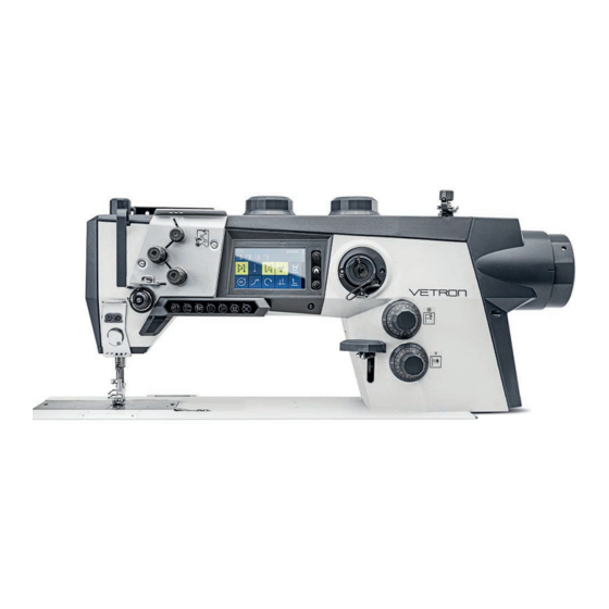
LED sewing light and an integrated modern touch control panel in the machine arm, the VETRON 4000 series o ers all the features of a modern, classic industrial sewing machine. Other features include are a powerful main drive and low-noise, low-vibration operation due to alumi- num arm and head covers. -
Page 13: Technical Data
605 x 210mm Netto weight 55 kg Gross weight 70kg Operating voltage AC 220-240V / 50-60Hz Rated power 1200W Noise indication 80dB(A) Versions and subclasses can be found under: www.VETRONtypical.com 05/2022 VETRON 4000 - FLAT BED MACHINE - INSTRUCTION BOOK... -
Page 14: First Commissioning
02. Pull out the mains plug. 03. Disconnect the machine from the compressed air supply, if available. 04. Clean the machine if necessary. 05. If possible, cover the machine to avoid soiling. 05/2022 VETRON 4000 - FLAT BED MACHINE - INSTRUCTION BOOK... - Page 15 Crushing and bruising due to tilting the machine For di erent adjustments, the safety cylinder should be unhooked. Caution is advised, when returning the sewing machine to its original position. After work, reattach the safety cylinder. 05/2022 VETRON 4000 - FLAT BED MACHINE - INSTRUCTION BOOK...
-
Page 16: Machine Description
Bobbin thread winder (see chapter 03.08.) Thread tension for bobbin thread Top feed stroke knob for higher stroke. Switchable via function bar (see chapter 02.05.) Top feed stroke knob (see chapter 03.06.) 05/2022 VETRON 4000 - FLAT BED MACHINE - INSTRUCTION BOOK... - Page 17 02.02. CONTROL & MAIN SWITCH MACHINE MAIN SWITCH Switches the machine ON / OFF USB-DONGLE Updates and programs can be transferred to/from a USB dongle 05/2022 VETRON 4000 - FLAT BED MACHINE - INSTRUCTION BOOK...
-
Page 18: Knee Switch (Optional)
It is possible to assign various functions to the knee switch such as the 2nd top feed stroke, the 2nd stitch length and the 2nd thread tension. NOTE: See enclosed operating instruction book YSC -90A0 Servo System. 05/2022 VETRON 4000 - FLAT BED MACHINE - INSTRUCTION BOOK... - Page 19 Constant sewing speed (adjustable via parameter M502) Variable sewing speed from 0-100% of the chosen maximum speed (depending on sewing program) Sewing feet lift Seam end procedure activation (depending on sewing program) 05/2022 VETRON 4000 - FLAT BED MACHINE - INSTRUCTION BOOK...
-
Page 20: Function Bar
Switching between lower and higher feed stroke Back tack suppression Change of needle position Switching between small and large stitch length Activation of the 2nd thread tension For 2-needle center seam guide Lock button 05/2022 VETRON 4000 - FLAT BED MACHINE - INSTRUCTION BOOK... -
Page 21: Function Key
Various functions can be assigned to this key. These are set via the parameters and should only be carried out by a service technician. NOTE: See enclosed operating instruction book YSC -90A0 Servo System. 05/2022 VETRON 4000 - FLAT BED MACHINE - INSTRUCTION BOOK... -
Page 22: Touch Display
Selection: O , Single, Double, Multiple Shows current seam Seam display Free sewing, programmed sewing (displays the seam section that is being sewn). End back tack Selection: O , Single, Double, Multiple 05/2022 VETRON 4000 - FLAT BED MACHINE - INSTRUCTION BOOK... - Page 23 Foot position at sewing stop Auto foot lift after sewing stop: Up / Down (refer to 06.06) Foot position after thread cutting Auto foot lift after thread cut: Up / Down (refer to 06.06) 05/2022 VETRON 4000 - FLAT BED MACHINE - INSTRUCTION BOOK...
-
Page 24: Operation Of The Machine
04. Tighten the screw again. 05. Push the lock button (X-button) or switch the machine on again. 05/2022 VETRON 4000 - FLAT BED MACHINE - INSTRUCTION BOOK... - Page 25 04. Tighten the screw again. 05. Push the lock button (X-button) or switch the machine on again. 05/2022 VETRON 4000 - FLAT BED MACHINE - INSTRUCTION BOOK...
- Page 26 » If the thread tension is set too high, the stitch pattern will be poor and the thread will break ADVICE! Push the lock button (X-button) on the function bar to end the „LOCKED MODE“ or switch the machine on again. 05/2022 VETRON 4000 - FLAT BED MACHINE - INSTRUCTION BOOK...
- Page 27 03. The sewing feet can be changed. 04. Tighten the screws again. ADVICE! Push the lock button (X-button) on the function bar to end the „LOCKED MODE“ or switch the machine on again. 05/2022 VETRON 4000 - FLAT BED MACHINE - INSTRUCTION BOOK...
- Page 28 06. The bobbin thread tension can be adjusted at screw ADVICE! Push the lock button (X-button) on the function bar to end the „LOCKED MODE“ or switch the machine on again. 05/2022 VETRON 4000 - FLAT BED MACHINE - INSTRUCTION BOOK...
-
Page 29: Winding The Bobbin Thread
ADVICE! If necessary, the thread guide can be slightly moved to the left or right to optimize the thread flow to the bobbin. To do so, loosen screw 05/2022 VETRON 4000 - FLAT BED MACHINE - INSTRUCTION BOOK... -
Page 30: Stitch Length
The knob will jam if you try to do this. Do not try to overcome the resistance with greater force - this can lead to mechanical damage to the machine. 05/2022 VETRON 4000 - FLAT BED MACHINE - INSTRUCTION BOOK... -
Page 31: Top Feed Stroke
. The knob will jam if you try to do this. Do not try to overcome the resistance with greater force - this can lead to mechanical damage to the machine. 05/2022 VETRON 4000 - FLAT BED MACHINE - INSTRUCTION BOOK... - Page 32 03.08. BACK TACK Reverse sewing can be carried out by manually pressing lever Also alternatively via function key . (Factory default setting) 05/2022 VETRON 4000 - FLAT BED MACHINE - INSTRUCTION BOOK...
- Page 33 06. Check the needle bar rise. (refer to the adjustment manual). If confirmed, the machine is ready for use again. 05/2022 VETRON 4000 - FLAT BED MACHINE - INSTRUCTION BOOK...
- Page 34 03. Under consideration that nothing is between machine and table , the machine can now be tilted forward. 04. The machine is ready for use again. 05/2022 VETRON 4000 - FLAT BED MACHINE - INSTRUCTION BOOK...
-
Page 35: Maintenance
(X-button) on the function bar before maintenance work. The threading symbol is shown in the display. Failure to comply produces a risk of injury in case of an unintentional machine operation. 05/2022 VETRON 4000 - FLAT BED MACHINE - INSTRUCTION BOOK... -
Page 36: Oil Level Check
If you get oil on your skin, make sure you clean it o the skin thoroughly. In case you should swallow the oil seek medical attention immediately. Or call the service hotline: +49 631 / 2014 - 460 05/2022 VETRON 4000 - FLAT BED MACHINE - INSTRUCTION BOOK... -
Page 37: Cleaning The Machine
Push the lock button (X-button) on the function bar to end the „LOCKED MODE“ or switch the machine on again. If you tilt the machine during power on, a gravity sensor automatically switches the machine into „LOCKED MODE”. This is noted on the display. 05/2022 VETRON 4000 - FLAT BED MACHINE - INSTRUCTION BOOK... -
Page 38: Pneumatic System
» Re-assemble the maintenance unit. Check for system leaks. ADVICE! Push the lock button (X-button) on the function bar to end the „LOCKED MODE“ or switch the machine on again. 05/2022 VETRON 4000 - FLAT BED MACHINE - INSTRUCTION BOOK... -
Page 39: Wear Parts
» This Wear Parts List shows the main parts of the machine. A detailed list for the complete machine is available on our website www.vetrontypical.com and can also be ordered as a manual. 05/2022 VETRON 4000 - FLAT BED MACHINE - INSTRUCTION BOOK... - Page 40 (2x) 394WF17-001N DIN 6912 - M4x8 (2x) DIN 912 - M3x8 516WF5-003 179WF5-001 DIN 913 M3x3 (2x) DIN 913 M4x4 516WF5-004 DIN 965 M2,5x3 394WF20-001M Needle- System 134-35 458WF20-001B 05/2022 VETRON 4000 - FLAT BED MACHINE - INSTRUCTION BOOK...
- Page 41 559 3243 10 (32mm) DIN 913 M3x6 (2x) 559 3110 09 (26mm) 559 3111 09 (32mm) DIN 912 M5x8 DIN 7991 M4x10 DIN 988 - 5x10x1 559 0320 10 559 0313 10 516WF14-001 05/2022 VETRON 4000 - FLAT BED MACHINE - INSTRUCTION BOOK...
- Page 42 05. WEAR PARTS 05/2022 VETRON 4000 - FLAT BED MACHINE - INSTRUCTION BOOK...
-
Page 43: Electrical Connection
2 box 3 ATTENTION: The yellow-green earth cable must be connected to the earth properly. Otherwise there are risks of human electric shock and the controller doesn’t work properly sometimes. 05/2022 VETRON 4000 - FLAT BED MACHINE - INSTRUCTION BOOK... -
Page 44: Pin Definition
INTERFACE ICON DEFINITION DEFINITION DC31V Output-04 Output-02 Output-05 Output-01 Output-06 Output-03 Output-07 Output-04 Output-10 Output-05 DC31V Output-06 Output-02 Output-07 Output-01 Output-10 DC31V DC31V Output-09 Output-02 Output-09 X200 Output-01 Output-08 Output-03 Output-08 05/2022 VETRON 4000 - FLAT BED MACHINE - INSTRUCTION BOOK... - Page 45 DEFINITION EXT-SYNC CANL UART-RX CANH X100 UART-TX NORMAL STANDING INTERFACE ICON PEDAL PEDAL PEDAL - AN PEDAL - AN INT 2 SPI-SCK SPI-MISO INT 1 PEDAL INT 3 SPI-NSS SPI-MOSI 05/2022 VETRON 4000 - FLAT BED MACHINE - INSTRUCTION BOOK...
- Page 46 06.02.02. PIN DEFINITION -3-3 INTERFACE ICON DEFINITION CANL HMI-RXD CANH PANEL HMI-TXD INTERFACE ICON DEFINITION MC-U MC-W MC-CHA M1.1 MC-SYNC MC-V MC-CHB INTERFACE ICON DEFINITION EARTH A phase B phase C phase 05/2022 VETRON 4000 - FLAT BED MACHINE - INSTRUCTION BOOK...
-
Page 47: Complaint Form
Please send the defective part(s) and completed document to: Vetron Typical Europe GmbH Clara-Immerwahr-Str. 6 67661 Kaiserslautern / Germany Phone: +49 (0)6301 320 75-0 Fax: +49 (0)6301 320 75-1 Or contact us by mail: support@vetrontypical.com 05/2022 VETRON 4000 - FLAT BED MACHINE - INSTRUCTION BOOK... - Page 48 VETRON TYPICAL EUROPE GmbH Clara-Immerwahr-Str. 6 67661 Kaiserslautern, Germany Tel.: +49 6301 320 75-0 Fax: +49 6301 320 75-11 info@vetrontypical.com www.vetrontypical.com...
- Page 49 YSC-90A0 Servo System INSTRUCTION BOOK 03/2023...
- Page 50 All rights reserved. The instructions for use, service instructions, parts lists are protected by copyright. Any reuse of the content outside the copyright is without the written consent of VETRON | Typical GmbH inadmissible and punishable. VETRON | Typical GmbH is only liable for damage caused by intent or gross negligence on the part of the manufacturer.
- Page 51 INDEX YSC-90A0 AC SERVO SYSTEM 01. SAFETY INSTRUCTIONS 01.01. WORKING ENVIRONMENT / INSTALLATION 02. ELECTRICAL CONNECTION 02.01. CABLE 02.02. WIRING DIAGRAM 02.02.01. CONNECTORS & CONNECTIONS 02.03. YSC-90A0 INPUTS & OUTPUTS DEFAULT CONFIGURATION 02.04. PIN DEFINITION 03. TOUCH PANEL 03.01. WELCOME 03.02.
- Page 52 INDEX YSC-90A0 AC SERVO SYSTEM 06. SETTING THE BASIC FUNCTIONS 06.01. MAXIMUM SPEED 06.02. SETTING BACKTACK AND SEAM 06.02.01. COMMON SETTING ABOUT START/END TACKING 06.02.02. STITCH IN STITCH 06.02.03. FREE SEWING PROGRAM 06.02.04. BAR SEAM PROGRAM 06.02.05. FIXED STITCHES PROGRAM 06.03.
-
Page 53: Working Environment
01. SAFETY INSTRUCTIONS 01.01. WORKING ENVIRONMENT / INSTALLATION To ensure correct operation and safety, read these operating instructions before using your new machine. The controller YSC-90A0 is used for an industrial sewing machine. With industrial sewing machines, it is normal to work directly in front of moving parts such as the needle and thread take-up. - Page 54 02. ELECTRICAL CONNECTION 02.01. CABLE Work on the electrical equipment may only be performed by qualified technicians or personal who have undergone the necessary training. The power supply is AC 220V! Single phase: 220V power connection Light (brown) AC ~ 220V Neutral (blue) Earth (yellow-green) Earth...
- Page 55 02.02. WIRING DIAGRAM 02.02.01. CONNECTORS & CONNECTIONS -1-4 » M1 - Sewing motor » M1.1 - Sewing motor encoder interface » PANEL - Touch panel » PEDAL - Pedal » X100 - CAN Bus » X101 - TTL I/O » X200 - Outputs 03/2023 YSC-90A0 INSTRUCTION BOOK...
- Page 56 02.02.01. CONNECTORS & CONNECTIONS -2-4 CONNECTION CIRCUIT BOARD CONNECTOR DESCRIPTION DESCRIPTION Output-02 Output-02 Output-01 Output-02 Output-01 Output-01 Output-03 Output-03 To control box connector X200 Output-04 Output-04 (Solenoid outputs) Output-05 Output-05 Output-06 Output-06 Output-07 Output-07 Output-10 Output-10 Output-09 Output-09 Output-08 Output-08 Reverse SW.
- Page 57 02.02.01. CONNECTORS & CONNECTIONS -3-4 CONNECTION CIRCUIT BOARD CONNECTOR DESCRIPTION Electron. Handwheel CHA Reserved for Electron. Handwheel CHB electronic handwheel Input-04 For stroke knob potentiometer Input-07 input Input-05 Reserved for knee switch input Reserved for hook cover open Input-01 protection proximity sensor DC12V Input-03 For lighting and machine tilt...
- Page 58 02.02.01. CONNECTORS & CONNECTIONS -4-4 CONNECTION CIRCUIT BOARD CONNECTOR DESCRIPTION DESCRIPTION Output-02 Output-01 Solenoids should be connec- ted to J6 Output-03 Output-08 Output-09 Output-10 Output-07 Air actuator relays should be connected to J3 Output-06 Output-05 Output-04 02.03. YSC-90A0 INPUTS & OUTPUTS DEFAULT CONFIGURATION DESCRIPTION PARAMETER TYPE...
-
Page 59: Pin Definition
DESCRIPTION PARAMETER TYPE DEFAULT FUNCTION Output-01 Fast decay Reserved Output-02 Reserved Output-03 Trimmer Output-04 Additional tension Output-05 Main tension Output-06 Foot lift Output-07 Reverse sewing direction Output-08 Reserved Output-09 Second stitch length Output-10 Stroke height 02.04. PIN DEFINITION -1-3 INTERFACE ICON DEFINITION EARTH A phase... - Page 60 02.04. PIN DEFINITION -2-3 INTERFACE ICON DEFINITION CANL HMI-RXD CANH PANEL HMI-TXD NORMAL STANDING INTERFACE ICON PEDAL PEDAL PEDAL-AN PEDAL-AN INT 2 SPI-SCK SPI-MISO INT 1 PEDAL INT 3 SPI-NSS SPI-MOSI INTERFACE ICON DEFINITION EXT-SYNC CANL UART-RX CANH X100 UART-TX 03/2023 YSC-90A0 INSTRUCTION BOOK...
- Page 61 02.04. PIN DEFINITION -3-3 INTERFACE ICON DEFINITION DEFINITION CHA2 Function bar-LOCK Machine ID-SDA Machine ID-SCL Input-06 (digital) Function bar-CLK Input-05 (digital) CHB 2 Input-02 (digital) Input-04 (digital) DC12V Input-03 (digital) DC12V Elec Hand Wheel-CHB Input-10 (analog) Elec Hand Wheel-CHA Input-09 (analog) Input-08 (analog) Input-07 (analog) X101...
-
Page 62: Touch Panel
03. TOUCH PANEL 03.01. WELCOME The panel is connected to control box via a cable. If the connection is normal, the main sewing interface will be displayed after welcome: 03.02. MAIN SEWING INTERFACE -1-2 DISCRIPTION Lock key (Physical button) Lock / unlock touch display Configuration (Physical button) Enter config interface Return (Physical button) - Page 63 03.02. MAIN SEWING INTERFACE -2-2 DISCRIPTION Locked status The icon shows the status of the touch display Increase / decrease the edibale value. It will be hiodden when there is Values no edit Program setting Program setting key. Enter program setting interface, (refer to 06.02) Increase or decrease the number of stitches in segments A, B, C, D Stiches setting with + / -...
-
Page 64: Preparation And Test
04. PREPARATION AND TEST 04.01. HOW TO ENTER THE INTERFACE Press Config button when switching on the controller to enter Preparation and Test interface. You can select: language, the machine model, make a factory reset, set pedal type, set the machine ZERO position, test the input and output, etc. -
Page 65: Factory Reset
04.03. FACTORY RESET At Preparation and Test interface, press icon „Factory Reset“. Select: 1- „Parameter“, 2-„Machine ZERO“, 3-„Error record“, 4-„Statistics“ or all items to reset. The machine needs to be restarted. 04.04. MACHINE ZERO POSITION At Preparation and Test interface, press icon „Phase base by needle bar“ or „Phase base by lever “. The first option sets the base at highest position of the needle bar. -
Page 66: Output Tests
04.06. SELECT PEDAL TYPE At Preparation and Test interface, press icon „Pedal“. You can choose the normal pedal or standing operate pedal, click OK to save. 04.07. INPUT TESTS At Preparation and Test interface, press icon „Measure“. You can check the values of the various functions. 04.08. -
Page 67: Safety Switch
04.09. SAFETY SWITCH At Preparation and Test interface, press icon „Safety switch“. Various safety divices can be switched on or o : machine-tilt-protection, hook covering protection and eye protection. 04.10. LANGUAGE At Preparation and Test interface, press icon „Language“. Choose the language which you need. Click OK to save. The machine needs to be restarted. 03/2023 YSC-90A0 INSTRUCTION BOOK... -
Page 68: System Operation
05. SYSTEM OPERATION 05.01. PARAMETER AUTHORITY 05.01.01. AUTHORITY STRUCTURE LEVEL ACCESSIBLE PARAMETER ICON Operator Basic parameters Technician Advanced Parameters Developer Parameters about motor drive 05.01.02. ACCESS RIGHTS TO THE TECHNICIANS LEVEL NOTE! Normally, only the operator has basic authority. The symbol is gray. The technicians level is not to be accessed by normal users. -
Page 69: Change Password
05.03. USER SETTINGS 05.03.01. SELECT THE FUNCTION CATEGORY TO BE ADJUSTED At Main sewing interface, press „User setting button“ to enter „User setting interface“. Most items are the parameter setting by categorized function. 05.03.02. ADJUST PARAMETER VALUE Click a function category icon to enter the interface. The parameter list is on the left side, where you can swipe the list and select a parameter to adjust. -
Page 70: View Software Version
05.04. VIEW SOFTWARE VERSION At Main sewing interface, press Configuration key (Physical button) . Enter „User setting interface“, then select sub-item: „About“. 05.05. MONITOR At Main sewing interface, press Configuration key Enter „User setting interface“, then select sub-item: „Monitor“. You can select the monitor value by the arrow button. The monitor items are: instant speed, instant angle, raw encoder value, hall sensor of motor, electric angle, stroke knob sensor, etc. -
Page 71: Setting The Basic Functions
06. SETTING THE BASIC FUNCTIONS 06.01. MAXIMUM SPEED INDEX UNIT DESCRIPTION 3500 Maximum speed 2000 Speed of mulitple tacking 2000 Speed of programmed stitches Di erent machine classes have di erent maximum speeds. Setting speed: press the „Speed“ icon at Main sewing interface. The speed value and „+ / -“ button will be dis- played. - Page 72 06.02.01. COMMON SETTING ABOUT START/END TACKING INDEX UNIT DESCRIPTION 2000 Speed in backtack at seam begin 2000 Speed in backtack at seam end Reverse solenoid action time (Start) Reverse solenoid release time (End) degree Reverse power on angle degree Reverse power o angle Ornamental-stitch backtack at seam start 0 = OFF 1 = ON, the motor will stop at sewing direction changing point...
- Page 73 06.02.03. FREE SEWING PROGRAM Click Seam setting button at Main sewing interface, select P001 program. This seam will be run without stitch counting. Set the start tacking: Click the tacking stitches number to adjust the value. Click the start tacking button to change the tacking mode.
- Page 74 06.02.04. BAR SEAM PROGRAM Click Seam setting button at Main sewing interface, select P002 program (multible tacking). There are 5 editable numbers. The 4 numbers at 1st line is ABCD, the last number at 2nd line is E. The segments are programmed as E, range 1~15. The stitches of first segment is defined as A, the stitches of second segment is defined as B, the stitches of other segments are defined as C (forward) and D (backward).
- Page 75 06.02.05. FIXED STITCHES PROGRAM This seam can be programmed with a maximum 25 segments and a maximum of 99 stitches for each segment. » Click „Seam setting“ button at Main sewing interface, select P003~P009 program. » Click the edit button to enter the fixed-stitches seam edit interface. »...
-
Page 76: Soft Start
06.03. SOFT START INDEX UNIT DESCRIPTION Soft start 0 = OFF 1 = ON Speed of soft start stitches Number of soft start stitches Click „soft start“ button . Is the icon on, the soft start is ON. Is the icon o , the soft start is OFF Functions: when beginning a new seam, speed is determined by the pedal and limited to the soft start speed. -
Page 77: Sewing Foot Lift
06.06. SEWING FOOT LIFT INDEX UNIT DESCRIPTION Sewing foot lift: 0 = OFF 1 = ON Lifting foot confirm delay time: to avoid unexpected foot lifting when stepping backward for trimming, the time is less and the sensitivity is higher Release lift foot delay time Full activation duration of foot lift solenoid Pedal delay time adjustment for debounce... -
Page 78: Thread Tension
06.07. THREAD TRIM -2-2 INDEX UNIT DESCRIPTION degree Reverse of short thread trimming power on angle degree Reverse of short thread trimming power o angle degree Zero stitch length of short thread trimming power on angle degree Zero stitch length of short thread trimming power o angle Thread trim ON: click trim button at Main sewing interface, the icon light is on. -
Page 79: Thread Clamp
06.09. THREAD CLAMP INDEX UNIT DESCRIPTION Thread clamp: 0 = OFF 1 = ON Thread clamp option: 0 = Thread clamp only at start of seam 1 = Thread clamp at start of seam and at turning back 2 = Thread clamp at start of seam and with foot lifting 3 = Thread clamp at start seam, at turning back and with foot lifting 2000 Thread clamp power on time with foot lifting or at turning back... -
Page 80: Seam Center Guide
06.10. FOOT STROKE -2-2 INDEX UNIT DESCRIPTION Full activation duration Duty cycle in time period which PWM activation Adjust parameter of the speed limitation in relation to the sewing foot stroke: if parameter A35 set to 1, the speed is reduced down to parameter S15 when 2nd stroke activated. -
Page 81: Needle Cooling
06.13. NEEDLE COOLING INDEX UNIT DESCRIPTION Needle cooling function: 0 = OFF 1 = ON Full activation duration Duty cycle in time period which PWM action Function: set A48 as to 1, when the motor runs, the cooling air pipe is open. 06.14. -
Page 82: Service Counter
06.15. BOBBIN THREAD MONITOR -2-2 NOTE! Warning process: when the counter is activated, every time 10 stitches are sewn, the value of parameter O44 increases by 1, remaining thread amount decreases by 1. Sewing stops and a notice is shown on the display when the remaining thread amount reach 0, press Return key to reset the counter. - Page 83 06.17. DAILY PIECE COUNTER INDEX UNIT DESCRIPTION Daily piece counter: 0 = OFF 1 = Activated stitches Min number of stitches for counter plus 1 Min number of thread trimming times for counter plus 1 Value of daily piece counter 06.18.
- Page 84 06.18. ASSIGNING INPUT -2-2 INDEX UNIT DESCRIPTION Function of input-07, refer to A04 Function of input-08, refer to A04 Function of input-09, refer to A04 Function of input-10, refer to A04 Input ports include reverse sewing button and buttons on the function bar. Di erent function can be applied directly to these inputs.
- Page 86 VETRON TYPICAL EUROPE GmbH Clara-Immerwahr-Str. 6 67661 Kaiserslautern, Germany Tel.: +49 6301 320 75-0 Fax: +49 6301 320 75-11 info@vetrontypical.com www.vetrontypical.com...
- Page 87 VETRON TYPICAL EUROPE GmbH Clara-Immerwahr-Str. 6 67661 Kaiserslautern, Germany Tel.: +49 6301 320 75-0 Fax: +49 6301 320 75-11 E-mail: info@vetrontypical.com www.vetrontypical.com...
Need help?
Do you have a question about the 4000 and is the answer not in the manual?
Questions and answers