Table of Contents
Advertisement
Quick Links
PCE Americas Inc.
PCE Instruments UK Ltd.
711 Commerce Way
Units 12/13
Suite 8
Southpoint Business Park
Jupiter
Ensign way
FL-33458
Hampshire / Southampton
USA
United Kingdom, SO31 4RF
From outside US: +1
From outside UK: +44
Tel: (561) 320-9162
Tel: (0) 2380 98703 0
Fax: (561) 320-9176
Fax: (0) 2380 98703 9
info@pce-americas.com
info@industrial-needs.com
www.pce-instruments.com/english
www.pce-instruments.com
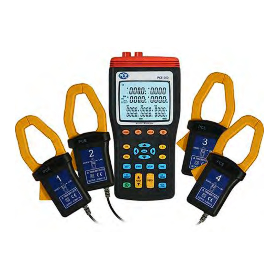
POWER ANALYZER PCE-360
INSTRUCTION MANUAL
Advertisement
Table of Contents

Related Manuals for PCE Instruments PCE-360-ICA


Summary of Contents for PCE Instruments PCE-360-ICA
- Page 1 PCE Americas Inc. PCE Instruments UK Ltd. 711 Commerce Way Units 12/13 Suite 8 Southpoint Business Park Jupiter Ensign way FL-33458 Hampshire / Southampton United Kingdom, SO31 4RF From outside US: +1 From outside UK: +44 Tel: (561) 320-9162 Tel: (0) 2380 98703 0...
-
Page 2: Table Of Contents
User Manual CONTENTS 1. SAFETY INFORMATION ................3 2. INTRODUCTION FEATURE ................7 3. SPECIFICATIONS ..................9 3-1 E : ................ 9 NVIRONMENT ONDITIONS 3-2 S ................9 AFETY PECIFICATIONS 3-3 G ................9 ENERAL PECIFICATION 3-4 E ............... 12 LECTRICAL PECIFICATION 4. - Page 3 User Manual 5-12 E ............54 NABLE OWER UNCTION 6. MAINTENANCE ................... 55 6-1 G ................55 ENERAL AINTENANCE 6-2 B ................55 ATTERY EPLACEMENT 7. SOFTWARE INSTALLATION AND OPERATION ........56 WARRANTY ..................... 74 DISPOSAL ......................74...
-
Page 4: Safety Information
User Manual 1. SAFETY INFORMATION This Instruction Manual provides information and warnings essential for operating this meter in a safe manner and for maintaining it in safe operating condition. Before using this meter, be sure to carefully read the following safety information. - Page 5 User Manual SAFETY SYMBOLS • Caution refer to this manual before using the meter. • This symbol is affixed to the meter where the operator should consult corresponding topics before using relevant functions of the meter. • This mark indicates explanation, which is particularly important that the user should read before using the meter.
- Page 6 User Manual In order to ensure safe operation and to obtain maximum performance from the meter, observe the caution listed below ❑ Installation CAUTION • The meter is designed for indoor use and can be safely used at temperatures ranging from 0°C to 40°C. •...
- Page 7 User Manual WARNING • To prevent electric shock, turn the power off before connecting the test leads and then take measurements. • In order to prevent electrical shock and short – circuit accidents, shut off the power to the line to be measured before connecting the line to be measured to the voltage input terminals.
-
Page 8: Introduction Feature
User Manual WARNING To avoid electrical shock and / or meter damage, use caution when connecting test leads to live components. The jaws of alligator clips can create a short circuit between closely spaced live parts. Avoid making connections to feeder conductors or bus bars at elevated potentials. Whenever, please make connections to the output side of a circuit breaker as possible as you can, which can provide better short circuit protection. - Page 9 User Manual The symptoms of poor power quality include intermittent lock-ups and resets, corrupted data, premature equipment failure, over-heating of components for no apparent cause, etc. The ultimate cost is in downtime, decreased productivity and frustrated personnel. Use power analyzer to power quality trouble shooting can help you keep your power system up and running, troubleshoot problems quickly, improve power efficient, manage energy costs, zero in on harmonics, optimize power system performance, improve power quality and analyze system data to design optimal...
-
Page 10: Specifications
User Manual 3. SPECIFICATIONS 3-1 Environment Conditions: Altitude up to 2000 meters Indoor use only Relatively humidity 80% max. Operation ambient 0 ~ 40°C 3-2 Safety Specifications Category Rating: 1000V Measurement Category III, Pollution Degree 2. : IEC 61010-1 2nd Edition CAT III: Measurement category in which measurements performed in the building installation. - Page 11 User Manual • Maximum voltage between voltage input terminals and earth ground: 1000 Vrms • Maximum rated working voltage for current input: 0.35 Vrms • Maximum current for current probe: 1000 Arms • Numerical 10 display: 10 display 4 digit LCD maximum reading 9999. •...
- Page 12 User Manual 1 x PCE-360 Clamp Meter 4 x Current clamps 4 x Measuring leads 4 x Alligator clips 8 x 1.5 V AA batteries 1 x Power adapter 1 x USB cable 1 x PC software CD-ROM 1 x User manual 1 x Carrying case...
-
Page 13: Electrical Specification
User Manual 3-4 Electrical Specification Accuracy: ±(% of reading + number of digits) at 18°C to 28°C ( 64°C to 82°C) with relative humidity to 80%. The current error is specified within the largest circle which can be drawn inside the jaw. ❑... - Page 14 User Manual ❑ Apparent Power measurement S (KVA): Range Resolution Accuracy 1.0%rdg20dgts 999.9KVA 0.1KVA • Measurement method: Calculate from RMS voltage U and RMS current I. • Display item: Apparent power of each channel and its sum of multiple channels. •...
- Page 15 User Manual ❑ Power Factor measurement (COSψ): Range Resolution Calculated Accuracy 10dgt -1 ~ +1 0.001 • Measurement method: Calculate from apparent power S and active power P S / PF = COSψ= • Display item: Power factor of each channel and its sum of multiple channels. ❑...
- Page 16 User Manual ❑ Three Phase Sequence Detection: Input voltage Normal phase Reverse phase Measurement range indication indication source 3P > 10V U1, U2 and U3 ❑ Active Power Energy measurement (KWh): Active power Range Resolution Timer interval Timer Accuracy accuracy 9.999KWh 0.001KWh 99.99KWh...
- Page 17 User Manual ❑ Reactive Power Energy measurement (Kvarh): Reactive power Range Resolution Timer interval Timer Accuracy accuracy 9.999Kvarh 0.001Kvarh 99.99Kvarh 0.01Kvarh ±50ppm (25°C, 1.0%rdg20dgt 999.9Kvarh 0.1Kvarh 1 sec 77°F) 9.999Mvarh 0.001Mvarh 30.59Mvarh 0.01Mvarh • Measurement display: Display all reactive power consumption (sum of absolute values).
-
Page 18: Parts & Controls
User Manual 4. PARTS & CONTROLS 4-1 Description of Parts & Control keys ¢ » U12 Y-M U23 D-h U31 m-s MAG. - Page 19 User Manual 1. Input for voltage terminals (U1, U2, U3, N). 2. Input for current probe jacks (I1, I2, I3, I4). 3. Plug for external AC adaptor power supply input. 4. Optical interface output. 5. LCD display. 6. WIRING key: Select the type of electrical system under test, press “WIRING” key to select 1P2W (To measure single-phase two-wire power lines), 1P3W (To measure single-phase three-wire power lines), 3P3W2M (To measure three-phase three-wire power...
- Page 20 User Manual key: Backlight function key, press key to turn on and off of backlight. The backlight will switch off automatically after 30 seconds. 10. MAX key: Active power (P), reactive power (Q), and apparent power (S) Maximum / Minimum recording measurement. ...
- Page 21 User Manual Press key to cycle through the Minimum reading for Active power (“P” mark is blinking) with its Q, S, V, A reading and its PF, Θ, Hz, I4 reading by press “PFΘ” and “Hz I4” keys. Minimum reading for Reactive power (“Q” mark is blinking) with its P, S, V, A reading and its PF, Θ, Hz, I4 reading by press “PFΘ”...
- Page 22 User Manual 13. Hz I4 key: Display measured frequency or I4 current probe value control key, the “Hz” or “I4” annunciator is displayed. 14. SET key: Setting current date and time function key, press “SET” key to enter current time setting mode and interval time setting mode for auto datalogging use.
- Page 23 User Manual 20. READ key: Read manual memory data control key. 21. POWER key: Display measured power value control key, the “Pt123”, “Qt123” and “St123” annunciators will be displayed in cycles. 22. ENERGY key: Display total integrated power energy value control key, the three “h”...
-
Page 24: Description Of Display
User Manual 4-2 Description of Display 4.13 4.14 4.15 4.16 4.12 4.11 4.17 4.18 4.19 4.22 4.20 4.10 4.21 4.23 4.25 4.26 4.28 4.30 4.31 4.24 4.27 4.29 4.46 U12 Y-M U23 D-h U3 m-s 4.45 4.32 4.44 4.43 4.33 4.33 4.42 4.38... - Page 25 User Manual HOLD : Display hold mode. REC MAX : Maximum recorded reading. REC MIN : Minimum recorded reading. REC : Recording mode indication and current reading. KW: Active Power Unit: or KWh, MWh, active energy unit. Kvar: Reactive Power Unit or Kvarh, Mvarh reactive energy unit. Display of reactive Power.
- Page 26 User Manual 1P3W: Measure single-phase three-wire power line indicator. 3P3W2M: Measure three-phase three-wire power line indicator. 3P3W3M: Measure three-phase three-wire power line using 3 power meter indication. 3P4W: Measure three-phase four-wire power line indicator. 4.12 PF : Harmonic power factor measured display. PF1: Phase 1 power factor measured display.
- Page 27 User Manual apparent energy measured display indicator. U1: Indicates the display of voltage on phase 1(U1), THDR %, THDF 4.23 % or Harmonic. 4.24 Y-M: Year and Month display indicator Display of Voltage, Date (Year: Month), THDR % or Harmonic order 4.25 number (Hd: 01 ~ Hd: 63) U2: Indicates the display of voltage on phase 2(U2), THDR %, THDF...
- Page 28 User Manual THDF: Voltage or current Total Harmonic Distortion of a waveform to 4.42 its Fundamental indication. 4.43 INTV: Indicates the Auto data logging interval time setting 4.44 STAR: Indicates the start time for energy calculation THDR: Voltage or current Total Harmonic Distortion of a waveform to 4.45 the waveform RMS value indication.
-
Page 29: Operating Instruction
User Manual 5. OPERATING INSTRUCTION CAUTION • If possible, before connecting the meter to the electrical equipment to be tested, take off the electrical equipment’s power. DANGER • Voltage input connectors U1 to U3 are common for input connector N, each input connectors are not insulated. -
Page 30: Ac Current Adaptor
User Manual 5-1 AC Current Adaptor Safety Information Read First: Safety Information To ensure safe operation and service of the current clamp, follow these instructions: • Read the operating instructions before use and follow all safety instructions. • Use the Current Clamp only as specified in the operating instructions, otherwise the clamp’s safety features may not protect you. - Page 31 User Manual Measurement Considerations • Center the conductor inside the Current Clamp jaw. • Make sure the clamp is perpendicular to the conductor. • For optimal reading, make sure the conductor is positioned between the alignment marks on the jaws of the Current Clamp. Observe the following guidelines when making measurements : •...
-
Page 32: Single-Phase 2-Wire (1P2W) Power System Measurement
User Manual 5-2 Single-Phase 2-Wire (1P2W) Power System Measurement Application : Receptacle branch circuit Lighting loads ⚫ Troubleshooting electrical distribution ⚫ Measuring current harmonic. system. ⚫ Measuring power on single phase ⚫ Measuring line rms voltage. loads. ⚫ Measuring line rms current. ⚫... - Page 33 User Manual A: Line, N: Neutral, G: Ground, ➔ Face the arrow toward the load. Ⅲ 1P2W Wiring Connection Diagram 1. Press key to turn on the meter. 2. Press “WIRING” key to select the 1P2W electrical system under test, the “1P2W”...
- Page 34 User Manual CAUTION • If possible, before connecting the voltage test leads and current probe to the electrical equipment to be tested, take off the electrical equipment’s power. Connect the black voltage test alligator to the Neutral Line “N”. ...
- Page 35 User Manual 9. Energy measurement: Press “ENERGY” key, the “Pt”, “Qt”, “St” and “PFt” or “ψt” annunciator and energy integrate start time are displayed. The energy integrate value and the current time will be continuous accumulate. a). KW displays KWh b).
-
Page 36: Single-Phase 3-Wire (1P3W) Power System Measurement
User Manual 5-3 Single-Phase 3-Wire (1P3W) Power System Measurement Application: Same as 1P2W power system measurement. A, B: Line, N: Neutral, G: Ground, ➔ Face the arrow toward the load. ¢ » 1P3W Wiring Connection Diagram 1. Press key to turn on the meter. 2. - Page 37 User Manual 3. Connect the voltage test leads and current probe to the meter. Connect the black voltage test lead to the “N” terminal. Connect the red voltage test lead to the “U1” terminal. Connect the yellow voltage test lead to the “U2” terminal. ...
- Page 38 User Manual If you want to measure ground leakage current, press I4 current probe trigger to open the jaw and fully enclose the ground line “G”. 5. Press “POWER” key to select (P1, Q1, S1, PF1), (P2, Q2, S2, PF2) and (Pt, Qt, St, PFt) measured values.
- Page 39 User Manual Press key to exit the energy measurement. ※ U1 must be connected to voltage source during the measurement of U2, U3, I1, I2 and I3, because U1 is the main signal source of the whole meter measuring system. Otherwise you could not have any measurement from U2, U3, I1, I2 and I3.
-
Page 40: Three-Phase 3-Wire (3P3W2M) Power System Measurement
User Manual 5-4 Three-Phase 3-Wire (3P3W2M) Power System Measurement Using 2 power meter method Application : Induction motors without adjustable speed Induction motors with adjustable speed drive. drive. ⚫ Checking voltage unbalance. ⚫ Checking current on phases. ⚫ Checking current and current unbalance. ⚫... - Page 41 User Manual A, B, C: Line, ➔ Face the arrow toward the load. Ⅲ 3P3W2M Wiring Connection Diagram 1. Press key to turn on the meter. 2. Press “WIRING” key to select the 3P3W2M electrical system under test, the “3P3W2M” annunciator will be displayed. 3.
- Page 42 User Manual equipment to be tested. CAUTION • If possible, before connecting the voltage test leads and current probe to the electrical equipment to be tested, take off the electrical equipment’s power. Connect the black voltage test alligator to the line “B”. ...
- Page 43 User Manual Please refer to section 4-1-10 “MAX” key description. 10. Energy measurement: Press “ENERGY” key, the “Pt”, “Qt”, “St” and “PFt” or “ψt” annunciator and energy integrate start time are displayed. The energy integrate value and the current time will be continuous accumulate. a).
-
Page 44: Three-Phase 3-Wire (3P3W3M) Power System Measurement
User Manual 5-5 Three-Phase 3-Wire (3P3W3M) Power System Measurement Application : Same as 3P3W power system measurement. A, B, C: Line, ➔ Face the arrow toward the load. ¢ » 3P3W3M Wiring Connection Diagram 1. Press key to turn on the meter. 2. - Page 45 User Manual Connect the red voltage test lead to the “U1” terminal. Connect the yellow voltage test lead to the “U2” terminal. Connect the blue voltage test lead to the “U3” terminal. Connect the I1 current probe output plug to the “I1” jack. ...
- Page 46 User Manual MAG.” key description. Please refer to section 4-1-25 “ 9. Power Maximum/Minimum measurement: Please refer to section 4-1-10 “MAX” key description. 10. Energy measurement: Press “ENERGY” key, the “Pt”, “Qt”, “St” and “PFt” or “ψt” annunciator and energy integrate start time are displayed. The energy integrate value and the current time will be continuous accumulate.
-
Page 47: Three-Phase 4-Wire (3P4W) Power System Measurement
User Manual 5-6 Three-Phase 4-Wire (3P4W) Power System Measurement Application: Same as 3P3W power system measurement. A, B, C: Line, N: Neutral, G: Ground, ➔ Face the arrow toward the load. ¢ » 3P4W Wiring Connection Diagram 1. Press key to turn on the meter. 2. - Page 48 User Manual Connect the black voltage test lead to the “N” terminal. Connect the red voltage test lead to the “U1” terminal. Connect the yellow voltage test lead to the “U2” terminal. Connect the blue voltage test lead to the “U3” terminal. ...
- Page 49 User Manual Press “Hz I4” key to cycle shows the Hz and I4 measured values. 7. Voltage and Current THDR THDF measurement: Please refer to section 4-1-12 “THD” key description. 8. Voltage and Current waveform harmonic measurement: MAG.” key description. Please refer to section 4-1-25 “...
-
Page 50: Only One Current I4 Measurement
User Manual 5-7 Only One Current I4 Measurement Application: Measurement any wire current independent of voltage, the same as clamp meter application. ¢ » 1. Press key to turn on the meter. 2. Press “I4” key. 3. Connect the I4 current probe output plug to the “I4” jack. 4. -
Page 51: Manual Data Memory And Read Function Operation
User Manual 5-8 Manual Data Memory and Read Function Operation 1. Clear Manual memory data: Press key to turn off the meter. Press and hold down the “MEMORY” key then press key again to turn on the meter and to enter clear manual memory data mode, the “DATA M CLr 1 YES no”... -
Page 52: Auto Datalogging Function Operation
User Manual 5-9 Auto Datalogging Function Operation 1. Clear SD Card memory data: Press key to turn off the meter. Press and hold down the “MEMORY” key then press key again to turn on the meter and to enter clear manual memory data mode, the “DATA M CLr 1 YES no”... - Page 53 User Manual Enter Auto datalogging mode. Press “START” key to start Auto data logging, the “DATA M” will be displayed, the “M” annunciator, according to the interval time disappear one time store one sets data into the memory. ...
-
Page 54: Phase Sequence Measurement
User Manual 5-10 Phase Sequence Measurement 1. Press key to turn on the meter. 2. Press “WIRING” key to select 3P4W mode. 3. Connect the voltage test leads to the meter. Connect the red voltage test lead to the “U1” terminal. ... -
Page 55: Voltage, Current Waveform And Harmonic Analyzer
User Manual 5-11 Voltage, Current Waveform and Harmonic Analyzer Application: May device power sources now use semiconductor control devices and harmonics occur because of distorted voltage or current wave forms. When harmonic components become too large, they can cause serious accidents, such as transformer supplying seeming average loads are overheating, neutral conductors in balanced circuit are overheating from exceesing loads, circuit breakers are tripping for no apparent reason,... -
Page 56: Maintenance
User Manual Auto datalogging function is active. PC linked. 6. MAINTENANCE 6-1 General Maintenance 1. Repairs or services that are not covered in this manual should only be performed by qualified personnel. 2. Clean the meter and accessories with a damp cloth and a mild soap. Do not use abrasives, solvent, or alcohol. -
Page 57: Software Installation And Operation
User Manual 4. Remove battery cover, take out the batteries and replace with new batteries. (Please note battery polarity) 7. SOFTWARE INSTALLATION AND OPERATION 7-1 RS232 Wiring Hardware The RS-232 “Optical” PC Interface Cable Meter side of PC Interface Cable plug side of the PC Interface Cable connects to the meter’s RS-232 “Optical”... - Page 58 User Manual RS232 Default Settings When RS-232 communication enabled, the default RS-232 settings are: Baud Rate 19200 Parity None Data bits 8 Stop bit 1 7-1 HARDWARE REQUIREMENTS AND SETUP PC HardWare Requirements : HDD, CD Rom, 486 PC or above, with an available COM port EGA or higher monitor 4M bytes or more memorysize PC HardWare Setup :...
- Page 59 User Manual 7-3 Software Requirements and Setup 1) Start up windows 98//XP//7//8//10 operating system 2) Close all other application 3) Insert disk in CD drive 4) To install USB driver, click...
- Page 60 User Manual 5) To install meter software, Click . Setup program will run...
- Page 61 User Manual automatically. Click “Next”...
- Page 62 User Manual Click “Install”...
- Page 63 User Manual Click “Finish”...
- Page 64 User Manual 7-4 Communication Operation Run the software Click icon. Select as available COM Port then click OK...
- Page 65 User Manual Main software screen 7-5 Data Record Save to H.D.D. Click button. The dialog box shown below will appear.
- Page 66 User Manual Input a file name and then Click to begin saving data to the file just named. 7-6 Download data Click button. The Open window, shown below, appears.
- Page 67 User Manual Input the file that was selected earlier and the click to read. 7-7 SD Card Click button. The Data Logger window, shown below, will open.
- Page 68 User Manual Click on a SET number to view the set’s details. For example, in the window above, there are 2 sets from which to choose. The list below is an example of an opened set. 7-8 Data Convert Apply for Excel...
- Page 69 User Manual Open Microsoft Excel, find the file saved, for example3600N.pan The “Text Import Wizard” then appears. Follow on-scree instructions. Click...
- Page 70 User Manual Click Click to complete.
- Page 71 User Manual 7-9 Apply for Graph Open a saved data file in the software program and then click Click graphic. 7-10 Sampling Time...
- Page 72 User Manual PC Sampling Rate: (rate at which the PC collects readings while connected to the meter) Click on the Menu Bar. Click button. Click button. Meter Sampling Rate: Click on the Menu Bar. Click button. Click button.
- Page 73 User Manual 7-11 RTC ( Real Time Clock) on the Menu Bar to set the meter time to PC system time. Click Click to show PC System Time or to show Meter Time. Click to set the meter time to PC system time. 7-12 SingleRecord...
- Page 74 User Manual Click button, On Menu Bar. Click button. Print form page.
-
Page 75: Warranty
We either re-use them or give them to a recycling company which disposes of the devices in line with law. For countries outside the EU, batteries and devices should be disposed of in accordance with your local waste regulations. If you have any questions, please contact PCE Instruments. - Page 76 PCE Instruments contact information Germany France Spain PCE Deutschland GmbH PCE Instruments France EURL PCE Ibérica S.L. Im Langel 4 76, Rue de la Plaine des Bouchers Calle Mayor, 53 D-59872 Meschede 67100 Strasbourg 02500 Tobarra (Albacete) Deutschland France España Tel.: +49 (0) 2903 976 99 0...
Need help?
Do you have a question about the PCE-360-ICA and is the answer not in the manual?
Questions and answers