Table of Contents
Advertisement
Quick Links
Advertisement
Table of Contents

Related Manuals for PCE Instruments PCE-360


Summary of Contents for PCE Instruments PCE-360
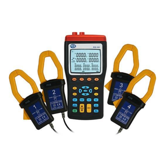
- Page 1 Tursdale Technical Services Ltd Unit N12B Tursdale Business Park Co. Durham DH6 5PG United Kingdom Phone: +44 ( 0 ) 191 377 3398 Fax: +44 ( 0 ) 191 377 3357 info@tursdaletechnicalservices.co.uk http://www.industrial-needs.com/ Manual PCE-360 power analyzer...
-
Page 2: Table Of Contents
info@tursdaletechnicalservices.co.uk CONTENTS Title Page SAFETY INFORMATION ........................1 INTRODUCTION FEATURE ......................4 III. SPECIFICATIONS ............................... 4 3-1 Environment Conditions ................................................. 4 3-2 Safety Specifications .......................... 5 3-3 General Specification ...................... 5 3-4 Electrical Specification ........................7 PARTS & CONTROLS ........................10 4-1 Description of Parts &... -
Page 3: Safety Information
info@tursdaletec chnicalservices.co o.uk 1. SAF FETY INFO ORMATION This Instru uction Manu ual provides s information n and warni ngs essenti ial for opera ating this me eter in a saf manner an nd for maint taining it in safe operat ing conditio n. - Page 4 info@tursdaletec chnicalservices.co o.uk NGER: Indica ates that inco orrect operatio on presents ex xtreme dange er of accid dent resulting in death or s erious injury to the user. ARNING: Ind dicates that in ncorrect opera ation presents s significant d danger of acc cident resultin ng in death or...
-
Page 5: Introduction Feature
info@tursdaletec chnicalservices.co o.uk CAUTION The me easurement in nput and syn nchronizing i input are not t isolated fro om each othe er. Connecti ing either on means t that the other r is exposed it is live, and d there is a d danger of ele ctric shock. -
Page 6: Specifications
Clamps, Mod del PCE AC3 360, to be use ed only with t the Three-Pha ase Power An nalyzer, Mod del PCE-360. This ma anual contains s information n and warning g that must be e followed by y the user to e... -
Page 7: Electrical Specification
PCE-360 AC C CURRENT T ADAPTOR x 4pcs Category Ra ating : CAT II II 600V per IE EC61010-1, P Pollution Deg gree2. : IEC 61 1010-1 2nd E Edition and IE EC61010-2-03 Input : AC 1 000A maxim mum. - Page 8 info@tursdaletechnicalservices.co.uk Active Power measurement P (KW) : Range Resolution Accuracy ±1.0%rdg±20dgts 999.9KW 0.1KW Display items : Active power of each channel and its sum of multiple channels. Polarity display : For influx (consumption) No symbol, For outflow (regenerative) “ - ”. Apparent Power measurement S (KVA) : Range Resolution...
- Page 9 info@tursdaletechnicalservices.co.uk Active Power Energy measurement (KWh) : Active power Range Resolution Timer interval Timer Accuracy accuracy 3.999KWh 0.001KWh 39.99KWh 0.01KWh 399.9KWh 0.1KWh ±1.0%rdg±20dgt 1 sec ±50ppm (25 ℃ , 77 ℉ ) 3.999MWh 0.001MWh 39.99MWh 0.01MWh 119.3MWh 0.1MWh Measurement display : Display all active power consumption energy (sum of absolute values). Apparent Power Energy measurement (KVAh) : Apparent power Range...
-
Page 10: Parts & Controls
info@tursdaletechnicalservices.co.uk IV. PARTS & CONTROLS 4-1 Description of Parts & Control keys... - Page 11 info@tursdaletec chnicalservices.co o.uk 1. I Input for vol ltage termina als (U1, U2, U U3, N). 2. Input for r current pro obe jacks (I1 1, I2, I3, I4). 3. Plug for external AC C adaptor pow wer supply i nput.
-
Page 12: Description Of Display
info@tursdaletechnicalservices.co.uk 4-2 Description of Display : Auto power off indication. HOLD : Display hold mode. LOCK : Set key lock mode. BT : Low battery indication. ψ: Phase angle display. : Phase angle unit. 1P2W : Measure single-phase two-wire power line indication. 1P3W : Measure single-phase three-wire power line indication. -
Page 13: Operating Instruction
info@tursdaletec chnicalservices.co o.uk Q1 : Phase e 1 reactive power measu ured display indication. Q Q2 : Phase 2 reactive p ower measured di isplay indicat tion. Q3 : Pha ase 3 reactive e power meas sured display indication. Qt : Total re eactive power r measured d display indicat... - Page 14 info@tursdaletec chnicalservices.co o.uk ※ U1 mu st be connec cted to voltag ge source du uring the mea asurement o of U2, U3, I1 , I2 and I3 , because U is the main signal l source of the whole m meter measu uring system m.
- Page 15 info@tursdaletec c hnicalservices.co o.uk Operation To use the AC Current t Adaptor, re efer to “Meas surement Con nsiderations” ” and Figure 1. 1. Connect the clamp ca able to the ins strument. 2. The arro ow on the top of the clamp must face to wards the loa...
- Page 16 info@tursdaletechnicalservices.co.uk A : Line, N : Neutral, G : Ground, Face the arrow toward the load. 1P2W Wiring Connection Diagram 1. Press key to turn on the meter. 2. Press WIRING key to select the 1P2W electrical system under test, the 1P2W annunciator will be displayed. 3.
-
Page 17: Single-Phase 3-Wire (1P3W) Power System Measurement
info@tursdaletechnicalservices.co.uk Press “ STOP” key to stop energy accumulated and the HOLD annunciator is displayed. Press ∝ key to exit the energy measurement. ※ U1 must be connected to voltage source during the measurement of U2, U3, I1, I2 and I3, because U1 is the main signal source of the whole meter measuring system. - Page 18 info@tursdaletechnicalservices.co.uk 1. Press key to turn on the meter. 2. Press WIRING key to select the 1P3W electrical system under test, the 1P3W annunciator will be displayed. 3. Connect the voltage test leads and current probe to the meter. Connect the black voltage test lead to the “N” terminal. Connect the red voltage test lead to the “U1”...
- Page 19 info@tursdaletechnicalservices.co.uk 5. Press POWER key to select (P1, Q1, S1, PF1), (P2, Q2, S2, PF2) and (Pt, Qt, St, PFt) measured values. 6. Frequency (Hz), Phase Angle (Θ ), Ground Leakage Current (I4) and Power Factor (pF) measurement : Hz : Press “Hz” key, PF1 will show “Hz”. Press “PF” key to exit. Θ...
-
Page 20: Three-Phase 3-Wire (3P3W) Power System Measurement
info@tursdaletechnicalservices.co.uk 5-4 Three-Phase 3-Wire (3P3W) Power System Measurement Application : Induction motors without adjustable speed drive. Induction motors with adjustable speed drive. Checking voltage unbalance. Checking current on phases. Checking current and current unbalance. Measuring frequency of motor current. Measuring power in 3-phase balanced and unbalanced system. -
Page 21: Three-Phase 4-Wire (3P4W) Power System Measurement
info@tursdaletechnicalservices.co.uk CAUTION If possible, before connecting the voltage test leads and current probe to the electrical equipment to be tested, take off the electrical equipment’s power. Connect the black voltage test alligator to the line “B”. Connect the red voltage test alligator to the line “A”. Connect the yellow voltage test alligator to the line “C”. - Page 22 info@tursdaletechnicalservices.co.uk 1. Press key to turn on the meter. 2. Press WIRING key to select the 3P4W electrical system under test, the 3P4W annunciator will be displayed. 3. Connect the voltage test leads and current probe to the meter. Connect the black voltage test lead to the “N” terminal. Connect the red voltage test lead to the “U1”...
- Page 23 info@tursdaletechnicalservices.co.uk Connect the black voltage test alligator to the neutral line “N”. Connect the red voltage test alligator to the line “A”. 5. Press POWER key to select (P1, Q1, S1, PF1), (P2, Q2, S2, PF2), (P3, Q3, S3, PF3) and (Pt, Qt, St, PFt) measured values.
-
Page 24: Only One Current I4 Measurement
info@tursdaletechnicalservices.co.uk 5-6 Only One Current I4 Measurement Application : Measurement any wire current independent of voltage, the same as clamp meter application. -
Page 25: Manual Data Memory And Read Function Operation
info@tursdaletechnicalservices.co.uk 1. Press key to turn on the meter. 2. Press “I4” key. 3. Connect the I4 current probe output plug to the “I4” jack. 4. Press I4 current probe trigger to open the jaw and fully enclose desired measured wire. 5. -
Page 26: Phase Sequence Measurement
info@tursdaletec chnicalservices.co o.uk 5-9 Phase Sequence Measurem 1. Press key to turn n on the mete 2. Press W WIRING key t to select 3P4W W mode. 3. Connec ct the voltage test leads to the meter. Conn nect the red vo oltage test lea ad to the “U1”... -
Page 27: Maintenance
info@tursdaletechnicalservices.co.uk VI. MAINTENANCE 6-1 General Maintenance 1. Repairs or services that are not covered in this manual should only be performed by qualified personnel. 2. Clean the meter and accessories with a damp cloth and a mild soap. Do not use abrasives, solvent, or alcohol. These may damage the text.
Need help?
Do you have a question about the PCE-360 and is the answer not in the manual?
Questions and answers