Table of Contents
Advertisement
Quick Links
Advertisement
Table of Contents

Related Manuals for PCE Instruments PCE-322-SC43


Summary of Contents for PCE Instruments PCE-322-SC43
- Page 1 SOUND LEVEL METER INSTRUCTION MANUAL...
-
Page 2: Safety Information
SAFETY INFORMATION Read the following safety information carefully before attempting to operate or service the meter. Use the meter only as specified in this manual: ⚫ Environment conditions ① Altitude lower than 2000 meters ② Relatively humidity ≤90%RH ③ Operation Ambient 0 ~ 40°C ⚫... -
Page 3: Specification
⚫ A & C Weighting ⚫ FAST & SLOW response ⚫ Analog AC/DC outputs for connection to frequency analyzer or X-Y shaft recorder 3. SPECIFICATION Standard applied: IEC61672 -1 CLASS2 Accuracy:±1.4dB Frequency range:31.5HZ ~ 8KHZ Dynamic range:50dB Memory:32700 Level ranges: LO:30dB~80dB Med:50dB~100dB Hi:80dB~130dB Auto:30dB~130dB... - Page 4 Data output: USB data traffic Auto power off: Meter automatically shuts down after approx. 15 minutes of inactivity. Power supply: One 9V battery, 006P or NEDA1604 or IEC 6F22. Power life: About 30hours Operation temperature and humidity: 0°C~40°C,10%RH~90%RH Storage temperature and temperature: -10°C ~+60°C,10%RH~75%RH Dimension: 280 (L) x 95 (W) x 45 (H) mm Weight : 329 g...
-
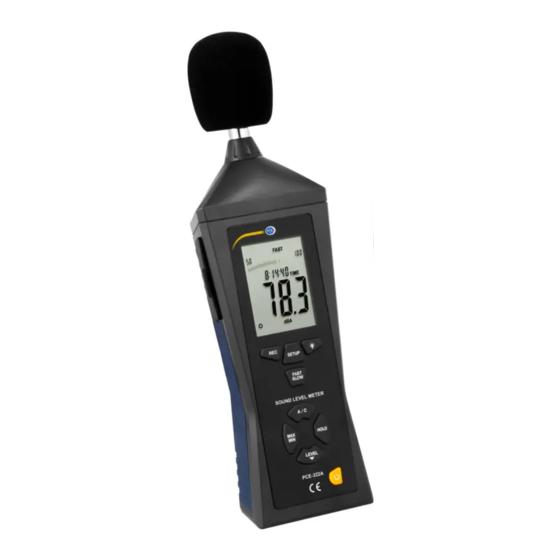
Page 5: Name And Functions
4. NAME AND FUNCTIONS When you measure at wind velocities of >10m/ s, use the wind protection on the microphone. Setup Backlight Fast/Slow A / C Max / Min Hold Level Power 10. 9 VDC power supply / mini USB interface / analogue output / calibration screw... - Page 6 MAX: Maximum indication MIN: Minimum indication OVER: Out of range indication (value too high) UNDER: Out of range indication (value too low) FAST: Fast response SLOW: Slow response dBA: A-weighting dBC: C-weighting 88 – 188 : Range selection Battery indicator: Battery low FULL: Memory full REC:...
- Page 7 DATALOGGER function Press “REC” button after it power on, the display will show “REC” to start Data Recording,press the button again to exit the record (Note: In order to avoid data error, please don’t power it off under REC condition, when the REC function is deleted then it can power off).
- Page 8 “ SETUP” button The time chip adjustment Press‘SETUP’button and then power it on,when‘TIME’ symbol displays then loosen‘SETUP’ ,the meter will be under time adjustment mode, at the time the display will show the date as following: Press the ‘SETUP’ button second time, the display showing: The display showing “minute”...
- Page 9 The display showing “hour” adjustment mode, press (h- P=P.M,h-A=A.M) ‘LEVEL’ to make the adjustment,press‘HOLD’to keep the setup; Press the‘SETUP’button fourth time, the display showing The display showing “date” adjustment mode, press ‘LEVEL’ to make the adjustment,press ’HOLD’ to keep the setup;...
- Page 10 Only if you need to factory reset the “TIME” should the following seventh step be used. Press “POWER” to end setup and restart to verify settings. Press the ’SETUP’ button seventh time to reset to factory settings, the display showing: Press ‘HOLD’...
- Page 11 Time weighting selection FAST: Fast sampling measurement, 1 time per 125mS. SLOW: Slow sampling measurement, 1 time per second. “MAX/MIN” button: Maximum and Minimum hold Press this button for one time to enter MAX/MIN measurement, ‘MAX’ will appear on LCD, maximum sound level will be captured and held until higher sound level is captured.
- Page 12 memory response, then press‘HOLD’to keep the setting. “A/C” Frequency weighting select button A:A-Weighting C:C-Weighting “HOLD” button: Press “HOLD” button, The hold function freezes the reading in the display. Power button Turn the meter power ON/OFF External DC 9V power supply terminal For connection with DC 9V power supply.
- Page 13 Software Driver Download the software via the following website: https://www.pce-instruments.com/english/download- win_4.htm Install the driver first and connect the device afterwards to the computer using the USB interface. For USB connection, observe step 8! Start your computer. Run the file „CP210xVCPInstaller.exe“ in the directory..\driver\Windows[YOUR VERSION OF THE OPERATING SYSTEM]\ with a double click.
- Page 14 The device can be switched on after the computer has restarted. Connect the device to a USB serial port. The driver will then be installed automatically and can then be found in the Device Manager of your computer. 7. If the driver is installed completely, the computer will show “CP2101 USB to UART Bridge Controller (COMX).“...
- Page 15 Software operation Symbols Open file Save data as .txt-file Save data as .xls-file Start real time measurement End real time measurement Print measurement data Information on the software version Real time measurement...
- Page 16 Start Time Beginning of the measurement series Lowest measured volume of the measurement series with the exact time Lowest measured volume of the measurement series with the exact time DataNo. Amount of measurement points Sample Rate Sampling rate Average Average sound level of the measurement series Graph Visualization as a graph...
- Page 17 In order to compare two measurement points you can set two different cursors. The data can then be analyzed.
- Page 18 Cursor A Value cursor A Max. between A and B Maximum determined value between A and B Min. between A and B Minimum determined value between A and B Cursor B Value cursor B Average between A and Measured average value between A and B Quantity between A and Measured points between A and B...
- Page 19 Function tabs The function tabs can perform more actions in addition to the functions that are described above. They help you to analyze the data: Open: open file Save as: save data in .txt-format Export To Excel: save data in .xls.-format Print Graph: print graph Print Data: print table Exit: close software...
- Page 20 Setup: set sampling rate and maximum measurement value Read out internal data logger Manual: Choose communication interface manually Auto: Choose communication interface automatically ToolBar: activate / deactivate symbol bar StatusBar: activate / deactivate status bar Color Setting: Change the colour of the graph, background or grid Contents: Run help function About: Show information on the software version.
-
Page 21: Calibration Procedures
AC: Output voltage: 1Vrms corresponding to each range step. Output impedance: 100Ω DC: Output voltage: 10mV/dB Output impedance: 1kΩ CALIBRATION PROCEDURES ① Make the following switch settings: Frequency weighting: A-weighting Time weighting: FAST Level range: 50 ~100dB ② Insert the microphone housing carefully into the 1/2 inch insertion hole of the calibrator(94dB @ 1kHZ). -
Page 22: Measurement Preparation
MEASUREMENT PREPARATION ① Remove the battery cover on the back and put in one 9V battery. ② Recover the back cover. ③ When battery voltage drops below the operating voltage or battery aging, this symbol will appear on LCD. Replace the 9V battery. ④... - Page 23 1 x wind protection 1 x screwdriver 1 x AC power adaptor 1 x 9 V battery 1 x downloadable software (PCE instruments downloads) 1 x USB cable 1 x mini tripod 1 x carrying case 1 x user manual...
- Page 24 We either re-use them or give them to a recycling company which disposes of the devices in line with law. For countries outside the EU, batteries and devices should be disposed of in accordance with your local waste regulations. If you have any questions, please contact PCE Instruments.
Need help?
Do you have a question about the PCE-322-SC43 and is the answer not in the manual?
Questions and answers