Table of Contents
Advertisement
Printed Matter No. 9836 5819 01
Publication Date 2018-02-23
Valid for Version No. 1.2
Read all safety warnings and instructions
Failure to follow the safety warnings and instructions may result in
electric shock, fire and/or serious injury.
Save all warnings and instructions for future reference
TPS Control
WARNING
Control and drive unit
User Guide
Advertisement
Table of Contents

Subscribe to Our Youtube Channel
Related Manuals for Atlas Copco TPS Control


Summary of Contents for Atlas Copco TPS Control
- Page 1 TPS Control Printed Matter No. 9836 5819 01 Control and drive unit Publication Date 2018-02-23 Valid for Version No. 1.2 User Guide WARNING Read all safety warnings and instructions Failure to follow the safety warnings and instructions may result in electric shock, fire and/or serious injury.
-
Page 2: Table Of Contents
Operation ...................... 27 Quick guide.................. 27 Job handling .................. 27 Maintenance .................... 30 Firmware updates................ 30 Reference ....................... 31 I/O configuration .................. 31 Parameters .................. 32 Licence handling.................. 43 Pneumatic function ................ 43 Barcode function.................. 47 Reporting function ................ 49 Printout .................... 49 © Atlas Copco Industrial Technique AB - 9836 5819 01... -
Page 3: User Guide
TPS Control is used for controlling and monitoring the tightening sequences and positioning operations for a variety of pneumatic and electronic tools. The TPS Control system is designed for the modern assembly industry with high demands on quality and production efficiency, and offers full modularity through the combination of different hardware and software. -
Page 4: Tps Controller
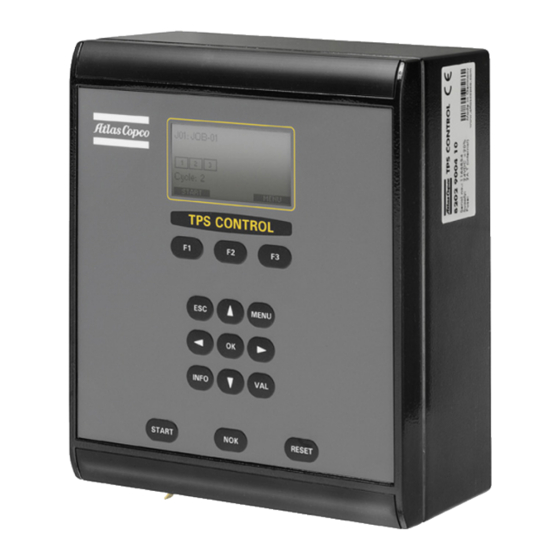
TPS controller The main part of the TPS Control system is the TPS controller. It is contained in a metal casing with a front panel and connection interface on the short side of the unit. The front panel can be rotated 180 de- grees to house the connections on the top or the bottom of the unit, depending on how the controller will be installed. - Page 5 Use these keys to display parameter options or to create/remove posi- tions when programming new jobs. INFO Press this key to get information about the TPS Control device ID, firmware version and activated licensed functions. START Use this key to start selected job.
- Page 6 Analogue input Analogue GND Not connected SSI encoder connection SSI interface with a 7-pole connection for the SSI encoder. Use a 7-pole pin plug from the Binder 680 Se- ries. © Atlas Copco Industrial Technique AB - 9836 5819 01...
- Page 7 24 V GND Power supply The TPS Control is powered by an external 24-volt power supply unit. The external power supply unit can be ordered as an accessory from Atlas Copco. As an alternative, the unit can be supplied with 24 VDC from an external power signal through the I/O plug.
-
Page 8: Toolstalk Tps
ToolsTalk TPS is a Microsoft Windows application that simplifies setup of the system. Only the main func- tions needed for setting up the system are available in ToolsTalk TPS. The complete set of functions and parameters is available in the TPS controller. © Atlas Copco Industrial Technique AB - 9836 5819 01... -
Page 9: Setup
Enter values for additional parameters. The parameters and options are described in detail in section System Parameters [Page 000]. Press VAL to confirm changes or ESC to quit without making any changes. © Atlas Copco Industrial Technique AB - 9836 5819 01... - Page 10 Note that the input signals in the tool controller correspond to the output signals for TPS control, and the relays in the tool controller correspond to the input signals in TPS Control. For a complete parameter list, see section Parameters, Input Configuration and Output Configuration.
- Page 11 Go to Service>Test functions>Test inputs to check that the fully retracted arm has an analogue en- coder value of 100. For information on how to set the encoder value to 100, see the applicable torque arm instructions. © Atlas Copco Industrial Technique AB - 9836 5819 01...
-
Page 12: Connecting Tps To Tool Control Systems
Connecting to Power Focus 4000 This section describes how to configure Power Focus 4000 and TPS Control to set up communication be- tween the controllers. Power Focus has four relay contacts (outputs) and four inputs that can be used for communication with TPS. - Page 13 In Select Source, set Pset to Digin to enable TPS to control which Pset to use. Click Store. In PF Map, select Accessories>Digital I/O and double-click Configuration. Set PF input signals in Digital Input and PF output signals in Relay according to the figure below. © Atlas Copco Industrial Technique AB - 9836 5819 01...
- Page 14 Press ESC to leave the menu. Connecting to Power Focus 600/Power Focus 6000 This section describes how to configure Power Focus 600/Power Focus 6000 and TPS Control to set up communication between the controllers. Power Focus has four relay contacts (outputs) and four inputs that can be used for communication with TPS.
- Page 15 Input 2 = Select input bit 0 ■ Input 3 = Select input bit 1 ■ Input 4 = Select input bit 2 Click OK to store all selected values in memory. In TPS Control © Atlas Copco Industrial Technique AB - 9836 5819 01...
- Page 16 Connecting to Tensor DS Drive D312 or DL Drive D313 This section describes how to configure Tensor DS/DL Drive D312/D313 and TPS Control to set up com- munication between the controllers. Tensor DS/DL Drive D312/D313 has four relay contacts (outputs) and four inputs that can be used for communication with TPS.
- Page 17 Press ESC to leave the menu. Go to Output Configuration and set the signals matching the input signals in the tool controller. Press VAL to confirm the selection. Press ESC to leave the menu. © Atlas Copco Industrial Technique AB - 9836 5819 01...
- Page 18 TPS Control Connecting to MicroTorque G4 This section describes how to configure MicroTorque G4 and TPS Control to set up communication be- tween the controllers. MicroTorque G4 has predefined outputs and inputs that can be used for communi- cation with TPS. For a complete instruction of MicroTorque G4, see the MicroTorque System user guide.
- Page 19 Press ESC to leave the menu. Connecting to MTF 400 This section describes how to configure MTF 400 and TPS Control to set up I/O communication between the controllers. MTF 400 has several digital relay outputs and inputs that can be used for communication with TPS.
- Page 20 Go to Output Configuration and set the output signals matching the input signals in the tool con- troller. Press VAL to confirm the selection. Press ESC to leave the menu. © Atlas Copco Industrial Technique AB - 9836 5819 01...
- Page 21 User guide Connecting to MTF 6000 This section describes how to configure MTF 6000 and TPS Control to set up I/O communication between the controllers. MTF 6000 has several digital relay outputs and inputs that can be used for communication with TPS.
- Page 22 Press ESC to leave the menu. Connecting to EBL RE-Drive This section describes how to configure EBL RE-Drive and TPS Control to set up communication between the controllers. All digital inputs and outputs can be configured in the EBL RE-Drive controller. For a com- plete instruction of EBL RE-Drive, see the applicable EBL user guide.
- Page 23 All digital inputs and outputs are configured in the TPS. To set up I/O communication between TPS and the tool, use the following procedure: In TPS Control Go to Menu>Setup>Input Configuration and set the input signals as seen in the figure below. © Atlas Copco Industrial Technique AB - 9836 5819 01...
-
Page 24: Installing An I/O Extension Board
When using the additional I/O board as an I/O extension board, make sure the board is equipped with jumpers (in closed position). Disconnect the flat band cable from the original I/O board for easier connection of the additional I/O board. © Atlas Copco Industrial Technique AB - 9836 5819 01... - Page 25 Connect the flat band cable from the I/O boards to the leftmost connector on the main board. Put the front panel back in the controller casing. Tighten the front panel with the screws. Put the protective strips back on the front panel. © Atlas Copco Industrial Technique AB - 9836 5819 01...
- Page 26 User guide TPS Control © Atlas Copco Industrial Technique AB - 9836 5819 01...
-
Page 27: Operation
When at least one job is programmed, you can activate the job menu by pressing the Menu key. This can only be done if no job is currently running. Pressing the Menu key displays the following selection menu in the bottom line: © Atlas Copco Industrial Technique AB - 9836 5819 01... - Page 28 To select this job, press START (F1). The job can also be started after an external start signal if the controller is connected to any external devices. See section Parameters for more details. © Atlas Copco Industrial Technique AB - 9836 5819 01...
- Page 29 Pset values can be subsequently changed for the specific positions. ■ MORE opens another menu, from which you can change the job name or completely delete a job. ■ Edit Job Name © Atlas Copco Industrial Technique AB - 9836 5819 01...
-
Page 30: Maintenance
Completely removes a job. You will be asked to confirm the removal. Press OK to confirm. Maintenance Firmware updates TPS Control provides two different options for updating the firmware in the TPS controller: ■ Initiating firmware update from ToolsTalk TPS ■... -
Page 31: Reference
This section gives an example of how to set up I/O communication between TPS and Power Focus. Recommended cable: 4222 1715 xx (03 = 3 m, 10 = 10 m) TPS I/O Power Focus I/O Output 1 (Pin 2) Tool Enable, normally closed (Pin 13/14) © Atlas Copco Industrial Technique AB - 9836 5819 01... -
Page 32: Parameters
The system parameters, as well as a number of special functions, can be accessed from the Setup menu. To facilitate navigation, the Setup menu is divided into the following subgroups: ■ System parameter ■ Input configuration ■ Output configuration © Atlas Copco Industrial Technique AB - 9836 5819 01... - Page 33 This parameter is only visible if the activation code for Default: Electric air tools has been entered. Position control No = TPS Control is used without a torque arm (TPS No/Yes Control is only used as counter) Default: Yes Yes = TPS Control is used with a torque arm (counter...
- Page 34 R=100%, G=0%, and B=0%. 100% Default: 50% RGB portion Green See RGB portion Red 100% Default: 50% RGB portion Blue See RGB portion Red 100% Default: 50% © Atlas Copco Industrial Technique AB - 9836 5819 01...
- Page 35 ---, IN-1-IN-10 tion. Default: --- If this input is set, the corresponding button on the TPS keyboard is deactivated. Only applicable if NOK acknowledge = Yes in the Se- quence menu © Atlas Copco Industrial Technique AB - 9836 5819 01...
- Page 36 Default: --- conditions are met. Out in position Changes to active as soon as a specified position has ---, OUT-1...OUT-6 been reached. Default: --- © Atlas Copco Industrial Technique AB - 9836 5819 01...
- Page 37 Job always starts, when the input signal is high ■ Continuous To start a job requires a rising edge. Also, the start signal must be available during the entire opera- tion (otherwise the operation will end) © Atlas Copco Industrial Technique AB - 9836 5819 01...
- Page 38 500 ms after being Default: hold available once. ■ hold The system waits until the signal returns ■ abort The system interrupts this cycle with NOK © Atlas Copco Industrial Technique AB - 9836 5819 01...
- Page 39 The length varies depending on the arm type. For more information, see section Set up TPS. SSI coding Defines the coding method used for the SSI Interface Binary, Gray Default: Binary © Atlas Copco Industrial Technique AB - 9836 5819 01...
- Page 40 Barcode input Parameter name Description Range/Values Format label data Opens a submenu. Define new code Opens a submenu. © Atlas Copco Industrial Technique AB - 9836 5819 01...
- Page 41 Sets the number of characters used for the part of the 0-32 barcode defined as Id2 Default: 0 Id2 position Position of first character for reporting string Id2 (ex- 1-128 tracted from the Barcode) Default: 1 © Atlas Copco Industrial Technique AB - 9836 5819 01...
- Page 42 Prints a plain text list of all setup parameters on the serial interface Print jobs Prints a plain text list of all jobs on the serial interface Print all Prints all parameters and all jobs on the serial inter- face © Atlas Copco Industrial Technique AB - 9836 5819 01...
-
Page 43: Licence Handling
Options lists the available licence numbers. Pneumatic function TPS Control can be used with a pneumatic system for evaluating the OK/NOK for each individual tighten- ing operation. This is done using a double sensor system (with digital inputs) connected to the air tool. In addition to positioning, TPS Control counts all correct tightenings in a batch and detects for example pre- mature shut-off, stripped threads and wrong screw length. - Page 44 For TPS Control to function properly with air tools, it requires a stable air-line system without too much pressure fluctuations. You must therefore install a pressure gauge as close as possible to the TPS pneu- matic system and for an optimal air signal, make sure the air cable length is no more than two meters.
- Page 45 Connect the I/O cable to the TPS Control. Connect the analogue encoder and SSI encoder to the TPS Control. Connect the external power supply unit to the TPS Control and the power mains. Programming pressure sensors Before programming the pressure sensors, you must connect the tool directly to the air-line supply, by- passing the magnetic valve.
- Page 46 Troubleshooting If the tightening is rated NOK, one of the error messages in the table below appears in the TPS control display. Check that the air option parameters are adjusted in accordance with the actual work piece.
-
Page 47: Barcode Function
The TPS Control has two RS-232 serial ports to connect the unit to a PC and a barcode reader. Since both RS-232 interfaces are available on the same Sub-D 9-pin connector, a Y-cable adapter must be used if the barcode scanner and the PC connection are to be used at the same time. - Page 48 By setting the parameter Label in the menu Sequence it can be determined whether a new label must be read in for every start, or if the previous job selection will continue when starting without a new label. © Atlas Copco Industrial Technique AB - 9836 5819 01...
-
Page 49: Reporting Function
TPS Control User guide A read-in label will be shown in the display of the TPS Control if it cannot be processed. A total of 200 la- bels can be used in TPS Control. All label data can also be printed out with the Print function. - Page 50 Select the same rate as used in the TPS from the drop-down menu Bits per second. Click Apply and then OK. In TPS Control, go to the submenu Print-out in Service. Choose whether you want to print parameters, jobs or all collected information.
- Page 51 In PC, select Transfer>Capture Text. A new window will appear. Name the text file and choose a location in which to store it. Click Start. In TPS Control, go to the submenu Print-out in Service. Determine whether you want to print parameters, jobs or all collected information.
- Page 52 Original instructions Atlas Copco Industrial © Copyright 2018, Atlas Copco Industrial Technique AB. All rights reserved. Any Technique AB unauthorized use or copying of the contents or part thereof is prohibited. This SE-10523 STOCKHOLM applies in particular to trademarks, model denominations, part numbers and drawings.
Need help?
Do you have a question about the TPS Control and is the answer not in the manual?
Questions and answers