Table of Contents
Advertisement
Quick Links
Advertisement
Table of Contents
Troubleshooting

Subscribe to Our Youtube Channel
Related Manuals for Atlas Copco ECO Zc1510


Summary of Contents for Atlas Copco ECO Zc1510
- Page 1 ECO CONTROLLER USER MANUAL Draft version 1.6...
-
Page 2: Table Of Contents
Contents General .................................. 6 1.1. 1-View ................................... 6 Main side tabs ............................... 6 2.1. Home ................................. 6 2.2. Control ................................8 2.2.1. Inverter ................................9 2.2.2. Input Selector ..............................9 2.2.3. Remote Start ..............................9 2.2.4. Input Limit ..............................10 2.2.5. - Page 3 2.8.4. Mains ................................23 2.8.4.1. Mains Alarms............................23 2.8.5. Battery ................................. 24 2.8.5.1. Manual Charge Current mode (DVCC) ....................24 2.8.5.2. Battery Alarms ............................25 2.8.6. Modes & Functions ............................. 25 2.8.6.1. Series mode ............................. 26 2.8.6.2. Standby mode ............................27 2.8.6.3.
- Page 4 3.5.4. Inverter Overloaded ............................ 39 3.5.5. VE.Bus Error ..............................39 3.5.6. Inverter Fault ............................... 39 3.6. Advanced Controls Info ........................... 39 3.7. Gauges AC IN & OUT ............................40 3.8. Energy Sources ..............................40 3.9. Battery Info ..............................41 3.10. Battery Troubleshooting ..........................
- Page 5 4.3.1. Setup Instructions ............................55 4.3.2. AC Coupled mode - Operating info ......................56 Annex. AC Coupled mode: ZBP Inverter Software & External PV Inverter Setup ............56...
-
Page 6: General
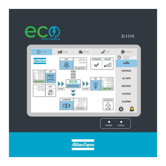
1. General 1.1. 1-View Provide the access to main side tabs which contains data, controls and information of the ECO Controller User Interface. ▪ Additional tabs are displayed with blue dotted rectangular marks that can be clicked on. Input info tab Advanced Controls Info tab Basic Controls Setup tab 2. - Page 7 The home tab shows how real-time power is efficiently distributed and what is the state of the main key components such as available energy sources, battery and output. It contains following features: ▪ ECO Controller o Status: Operational, Parking, Stand-by & OFF (see section 3.11.1).
-
Page 8: Control
▪ SOC Start in Green: If Low SOC condition to activate AC Input Source is triggered (see section 3.6). ▪ SOC Start in Grey: If Low SOC condition to activate AC Input Source is not triggered. ▪ Minimum Charge: Related to Charge Soft Start (see section 2.5) that indicates the Charging is limited to avoid initial load impact on the GenSet. -
Page 9: Inverter
▪ Additional tabs: o Advanced Controls: Summary of the internal assigned settings (see section 2.8). o Basic Controls Setup: Guide to easily setup the controls of the ZBP (see section 3.13). 2.2.1. Inverter Virtual switch to control Inverter & Solar Charge Controller ▪... -
Page 10: Input Limit
• Configurable Start / Stop Power Setpoints and Stop delay ▪ Inverter Power Start • Based on ZBP nominal power per phase • Configurable Start / Stop setpoints and Stop delay ▪ SOC Start • Based on Battery SOC (State of Charge) •... -
Page 11: Auxiliary Output Timer
▪ Programmed Time Control Click on the calendar widget to add timers as shown below. Time format period is 24h. A tick is displayed on the day that a timer has been added. If no timers are added, the Timer Start condition is OFF. ▪... -
Page 12: Ac Info
Same function as on Remote Control, where the calendar widget allows the user to add up to three times per day every day of the week. If timers are added, the Auxiliary Output will enable only during timer period, and will be disabled the rest of the time during that day. -
Page 13: Ac Output Info
▪ Remote Start o Power Start: Auto condition to Start/Stop the AC Input Source based on Output Power. o SOC Start: Auto condition to Start/Stop the AC Input Source based on Battery SOC. o Timer Start: Auto condition to Start/Stop the AC Input Source based on timers. ▪... -
Page 14: System
▪ Battery Data o DC Power (+ charging / - discharging) o Voltage: Battery DC bus voltage (V) o Current: Battery DC bus current (+ charging/- discharging) o Temperature: Average battery bank temperature (°C or °F). o State of Health: It is a measurement that indicates the level of degradation and remaining capacity of the battery bank. -
Page 15: Alarms
▪ Machine Information: Shows specific information of your ZBP unit. ▪ Service: Password protected tab for Atlas Copco service. ▪ Power Connect: QR code for easy access to repair parts after entering the serial number of the ZBP. https://powerconnect.atlascopco.com ▪... -
Page 16: Alarms Log
▪ Input (see section 3.2). ▪ Battery (see section 3.10). ▪ Inverter (see section 3.5). ▪ System (see section 3.11). 2.7. Alarms log Logging of real-time and historical information on internal events, warnings and alarms, where users can check when they were triggered and cleared. -
Page 17: How To Activate Or Deactivate Functions
Note that the ECO Controller will reset itself to update the changes once the user clicks on SAVE button. Do not proceed if ZBP is in operation mode. An overview of the assigned advanced controls settings of the ZBP is located on Advanced Control Info tab (see section 3.6). -
Page 18: Deactivate Procedure
o Green check marks are shown if a function is activated. o Click on SAVE button located on the Advanced Controls landing tab to reset the ECO Controller and apply the new settings. 2.8.1.2. Deactivate procedure ▪ Restore to default all functions from a specific module o Select the module and click on Deactivate. -
Page 19: Load Dependent Start
2.8.2.1. Load Dependent Start Function to customize the setpoints of the condition to control the Remote Start signal based on total output power. This function is disabled until the Setpoint Signal ON is lowered than Inverter Start Signal ON setpoint multiplies by number of phases of the ZBP. -
Page 20: Soc Start
2.8.2.3. SOC Start Function to customize the setpoints of the condition to control the Remote Start signal based on Battery SOC. 2.8.3. GenSet Provide the customizable settings when GenSet is selected as main AC Input Source. -
Page 21: Warm Up Function
2.8.3.1. Warm Up function The user can edit the delay to synchronize the ZBP with a running Generator to increase or decrease its warm-up time before supplying power to the ZBP. Modify these settings to suit the requirements of your Generator or application. 2.8.3.2. -
Page 22: Deepsea Controller Mkii
2.8.3.3. Deepsea Controller MKII Function to allow communication with a Deepsea Controller MKII connected to the ECO Controller via rs485. The user can also determine the setpoint to trigger an alarm based on the level of fuel recorded by the Deepsea controller. A new tab is displayed with data and controls from the Deepsea device on the Home tab after activated (see section 4.1.2). -
Page 23: Mains
2.8.4. Mains Provide the customizable settings when Mains is selected as main AC Input Source. 2.8.4.1. Mains Alarms Function to customize the delays to trigger alarms related to Mains (see section 3.2.5). -
Page 24: Battery
2.8.5. Battery Provide the customizable settings related to the battery of the ZBP. 2.8.5.1. Manual Charge Current mode (DVCC) Function that allows the user to manually select a fixed maximum battery charge current and disable the automatically control of the charging power algorithm based on the size of the available GenSet. Therefore, Charge Soft Start and Downsized GenSet functions are deactivated if the Manual Charge Current mode is activated. -
Page 25: Battery Alarms
2.8.5.2. Battery Alarms Function to customize the delays to trigger alarms related to Battery. 2.8.6. Modes & Functions Allow to edit general functions and to activate and/or change settings of additional or existing operating modes of the ZBP. -
Page 26: Series Mode
2.8.6.1. Series mode Function to enable the ZBP to operate in series mode (2 units of the same models connected in series) where the user must select whether the unit is the Main (connected to the Load and controlling the GenSet) or the Follower (connected to the GenSet). -
Page 27: Standby Mode
2.8.6.2. Standby mode Function to select how long the inverters can remain on when the ZBP is idle before automatically shutting down the inverters. Default period is 2 days. -
Page 28: Fan Settings
2.8.6.3. Fan Settings Edit settings of the variable speed fan of the ZBP according to the site environment or sound requirements. ▪ Fan Limit: Following max speed limits can be selected: The selected max speed is shown on the Fan and Heater Test tab (see section 3.12). -
Page 29: Advanced Modes
o Remote Start ON => Input Switch ON o Remote Start OFF => Input Switch ON o GenSet Warm Up= Disabled o Charge Soft Start = Disabled 2.8.7. Advanced modes 2.8.7.1. AC Coupled mode It allows the connection of a photovoltaic inverter to the ZBP output, protecting the AC Input Source and the batteries in case of reverted power from the PV inverter which can damage these components. -
Page 30: Password
▪ Input revert power delay This function will open the input switch of the ZBP to avoid feeding power to AC Input Source when it is running. It is possible to add a delay up to 10s. ▪ Duration How long the input switch is open if feed-in power to AC Input Source. ▪... -
Page 31: System Settings
2.9. System Settings Edit some of the internal settings of the ECO Controller. 2.9.1. Time Settings Modify the default time settings... -
Page 32: Update
2.9.2. Update Update the ECO Controller firmware. Procedure to update the Firmware: ▪ Save the file in a USB ▪ Insert the USB in one of the USB ports available in the back of the ECO Controller ▪ Go to Updated / Select from USB and select USB Folder ▪... - Page 33 ▪ Click on the arrow to apply the update. The ECO Controller will reset itself after the update is being applied.
-
Page 34: Additional Tabs
3. Additional tabs 3.1. Input Info Provide a description of the functions related to the input of the ZBP. 3.1.1. Input Switch Info Internal switch located in the input of the inverter which is controllable by the ECO Controller. This switch must be closed to be able to synchronize the ZBP with an AC Input Source. -
Page 35: Input Functions
3.1.3. Input Functions ▪ Input Limit: see section 2.2.4. ▪ Input Sync and Input Load: see section 2.3.1. 3.2. Input Troubleshooting Instructions to clear alarms related to the AC Input Source. 3.2.1. GenSet Fail to Start Activated if GenSet is not synchronized with ZBP when Remote Start signal is ON after an assigned delay. It is disabled if Mains is selected as AC Input Source or Series mode is enabled. -
Page 36: Reverse Polarity
3.2.3. Reverse Polarity Activated if a single-phase AC Input Source is connected with live and neutral reversed when using Parking mode. Switch the AC Source wires to their corresponding side. It is disabled on 60Hz models. 3.2.4. Phase Rotation Activated if the AC Input Source wires are connected to the wrong ZBP phase input connection. Replace the phases to match the correct connections. -
Page 37: Output Info
3.4. Output Info Provide a description of how the ZBP is automatically enabling or disabling the output and auxiliary output switches. ▪ Output Switch: The main output switch of the Inverter is automatically controlled by the ECO Controller when switching the mode of the inverter based on dynamic functions to improve the lifetime of the batteries and the overall performance of the ZBP. -
Page 38: Inverter Mode, State & Active Ac Input
3.5.1. Inverter Mode, State & Active AC Input Information of the mode and status of the Inverter as state below. ▪ Inverter Modes: o 1- Charger Only: Inverter only allow to charge and does not allow to discharge if no AC Voltage is detected at the input. -
Page 39: Gateway Or Inverter Offline
▪ Proceed to reset the Gateway device (Victron Cerbo GX) by manually unplugging its power terminal. ▪ Contact Atlas Copco Service 3.6. Advanced Controls Info Provide a summary of the configurable settings and additional modes set in the Advanced Controls tab according to... -
Page 40: Gauges Ac In & Out
3.7. Gauges AC IN & OUT Provide a gauge widget style to show instantaneous values of power, voltage and current per phase of the input and output. It can be accessed from the AC Info tab. 3.8. Energy Sources This tab is accessible from the AC Info tab and contains data of the different sources used to charge the batteries in both text and graph. -
Page 41: Battery Info
3.9. Battery Info Status of the battery cells, description of the functions related to the Battery as well as other important information is displayed on this tab with direct access to advanced controls info tab to check internal settings of the battery functions and battery troubleshooting guide. -
Page 42: Battery Low Or Critically Low
3.10.1. Battery Low or Critically Low Activated if Battery SOC is below default or assigned setpoint (see section 2.8.5.2). Connect an AC Input Source to charge the battery. 3.10.2. BMS Offline Activated if communication failure with Battery BMS. Follow these steps to clear the alarm: ▪... -
Page 43: Unauthorized Battery
3.10.5. Unauthorized Battery Activated if standard battery modules are replaced by unauthorized Atlas Copco modules which may damage the rest of modules and compromise the performance of the ZBP. For this reason, the ZBP is protected with management algorithms to prevent batteries from discharging until this alarm is no longer active. -
Page 44: Rcd Trip Or Limit Switch
Follow these steps to clear the alarm: ▪ Ensure safety conditions are met. ▪ Release the emergency stop button. 3.11.3. RCD Trip or Limit Switch Activated if communication one of these devices is triggered. RCD is only available in 50Hz models. Follow these steps to clear the alarm: ▪... -
Page 45: Basic Controls Setup
3.13. Basic Controls Setup Instructions for first time users to easily setup the basic controls of the ZBP can be accessed through the Basic Controls Setup button located on the Control tab. ▪ Step 1: Select the available type of AC input Source connected to the ZBP. Note that additional certifications and/or an external certified device might be required when connecting the ZBP to Mains. -
Page 46: Historical Data
3.14. Historical Data There are four buttons at the top of the chart which provides access to historic data with graphs and values for some of the datapoints measured in the ZBP. To access the top buttons, click on available datapoints located in the main side tabs which are displayed in a rectangular format or inside a chart. -
Page 47: Energy (Battery)
Use the buttons available at the bottom of the charts to do the following actions: ▪ Arrows (left & right): navigate to previous or next days, months and years. ▪ Home: back to current day, month or year. ▪ Calendar: Pop-up calendar to select a specific day, month or year. ▪... -
Page 48: Energy (Solar)
3.16. Energy (Solar) This tab is accessible from the Home tab when the unit contain a solar charge controller and displays solar data such as total production, how much solar power have been directly consumed on the load and how much have been stored in the batteries. -
Page 49: Installation
4.1.1. Installation ▪ The communication is only possible with Deepsea Controllers that provide rs485 interfaz such as the DSE7310 MKII or DSE7410 MKII. ▪ Ensure the Deepsea Controller is updated with latest firmware. ▪ Baud rate: 9600 ▪ Slave ID: 1 ▪... -
Page 50: Deepsea - Operation Info
▪ Ensure the Deepsea Controller is communicating with the Engine via CAN by adding the corresponding address code ▪ Ensure the Remote Start of ZBP hurting connector is connected to the GenSet and the DeepSea Controller is wired up. ▪ Activate the Deepsea communication on the ECO Controller (see section 2.8.3.3). - Page 51 The Deepsea tab contains the following features: ▪ Control Mode: o Current status of the Deepsea controller: Auto, Stop or Manual. o Auto mode button => ON (green) / OFF (grey) o Stop mode button => ON (red) / OFF (grey) ▪...
-
Page 52: Series Mode
o Fuel Level Low: indicates fuel is lower than assigned value when activating Deepsea. o High Voltage Alarm: indicates the GenSet provides out of range voltage that cannot be accepted by the ZBP. Only available for 60Hz models. 4.2. Series mode Enable this mode to connect two ZBP of same model type in series to provide greater autonomy on the same installation. - Page 53 5. Turn ON Inverters and select the same Input Limit in both Main and Follower according to the GenSet Size. Check Input Limit alarm is not triggered after turning on Inverters in both units. 6. Test Remote Start in ZBP Main unit to ensure successful communication to control the Genset ▪...
-
Page 54: Series Mode - Operation Info
8. Ensure the GenSet Controller and Remote Start of the ZBP in Series Main mode are both in AUTO. 4.2.2. Series mode - Operation Info Once both units have been configured as explained in above section, the entire installation is controlled by the ZBP in Series Main mode which automatically will start/stop the GenSet according to the following conditions: ▪... -
Page 55: Ac Coupled Mode
4.3. AC Coupled mode A PV Inverter can be connected to the output of the ZBP to create an AC Coupled system in combination with the AC Input Source connected to the input of the ZBP, to directly power the loads and charge the batteries. 4.3.1. - Page 56 4.3.2. AC Coupled mode - Operating info When the ZBP is operating with disconnected AC Input Source, the output power of the PV Inverter is controlled by changing the AC output frequency of the ZBP, to protect the batteries from overcharged. When the AC Input source is running, the output frequency of the ZBP is fixed by the frequency of the AC Input Source so the ZBP cannot control the output power of the PV Inverter.
- Page 57 o Add the corresponding assistants on each inverter. o Add the PV Inverter assistant The assistant must be placed on the last position of the list and must be loaded in all inverters in the system. It will be indicated whether it is necessary in a specific inverter. ▪...
- Page 58 ▪ Nominal power of the connected external PV inverter and the total power of the connected PV panels to the external PV inverter must be added on the PV inverter assistant. 2. Setting up Fronius...
Need help?
Do you have a question about the ECO Zc1510 and is the answer not in the manual?
Questions and answers