Table of Contents
Advertisement
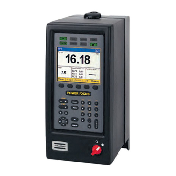
Power Focus
Quick Guide
SAFETY INSTRUCTIONS
When using electric products, basic precautions should be followed:
❑ THIS EQUIPMENT MUST BE EARTH GROUNDED
❑ Always disconnect the equipment from the mains, by pulling the
plug, before opening it for installation, service etc
❑ Do not use this product near water
Advertisement
Table of Contents

Related Manuals for Atlas Copco Power Focus 4000 Graph


Summary of Contents for Atlas Copco Power Focus 4000 Graph
- Page 1 Power Focus Quick Guide SAFETY INSTRUCTIONS When using electric products, basic precautions should be followed: ❑ THIS EQUIPMENT MUST BE EARTH GROUNDED ❑ Always disconnect the equipment from the mains, by pulling the plug, before opening it for installation, service etc ❑...
- Page 2 CONTENTS GETTING STARTED – Putting together the Tensor system – Mounting and connecting – The Compact user interface – The Graph user interface – ToolsTalk PF STRATEGIES – Setting up the normal two-stage tightening – Monitoring the fi rst stage of your tightening –...
- Page 3 Putting together the Tensor system Power Focus 4000 is the electric tool controller replacing the 3100 generation, as the control and monitoring system for Atlas Copco’s Tensor and ETX electrical tools. This advanced fastening system consists of: – a Power Focus controller. Two different hardware versions are...
- Page 4 Mounting and connecting Wall Lock Controller 1) Open the locking mechanism 2) Open the controller slowly towards you 3) Connect the tool cable, power cable etc. (see picture below) 4) Connect the RBU 5) Check that the GFI (Ground Fault Interruptor) is switched on 6) Close the controller and lock it 7) Connect the power cable to a power supply (115/230 V) 8) Turn the power on...
- Page 5 The Compact user interface 2. NOK 3. Alarm 4. AutoSet 5. n x OK 6. Job OK STAT 8. Prog Control 1. OK The tightening result is within specifi ed limits 2. NOK The tightening result is outside of specifi ed limits 3.
- Page 6 The Compact user interface Button Functionality Question mark Pressing it will show RBU type (Au = Gold, Ag = Silver etc), installed software release, connected tool type, active Pset and Job Press F (Function key) to display functions. To display function F1 press F once, to display function F2 press F twice etc.
- Page 7 The Graph user interface The color display offers easy monitoring and programming. It can be confi gured to show information from any Power Focus within a cell. The display is fully confi gurable - the picture below shows only one example. Job no.
- Page 8 ToolsTalk PF Connect via USB 1) Turn on your PC and the PF , then 2) con- nect the USB cable. Your PC should detect the PF , which makes it possible to start TTPF and connect to the PF using the ”serial” option.
- Page 9 ToolsTalk PF Connect via Ethernet continued...
- Page 10 Setting up the normal two-stage tightening Torque Control / Angle Monitoring – Two Stage To quickly get started, either make the basic settings using AutoSet a) On the Compact, this is done by i) pressing the ”arrow” button, ii) confi rming by pressing Enter, iii) entering the fi...
- Page 11 Monitoring the fi rst stage of your tightening The Power Focus offers several ways to control and monitor the rundown of the screw cycle. The rundown is the rotation before snug level (where the screw head starts compressing the joint). Rundown Monitoring: monitor the angle between cutting the fi...
- Page 12 Yield control Using Yield control as tightening strategy gives higher clamp force out of the same screw, than with Torque control. A problem joint could benefi t from a change of strategy, or it can be redesigned into smal- ler dimensions and lower weight, while meeting the same clamping requirements.
- Page 13 Detecting a ”rehit” At hand-held applications, there is always a risk that the operator starts a tightening on an already tightened bolt. This can disturb the station’s batch counting. Power Focus has a rehit detection based on tool speed in the fi rst stage, and tightening angle in the fi...
- Page 14 Setting up an accessory in W07 The setup of an accessory is very easy, using ToolsTalk PF W07 . If you click your way past Accessories in the PF Map, then I/O bus, then right-click on Confi guration, you will be led through the neces- sary steps by the program.
- Page 15 Setting up an accessory in W07 How do I trouble-shoot the Accessory? To fi nd out whether Power Focus has established communication with the Accessory, go to the I/O bus Information window. There, you can e.g. see to which Device address the unit is set. There is no longer a need to open the Accessory to check the rotary switch.
- Page 16 Logic Confi gurator Assumption: You want to use the green lamp on the Stacklight to signal a Job OK. The lamp should light up at Job OK and should come off only when you push the Stacklight button. Solution: Create a Logic Confi gurator that controls the described ”process” . It should have two Inputs –...
- Page 17 Logic Confi gurator Go to Accessory setup and program the Stacklight. The illustration shows that the output signal of our Logic Confi gurator sheet is called Logic Relay 1. We give the ”button push” signal the name Logic digin 1, see below. Back to the Logic Confi...
- Page 18 Logic Confi gurator Now store your program to the Power Focus and test it by working the Job. You might not be quite happy with the result. Why? 1. The Job OK signal is a ”long” internal signal, staying active until the next Job is activated.
- Page 19 Logic Confi gurator Comment: Compare the Job OK signal, marked ”Tracking” in the Confi gurator sheet, with the OK signal, marked ”Pulse” . The OK signal is already a 0,1 s long pulse, and would not need the conversion with the help of a Timer gate.
- Page 20 Station control using Logic Confi gurator Assumption You want to control a work station, to fi xture the work piece with a pneumatic cylinder until the Job is OK. See the following logical wiring scheme and fl ow chart.
- Page 21 Station control using Logic Confi gurator Å Å The mechanical blocking device might require an additional, manual two-hand trigger, for personal safety reasons. The station must be realized in line with local safety regulations.
- Page 22 Station control using Logic Confi gurator Solution Denote the external signals (2 position sensors, 1 key switch) on the digital inputs with logical names, as well as the relay signal we want to create (for the air cylinder).
- Page 23 Station control using Logic Confi gurator Create the Logic Confi gurator for the air cylinder on Relay 1. It will need one input to activate the cylinder and two inputs to deactivate it (one for the key switch and one for Job OK).
- Page 24 Station control using Logic Confi gurator Create a second LoCo. With this LoCo, we simply want to trigger the Job, using the ”Work piece fi xtured” signal. Create a third LoCo, that uses the key switch signal as input (like LoCo 1 above) to abort the Job.
- Page 25 EVENT CODES Event code Group Description E001-E099 Rundown failures E100-E199 Event-related errors E200-E299 User input events E300-E399 Statistical events E400-E499 Communication events E500-E599 Hardware events TOOL E600-E699 Hardware events DC3000/MC3000 E700-E799 Hardware events E800-E899 Software events E900-E999 Events MMI3000 Event Event Text Acknow- Explanation...
- Page 26 E113 Current limit reached – The current limit has been reached; Rundown aborted. the drive is disabled E117 Tool lokal – cannot ac- Power Focus cannot communicate with cess RBU RBU and must be restarted to protect data. For more information see section Sub information for event codes.
- Page 27 E131 Tool Disconnected This error indicates that the tool is not connected to the controller or that the tool cable has been damaged. E132 Wrong tool start input 1) Check if the remote start wiring in settingt the PF is correctly set in accordance to the settings in the Confi...
- Page 28 E152 PF locked in job mode This error appears when in a forced cell job an attempt is made to tighten with a controller which is not currently active or when a controller has perfor- med all tightenings. E153 Not Ok to select A job is currently running, it is not pos- new job sible to select a new job until the fi...
- Page 29 E177 Functionality not in The user is trying to employ functiona- lity not enabled in this RBU E178 Memory allocation The user is trying to allocate more error memory than is available E179 Totally confi gurable Function not possible without ”totally memory needed confi...
- Page 30 E240 Password Incorrect The password is entered from an Input Source invalid source according to the confi guration. E250 Maxtime for fi rst tighten- This message is displayed and the job ing run out (job) is terminated if the fi rst tightening is not performed within the specifi...
- Page 31 E348 7dec x r Trend deviation alarm – the subgroup torque range has decreased 7 times in a row E349 7dec r tq Trend deviation alarm the subgroup torque range value has decreased 7 times consecutively E350 7above x tq Trend deviation alarm –...
- Page 32 E367 7dec x ang Trend deviation alarm, the subgroup angle mean value has decreased 7 times consecutively. E368 7inc r ang Trend deviation alarm, the subgroup angle range value has increased 7 times consecutively. E369 7dec r ang Trend deviation alarm, the subgroup angle mean value has decreased 7 times consecutively.
- Page 33 E386 7inc x cm Trend deviation alarm, the subgroup CM mean value has increased 7 times consecutively. E387 7dec x cm Trend deviation alarm, the subgroup CM mean value has decreased 7 times consecutively. E388 7inc r cm Trend deviation alarm, the subgroup CM range value has increased 7 times consecutively.
- Page 34 E405 IO Expander is not The I/O expander is not properly con- connected or not nected or the ID of the I/O expander is responding not the same as the one confi gured. E406 RE-alarm is not connec- The Remote alarm is not properly con- ted or not responding nected or the ID of the Remote alarm is not the same as the one confi...
- Page 35 E460 FieldBus Type Mailbox Message Fault E461 FieldBus Type Gen Com Fault E462 FieldBus Mailbox Mes- sage Fault E463 FieldBus Gen Com Fault E464 FieldBus Hardware The FieldBus module is broken and Fault has to be replaced. E465 FieldBus Dip switch Error The software tries to confi...
- Page 36 E500-E599: Hardware errors TOOL E501 Tool overheated The tool is too hot. The drive is disabled. E502 Tool service interval expired E503 Calibration date expired The calibration date has expired. E504 Tool wear indicator alarm Tool wear indicator alarm indicates that the tool should be serviced.
- Page 37 E540 Calibration not OK, Calibration not OK, calibration value CalVal changed > 5% changed > 5% of max value since last of max value since last calibration. calibration E541 Other calibration error E550 Radio contact with Radio contact with tool established, tool established, tool tool accessible.
- Page 38 E626 Dcbus Lo, 40V Restart controller. If problem still remains contact the local Atlas Copco service representative. E631 Contact card error Contact card error. Contact the local Atlas Copco service representative. E700-E799: Hardware errors E700 PF started This error code is only visible in the error log and used when the Power Focus is started.
- Page 39 E824 Cycle abort timeout No tightening result was received from the drive before the Cycle abort timeout. The Cycle Abort timer is confi gurable in the Pset. E831 Autoset wrong angle Autoset could not be executed, the angle results of the tightening performed were null.
- Page 40 E863 IP Port already in use An attempt was made to bind a TCP or UDP socket to a port already in use. For instance, a customer protocol might be using the same port as ToolsTalk. E864 Ethernet echo detected An Ethernet packet was discarded, since its source MAC address was equal to the PF’s own MAC address.
- Page 42 www.atlascopco.com...
Need help?
Do you have a question about the Power Focus 4000 Graph and is the answer not in the manual?
Questions and answers
please help