Table of Contents
Advertisement
Quick Links
Industrial Automation Headquarters
Taiwan:
Delta Electronics, Inc.
Taoyuan Technology Center
No.18, Xinglong Rd., Taoyuan District,
Taoyuan City 33068, Taiwan
TEL: +886-3-362-6301 / FAX: +886-3-371-6301
Asia
China:
Delta Electronics ( Shanghai ) Co., Ltd.
No.182 Minyu Rd., Pudong Shanghai, P.R.C.
Post code : 201209
TEL: +86-21-6872-3988 / FAX: +86-21-6872-3996
Customer Service: 400-820-9595
Delta Electronics ( Japan ) , Inc.
Japan:
Industrial Automation Sales Department
2-1-14 Shibadaimon, Minato-ku
Tokyo, Japan 105-0012
TEL: +81-3-5733-1155 / FAX: +81-3-5733-1255
Korea:
Delta Electronics ( Korea ) , Inc.
1511, 219, Gasan Digital 1-Ro., Geumcheon-gu,
Seoul, 08501 South Korea
TEL: +82-2-515-5305 / FAX: +82-2-515-5302
Delta Energy Systems ( Singapore ) Pte Ltd.
Singapore:
4 Kaki Bukit Avenue 1, #05-04, Singapore 417939
TEL: +65-6747-5155 / FAX: +65-6744-9228
Delta Electronics ( India ) Pvt. Ltd.
India:
Plot No.43, Sector 35, HSIIDC Gurgaon,
PIN 122001, Haryana, India
TEL: +91-124-4874900 / FAX: +91-124-4874945
Thailand:
Delta Electronics ( Thailand ) PCL.
909 Soi 9, Moo 4, Bangpoo Industrial Estate ( E.P.Z ) ,
Pattana 1 Rd., T.Phraksa, A.Muang,
Samutprakarn 10280, Thailand
TEL: +66-2709-2800 / FAX: +66-2709-2827
Delta Electronics ( Australia ) Pty Ltd.
Australia:
Unit 20-21/45 Normanby Rd., Notting Hill Vic 3168, Australia
TEL: +61-3-9543-3720
Americas
USA:
Delta Electronics ( Americas ) Ltd.
5101 Davis Drive, Research Triangle Park, NC 27709, U.S.A.
TEL: +1-919-767-3813 / FAX: +1-919-767-3969
Brazil:
Delta Electronics Brazil Ltd.
Estrada Velha Rio-São Paulo, 5300 Eugênio de
Melo - São José dos Campos CEP: 12247-004 - SP - Brazil
TEL: +55-12-3932-2300 / FAX: +55-12-3932-237
Mexico:
Delta Electronics International Mexico S.A. de C.V.
Gustavo Baz No. 309 Edificio E PB 103
Colonia La Loma, CP 54060
Tlalnepantla, Estado de México
TEL: +52-55-3603-9200
*We reserve the right to change the information in this manual without prior notice.
EMEA
EMEA Headquarters:
Delta Electronics ( Netherlands ) B.V.
Sales: Sales.IA.EMEA@deltaww.com
Marketing: Marketing.IA.EMEA@deltaww.com
Technical Support: iatechnicalsupport@deltaww.com
Customer Support: Customer-Support@deltaww.com
Service: Service.IA.emea@deltaww.com
TEL: +31 ( 0 ) 40 800 3900
BENELUX:
Delta Electronics ( Netherlands ) B.V.
Automotive Campus 260, 5708 JZ Helmond, The Netherlands
Mail: Sales.IA.Benelux@deltaww.com
TEL: +31 ( 0 ) 40 800 3900
Delta Electronics ( Netherlands ) B.V.
DACH:
Coesterweg 45, D-59494 Soest, Germany
Mail: Sales.IA.DACH@deltaww.com
TEL: +49 ( 0 ) 2921 987 0
Delta Electronics ( France ) S.A.
France:
ZI du bois Challand 2, 15 rue des Pyrénées,
Lisses, 91090 Evry Cedex, France
Mail: Sales.IA.FR@deltaww.com
TEL: +33 ( 0 ) 1 69 77 82 60
Iberia:
Delta Electronics Solutions ( Spain ) S.L.U
Ctra. De Villaverde a Vallecas, 265 1º Dcha Ed.
Hormigueras – P.I. de Vallecas 28031 Madrid
TEL: +34 ( 0 ) 91 223 74 20
Carrer Llacuna 166, 08018 Barcelona, Spain
Mail: Sales.IA.Iberia@deltaww.com
Delta Electronics ( Italy ) S.r.l.
Italy:
Via Meda 2–22060 Novedrate ( CO )
Piazza Grazioli 18 00186 Roma Italy
Mail: Sales.IA.Italy@deltaww.com
TEL: +39 039 8900365
Russia:
Delta Energy System LLC
Vereyskaya Plaza II, office 112 Vereyskaya str.
17 121357 Moscow Russia
Mail: Sales.IA.RU@deltaww.com
TEL: +7 495 644 3240
Delta Greentech Elektronik San. Ltd. Sti. ( Turkey )
Turkey:
Şerifali Mah. Hendem Cad. Kule Sok. No:16-A
34775 Ümraniye – İstanbul
Mail: Sales.IA.Turkey@deltaww.com
TEL: + 90 216 499 9910
MEA:
Eltek Dubai ( Eltek MEA DMCC )
OFFICE 2504, 25th Floor, Saba Tower 1,
Jumeirah Lakes Towers, Dubai, UAE
Mail: Sales.IA.MEA@deltaww.com
TEL: +971 ( 0 ) 4 2690148
AS-0242920-02
2022-11-07
ASRTU-EC16AP1TA
EtherCAT Remote
Communication Module
Operation Manual
w w w. d e l t a w w. c o m
Advertisement
Table of Contents

Related Manuals for Delta ASRTU-EC16AP1TA


Summary of Contents for Delta ASRTU-EC16AP1TA
- Page 1 Mail: Sales.IA.RU@deltaww.com 5101 Davis Drive, Research Triangle Park, NC 27709, U.S.A. TEL: +7 495 644 3240 TEL: +1-919-767-3813 / FAX: +1-919-767-3969 Delta Greentech Elektronik San. Ltd. Sti. ( Turkey ) Turkey: Brazil: Delta Electronics Brazil Ltd. Şerifali Mah. Hendem Cad. Kule Sok. No:16-A Estrada Velha Rio-São Paulo, 5300 Eugênio de...
-
Page 2: Table Of Contents
Adding ASRTU-EC16AP1TA and Right-Side Extension Modules ......5-2 5.2.1 Manually Adding ASRTU-EC16AP1TA and Right-Side Extension Modules .... 5-2 5.2.2 Using Auto Scan Function to Add ASRTU-EC16AP1TA and Right-Side Modules ..5-6 Operation Mode Setup ..................5-8 PDO Configuration ..................5-8 Startup Parameters .................. - Page 3 6.5.2 Detected Module ID List (F050h) ............... 6-28 Chapter 7 Application Examples ............... 7-1 Using DELTA AX3 Series CPU with ASRTU-EC16AP1TA ......... 7-4 Using ASRTU-EC16AP1TA’s High-Speed Counting and Pulse Output ..... 7-10 Chapter 8 Error Diagnosis and Trouble-shooting ..........8-1 LED Indicator Diagnosis ..................
-
Page 4: Chapter 1 Preface
Chapter 1 Preface Table of Contents Explanation of Symbols in This Manual .............. 1-2 Revision History ..................... 1-2... -
Page 5: Explanation Of Symbols In This Manual
ASRTU-EC16AP1TA EtherCAT Remote Communication Module Operation Manual This manual provides an introduction to product functions, specifications, installation, basic operations and settings. This product is an OPEN TYPE device and therefore should be installed in an enclosure free of ... -
Page 6: Chapter 2 Overview
Chapter 2 Overview Table of Contents Characteristics ....................2-2 Specifications ....................2-2 Extension Modules Connectable ................ 2-5... -
Page 7: Characteristics
EtherCAT protocol, please refer to relevant references or literatures. 3. ASRTU-EC16AP1TA is defined as an EtherCAT remote slave and AS series DI/DO modules and AI/AO modules can be connected on its right side. (Note: The communication module and positioning module are not allowed to connect on the right side of ASRTU-EC16AP1TA.) - Page 8 Chapter 2 Overview Item Specification Input form Direct current (sinking or sourcing) Input voltage/ current 24 VDC, 5 mA OFF→ON >15 VDC Action level ON→OFF <5 VDC X0.0~X0.3: < 2.5 us OFF→ON X0.4~X0.7: < 20 us Response time X0.0~X0.3: < 2.5 us ON→OFF X0.4~X0.7: <...
- Page 9 ASRTU-EC16AP1TA EtherCAT Remote Communication Module Operation Manual Item Specification Transmission medium Cat 5 or above shielded cable Transmission distance 100 m Topology structure Linear topology Environmental Specification Item Specification ESD(IEC 61131-2, IEC 61000-4-2): 8KV Air Discharge, 6KV Contact Discharge EFT(IEC 61131-2, IEC 61000-4-4): Power Line: 2KV, Digital...
-
Page 10: Extension Modules Connectable
Chapter 2 Overview Extension Modules Connectable Digital input and output modules connectable to ASRTU-EC16AP1TA and their specifications Default I/O mapping data DI/DO module (Model name) (EtherCAT master → ASRTU-EC16AP1TA) (ASRTU-EC16AP1TA → EtherCAT master) AS08AM10N 8 bits AS08AN01P 8 bits... - Page 11 ASRTU-EC16AP1TA EtherCAT Remote Communication Module Operation Manual Default I/O mapping data Special module (Model name) (EtherCAT master → ASRTU-EC16AP1TA) (ASRTU-EC16AP1TA→EtherCAT master) AS06RTD-A 14 words AS04TC-A 10 words AS08TC-A 18 words AS02LC-A 1 word 7 words...
-
Page 12: Chapter 3 Profile And Parts
Chapter 3 Profile and Parts Table of Contents Profile and Dimensions ..................3-2 Parts ......................3-2 Definition of EtherCAT Port Pins ................ 3-4 Address Switches.................... 3-4 Extension Module Port ..................3-4... -
Page 13: Profile And Dimensions
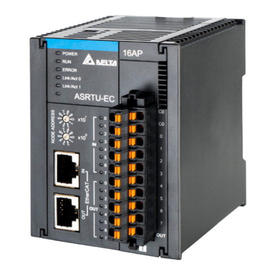
ASRTU-EC16AP1TA EtherCAT Remote Communication Module Operation Manual Profile and Dimensions Unit: mm Parts Number Name Description Model Name Model name of the module... - Page 14 Chapter 3 Profile and Parts Number Name Description Indicates the status of the power supply POWER LED indicator ON: The power is on. (Blue) OFF: No power ON: The module is in EtherCAT Operational status. OFF: The module is in EtherCAT Initial status. Blinking: Run LED indicator 1.
-
Page 15: Definition Of Ethercat Port Pins
Negative pole for receiving data Reserved Reserved Reserved Reserved Address Switches The switches are used for setting up the node address of ASRTU-EC16AP1TA in the EtherCAT network. Switch setting Description 0 ~ 99 EtherCAT node address Example: If you need to set the node address of ASRTU-EC16AP1TA to 26, simply switch the corresponding... -
Page 16: Chapter 4 Installing And Wiring
Chapter 4 Installing and Wiring Table of Contents Installing ASRTU-EC16AP1TA and AS Extension Modules to DIN Rail ..... 4-2 Connecting EtherCAT Ports ................4-3 Wiring ......................4-3 4.3.1 Power Input ....................4-3 4.3.2 Ground ..................... 4-4 Input and Output Wiring .................. 4-5 4.4.1 External Input Wiring ................. -
Page 17: Installing Asrtu-Ec16Ap1Ta And As Extension Modules To Din Rail
Installing ASRTU-EC16AP1TA and AS Extension Modules to DIN Rail Please push the clips of ASRTU-EC16AP1TA in the directions indicated by arrow ① until you hear a click. That means the DIN clips are interlocked each other. Then insert the module hooks at the bottom into the DIN rail mounting slot until you hear a click. -
Page 18: Connecting Ethercat Ports
There is a strict network topology requirement for the EtherCAT network. The network must follow the rule that the input port of the next ASRTU-EC16AP1TA must be connected to the output port of the current ASRTU-EC16AP1TA. Using Delta cables for EtherCAT communication is recommended. For specifications of Delta cables, ... -
Page 19: 4.3.2 Ground
ASRTU-EC16AP1TA EtherCAT Remote Communication Module Operation Manual ASRTU-EC16AP1TA Safety Circuit Wiring AC power supply: 100~240VAC; 50/60 Hz Power supply circuit protection fuse System circuit isolation device: The electromagnetic contactor, relay and other switch can be used as the isolation device to prevent the system from becoming unstable when the power supply is discontinuous. -
Page 20: Input And Output Wiring
The e quipment can n ot be g ro unded in this way . Input and Output Wiring 4.4.1 External Input Wiring The input points X0.0~X0.7 of ASRTU-EC16AP1TA are direct current inputs with two types of wiring: Sinking and Sourcing. See the two types of wiring below. Sinking ... -
Page 21: 4.4.2 External Output Wiring
Int er na l Ci r cui t S /S See the relevant wiring circuit in the following figure. 4.4.2 External Output Wiring All local output points of ASRTU-EC16AP1TA are transistor outputs. The wiring circuit is shown as below. ASRTU EC16AP 1TA Load OUT0 5~30VDC 0.5A... -
Page 22: Chapter 5 Configuring In Diadesigner-Ax
Adding ASRTU-EC16AP1TA and Right-Side Extension Modules ......5-2 5.2.1 Manually Adding ASRTU-EC16AP1TA and Right-Side Extension Modules .... 5-2 5.2.2 Using Auto Scan Function to Add ASRTU-EC16AP1TA and Right-Side Modules ..5-6 Operation Mode Setup ..................5-8 PDO Configuration ..................5-8 Startup Parameters .................. -
Page 23: Software Introduction
There are two methods of adding ASRTU-EC16AP1TA and right-side extension modules to the EtherCAT master configuration. The first method is to manually add ASRTU-EC16AP1TA first and then extension modules. The second method is to use the auto-scan function of the software to add ASRTU-EC16AP1TA and its right-side extension modules. - Page 24 Chapter 5 Configuring in DIADesigner-AX 2. After the “Add Device” window is open, go to “Fieldbuses” → “Ethercat” → “Slave” → “Delta Electronics, Inc.” Find out and select “ASRTU-EC16AP1TA”, and click on the “Add Device” button.
- Page 25 ASRTU-EC16AP1TA EtherCAT Remote Communication Module Operation Manual...
- Page 26 Chapter 5 Configuring in DIADesigner-AX After that, ASRTU-EC16AP1TA is visible in the EtherCAT configuration as the following figure shows. Close the window after adding ASRTU-EC16AP1TA is finished. 3. Right-click ASRTU-EC16AP1TA and then click “Add Device…” from the pop-up menu. Then the “Add Device” window is open, where ASRTU-EC16AP1TA’s right-side extension modules are added.
-
Page 27: Using Auto Scan Function To Add Asrtu-Ec16Ap1Ta And Right-Side Modules
Using Auto Scan Function to Add ASRTU-EC16AP1TA and Right-Side Modules ASRTU-EC16AP1TA supports the function of automatically scanning for ASRTU-EC16AP1TA and right-side extension modules for easy configuration and operation. See the following steps for details. Right-click “EtherCAT_Master_SoftMotion” on the left-side list of the DIADesigner-AX software and then... - Page 28 The “Scan Devices” window pops up and automatically displays ASRTU-EC16AP1TA and its right-side extension modules which are scanned out. After the ASRTU-EC16AP1TA slave and right-side extension modules are scanned out, click “Copy All Devices to Project” button to add ASRTU-EC16AP1TA and its right-side extension modules to the EtherCAT master configuration.
-
Page 29: Operation Mode Setup
ASRTU-EC16AP1TA EtherCAT Remote Communication Module Operation Manual Operation Mode Setup With a click on “General” tab in the configuration interface of ASRTU-EC16AP1TA, users could set the mode of running ASRTU-EC16AP1TA on the General page. ASRTU-EC16AP1TA supports three operation modes of SM-Synchron, DC-Synchron and FreeRun. Users could choose one mode from them in the drop-down box as shown above. - Page 30 Apart from configuring five default TxPDO Mappings and five default RxPDO Mappings, users could also configure the parameters for each PDO Mapping in the following steps. In the main configuration interface of ASRTU-EC16AP1TA, click on “General” tab and tick the checkbox of “Enable expert settings”.
- Page 31 ASRTU-EC16AP1TA EtherCAT Remote Communication Module Operation Manual For example, to add the filter time parameter for input point X0.0 to the first RxPDO Mapping for ASRTU-EC16AP1TA, click “1st RxPDO Mapping” first and then the blank row in the PDO content area and finally click “Insert” button.
- Page 32 Chapter 5 Configuring in DIADesigner-AX Select “Digital input bit0 filter time”. Then with a click on “OK”, the parameter “Digital input bit0 filter time” is added to the RxPDO Mapping. 5-11...
-
Page 33: Startup Parameters
ASRTU-EC16AP1TA EtherCAT Remote Communication Module Operation Manual Startup Parameters The parameter values for ASRTU-EC16AP1TA and extension modules could be preset on the page of the Startup Parameters tab. When the EtherCAT master and ASRTU-EC16AP1TA make the connection successfully, the corresponding parameters will be written values into according to the data configured in the Startup Parameters tab. -
Page 34: Ethercat I/O Mapping
The first one is the EtherCAT I/O mapping page for ASRTU-EC16AP1TA itself. The second one is the EtherCAT I/O mapping page for the extension modules on the right side of ASRTU-EC16AP1TA. For example, below is the EtherCAT I/O mapping page for the right-side extension module, AS04DA_A. - Page 35 ASRTU-EC16AP1TA EtherCAT Remote Communication Module Operation Manual The third one is the Edit IO mapping page. Right-click on the slave ASRTU-EC16AP1TA and then select “Edit IO mapping” item from the pop-up menu as shown below. After that, the following page is open, where you can see corresponding PDO parameters for ASRTU-EC16AP1TA and right-side extension modules.
- Page 36 Chapter 5 Configuring in DIADesigner-AX Note: After you have modified the PDO mappings for ASRTU-EC16AP1TA, the PDO parameters for ASRTU-EC16AP1TA and extension modules would show up simultaneously on the EtherCAT I/O mapping page and the mapping devices and variables for the right-side extension modules on the Module I/O mapping page would be invalid.
- Page 37 ASRTU-EC16AP1TA EtherCAT Remote Communication Module Operation Manual MEMO 5-16...
-
Page 38: Chapter 6 Introduction Of Parameters
Chapter 6 Introduction of Parameters Table of Contents Parameter List ....................6-3 General Objects ....................6-3 6.2.1 Device Type (1000h) .................. 6-3 6.2.2 Error Register (1001h) ................6-3 6.2.3 Device Name (1008h) ................6-4 6.2.4 Hardware Version (1009h) ................6-4 6.2.5 Software Version (100Ah) ................ - Page 39 ASRTU-EC16AP1TA EtherCAT Remote Communication Module Operation Manual 6.4.4.4 Pulse Output Channel 1 CurrentPulses (3005: 05h) ..........6-18 6.4.4.5 Pulse Output Channel 1 TargetPulse (3005: 06h) ..........6-19 6.4.4.6 Pulse Output Channel 1 TargetFrequency (3005: 07h) ........6-19 6.4.4.7 Pulse Output Channel 1 Acceleration Time (3005: 08h) ........6-19 6.4.4.8...
-
Page 40: Parameter List
Error register USINT 0x00 When ASRTU-EC16AP1TA produces an alarm, you can check the cause of the error and take a corrective action for ASRTU-EC16AP1TA through the value of the parameter. See the detailed explanation of parameter values in the following table. -
Page 41: Device Name (1008H)
ASRTU-EC16AP1TA EtherCAT Remote Communication Module Operation Manual Value Explanation How to deal with Check the error information on the special modules on the right of ASRTU-EC16AP1TA and find the error cause based Right-side extension module on the error code value of the extension module. -
Page 42: Identity (1018H)
Chapter 6 Introduction of Parameters 6.2.6 Identity (1018h) The object shows the basic information of ASRTU-EC16AP1TA including vendor ID, product code, revision and serial number. See the following table for details. Supports PDO Index Subindex Name Data type Attribute Default... -
Page 43: Pdo Mapping Objects
Application Protocol over EtherCAT). 6.3.1 Receive PDO Mapping The Receive PDO mapping consists of a set of output parameters for ASRTU-EC16AP1TA and its right-side extension modules. 1600h~161Fh is the output parameter configuration set for right-side extension modules. 1600h is the output... -
Page 44: Local Parameters Objects
Index Subindex Name Attribute Default type mapping or not? 3000h Switch ID UINT 6.4.1.2 Control Word (3000:02h) The Control word parameter is the control word for ASRTU-EC16AP1TA. Data Supports PDO Index Subindex Name Attribute Default type mapping or not? 3000h... - Page 45 ASRTU-EC16AP1TA EtherCAT Remote Communication Module Operation Manual See explanation of the control word parameter values of ASRTU-EC16AP1TA in the following table. Value Description Bit0 Reserved When ASRTU-EC16AP1TA is disconnected from the master or exits from the OP state, the output values of the right-side special modules all become 0 and all output points of ASRTU-EC16AP1TA and right-side digital modules turn OFF.
-
Page 46: Digital Output (3000:03H)
Users can read the value of the parameter by configuring the parameter to a PDO or using a SDO so as to get the status of the local input points of ASRTU-EC16AP1TA. Bit0 of the parameter corresponds to local input point X0.0 of ASRTU-EC16AP1TA, Bit1 of the parameter corresponds to local input point X0.1 and so on. -
Page 47: Comlost_Rtu_Output (3000:0Eh)
6.4.1.7 COMlost_RTU_Output (3000:0Eh) When ASRTU-EC16AP1TA is disconnected from the master or exits from the OP state, and bit 1 of the control word parameter is 0, you can set the value of the local output points of ASRTU-EC16AP1TA through the parameter. -
Page 48: Counter Channel 1 Inputmode (3001: 02H)
Please connect a resistor of 2.2K ohm between the input points and S/S common terminal when the input frequency exceeds 100 kHz. 6.4.2.2 Counter channel 1 InputMode (3001: 02h) The parameter sets the input mode for counter channel 1. ASRTU-EC16AP1TA supports three input modes: single pulse, “pulse + direction” and “phase A + phase B”. Supports PDO... - Page 49 ASRTU-EC16AP1TA EtherCAT Remote Communication Module Operation Manual Pulse input Timing of counting type Pulse + direction Phase A + phase B (multiplication Phase A + phase B (multiplication Phase A + phase B (multiplication 6-12...
-
Page 50: Counter Channel 1 Countdirection (3001: 04H)
Chapter 6 Introduction of Parameters 6.4.2.3 Counter Channel 1 CountDirection (3001: 04h) The parameter can be used for specifying the direction of counting when the “single pulse input” mode is set as the pulse input mode for counter channel 1. Supports PDO Index Subindex... -
Page 51: Counter Channel 1 Errorcode (3001: 08H)
The Counter channel 2 operation parameter set contains the relevant parameters for counter channel 2 and counter channel 2 corresponds to ASRTU-EC16AP1TA’s input points: X0.2 and X0.3. The explanations of the parameters for counter channel 2 operation are identical to those for Counter channel 1 operation. -
Page 52: Pulse Output Channel 1 Operation (3005H)
Counting status for counter channel 2 6.4.4 Pulse Output Channel 1 Operation (3005h) The Pulse output channel 1 operation parameter set contains the relevant parameters for pulse output channel 1 and pulse output channel 1 corresponds to ASRTU-EC16AP1TA’s output points: Y0.0 and Y0.1. Index Subindex... -
Page 53: Pulse Output Channel 1 Motionmode (3005: 02H)
1 will start the pulse output. Note: When the communication between ASRTU-EC16AP1TA and the master is lost during the pulse output, pulse output channel 1 will stop immediately and the actual output pulse count will not be cleared to 0. - Page 54 Chapter 6 Introduction of Parameters Value Description Speed output mode: In this mode, pulse output channel 1 continuously outputs pulse signals at the set target frequency (Pulse output channel 1 TargetFrequency). Note: If the acceleration time (Pulse output channel 1 Acceleration Time) and the deceleration time (Pulse output channel 1 Deceleration Time) are both not 0, the new target frequency after being modified during the pulse output will not take effect;...
-
Page 55: Pulse Output Channel 1 Status (3005:04H)
ASRTU-EC16AP1TA EtherCAT Remote Communication Module Operation Manual Value Description Relative position output mode: In this mode, the output point Y0.0 outputs a corresponding number of pulses according to the set target pulse number (Pulse output channel 1 TargetPulses), target frequency... -
Page 56: Pulse Output Channel 1 Targetpulse (3005: 06H)
Chapter 6 Introduction of Parameters 6.4.4.5 Pulse Output Channel 1 TargetPulse (3005: 06h) The parameter specifies the target pulse number for pulse output channel 1. Supports PDO Index Subindex Name Data type Attribute Default mapping or not? Pulse output channel 1 3005h DINT TargetPulse... -
Page 57: Pulse Output Channel 1 Deceleration Time (3005: 09H)
ASRTU-EC16AP1TA EtherCAT Remote Communication Module Operation Manual As shown in the figure above, when the acceleration time and deceleration time are both not 0, there are 20 steps respectively for the acceleration and deceleration of the pulse output. The output frequency increases or decreases by 1/20 of the target frequency every step, with the unit: Hz, and the time for each step is 1/20 of the acceleration time or deceleration time with the unit: ms. -
Page 58: Pulse Output Channel 1 Outputdirection (3005: 0Bh)
A/B phase output: Y0.0 outputs phase A pulse, Y0.1 outputs phase B pulse. Note: When the mode of A/B phase output is selected, the maximum output frequency that ASRTU-EC16AP1TA supports is 100 KHz. CW/CCW: Clockwise mode and counterclockwise mode. In CW mode, Y0.0 outputs the pulse signal and Y0.1 is OFF. In CCW mode, Y0.0 is OFF and Y0.1 outputs the pulse signal. -
Page 59: Pulse Output Channel 1 Actual Motionmode (3005: 0Ch)
The Pulse output channel 2 operation parameter set contains the relevant parameters for pulse output channel 2 which corresponds to ASRTU-EC16AP1TA’s output point: Y0.2 and Y0.4. The explanations of the parameters for pulse output channel 2 are identical to those for pulse output channel 1. -
Page 60: Comlost_Domodule_Outputs (2100H~2107H)
ActualFrequency 6.4.6 COMlost_DOmodule_Outputs (2100h~2107h) When ASRTU-EC16AP1TA is disconnected from the master or exits from the OP state, and bit 1 of the control word parameter is 0, ASRTU-EC16AP1TA will control the right-side extension DO modules to output corresponding values according to the settings for the parameters below. -
Page 61: Comlost_Aomodule_Outputs (2120H~2127H)
1 of the control word parameter to 0 and the parameter DOmodule2_output1 to 16#5555 in advance. 6.4.7 COMlost_AOmodule_Outputs (2120h~2127h) When ASRTU-EC16AP1TA is disconnected from the master or exits from the OP state, and bit 1 of the control word parameter is 0, ASRTU-EC16AP1TA will write data into TxPDO parameters of special modules according to the settings for this set of parameters below. - Page 62 1 special module which has the RxPDO AOmodule1_output1 mapping, on the right side of ASRTU-EC16AP1TA when ASRTU-EC16AP1TA is disconnected from the master or exits from the OP state. This parameter stands for the value in the 2...
- Page 63 2 special module which has the RxPDO AOmodule2_output3 mapping, on the right side of ASRTU-EC16AP1TA when ASRTU-EC16AP1TA is disconnected from the master or exits from the OP state. This parameter stands for the value in the 4...
- Page 64 Before setting this set of parameters above, you need to know which one among all ASRTU-EC16AP1TA’s right-side special modules which have the RxPDO mappings is the special module to be configured, instead of knowing which one among all extension modules on the right side of the ASRTU-EC16AP1TA is the special module to be configured.
-
Page 65: Module Config Objects
6.5.2 Detected Module ID List (F050h) The parameter set consists of 32 parameters which are used to display the model code of the extension modules which are actually connected to the right side of ASRTU-EC16AP1TA. See the details as follows. - Page 66 Chapter 7 Application Examples Table of Contents Using DELTA AX3 Series CPU with ASRTU-EC16AP1TA ......... 7-4 Using ASRTU-EC16AP1TA’s High-Speed Counting and Pulse Output ..... 7-10...
- Page 67 ASRTU-EC16AP1TA EtherCAT Remote Communication Module Operation Manual This chapter describes how to configure the parameters for the ASRTU-EC16AP1TA module by means of examples. In Sections 7.1 and 7.2 is the introduction of the configuration methods for ASRTU-EC16AP1TA using together with different EtherCAT masters.
-
Page 68: Chapter 7 Application Examples
8 points for input Note: 1. Please check that the modules AS16AP11T, AS04DA_A, AS04AD_A and ASRTU-EC16AP1TA are working normally and the entire network wiring is proper. 2. For more information on AS04DA_A and AS04AD_A, please refer to relevant descriptions in "AS... -
Page 69: Using Delta Ax3 Series Cpu With Asrtu-Ec16Ap1Ta
Using DELTA AX3 Series CPU with ASRTU-EC16AP1TA Download DIADesigner-AX software from Delta official website, install it and then start the software. A new project is created by selecting the “Standard project” icon in the red box and then typing a... - Page 70 Chapter 7 Application Examples Click “OK” button to complete the setting. Afterward, select “AX-308EA0MA1T (Delta Electronics, Inc.)” in the “Device” field and one right version, and then click “OK” in the following pop-up window. The created new project is shown as below.
- Page 71 ASRTU-EC16AP1TA EtherCAT Remote Communication Module Operation Manual Double-click on “Device” in the red box above and then click on “Scan Network…” in the red box in the following window. Then the following window appears, where AX-3 series controller will be searched for automatically.
- Page 72 Right-click on “EtherCAT_Master_Softmotion” in the red box below and select “Scan For Device” from the pop-up menu to scan out the EtherCAT slave. After the scan function is enabled, the software can scan out the ASRTU-EC16AP1TA module and its right-side extension modules.
- Page 73 After the scan is complete, click “Copy All Devices to Project” to add all scanned devices to the software. After adding devices is complete, right-click on ASRTU-EC16AP1TA and select “Edit IO mapping” from the pop-up menu to view the IO mapping for ASRTU-EC16AP1TA.
- Page 74 For example, when no module channels are assigned any variables, write 255 into the %QB1 device to change all the local output points of ASRTU-EC16AP1TA to ON and then monitor the status of the local input points of ASRTU-EC16AP1TA through the %IB4 device.
-
Page 75: Using Asrtu-Ec16Ap1Ta's High-Speed Counting And Pulse Output
Select the “pulse + direction” mode as the pulse output mode for pulse output channel 1 of ASRTU-EC16AP1TA, and set the target number of output pulses to 1,000,000, the target frequency to 100 kHz, and both acceleration time and deceleration time to 1000 milliseconds. - Page 76 0V, the input point X0.0 to the output point Y0.0, and the input point X0.1 to the output point Y0.1. Setting the network configuration 1. Download and DIADesigner-AX software from Delta official website, install it and then start the software. 2. After clicking “New Project…” in the open software interface, select the “Standard project” template and then type a project name and storage location in the “New Project”...
- Page 77 ASRTU-EC16AP1TA EtherCAT Remote Communication Module Operation Manual After the above setting is complete, click the "OK" button, then select "AX-308EA0MA1T" in the “Device” field and an appropriate version in the pop-up window, and click "OK" to finish the setting here.
- Page 78 Chapter 7 Application Examples Double-click “Device” in the red box in the figure above, and then click the "Scan Network…" in the red box of the following figure. After clicking "Scan Network", a new window will pop up, where the software will automatically scan for AX-3 series controller.
- Page 79 ASRTU-EC16AP1TA EtherCAT Remote Communication Module Operation Manual After the software scans out the AX-3 controller, please select the controller, and then click "OK" button. After clicking "OK", the “Device” page will automatically display the connected controller as shown in the following figure.
- Page 80 4. Right-click on “EtherCAT_Master_Softmotion” and then select “Scan For Device” from the pop-up menu to scan for the EtherCAT slave. The “Scanned Devices” window pops up and the software automatically scans ASRTU-EC16AP1TA out after the scan function is enabled. After the scan is complete, click “Copy All Devices to Project” to add all devices which are scanned out to the software.
- Page 81 ASRTU-EC16AP1TA EtherCAT Remote Communication Module Operation Manual 5. Double-click ASRTU-EC16AP1TA to open the configuration window, where you click “Process Data” tag to open the page. On the Process Data page, select relevant PDO Mappings for pulse output channel 1 and counter channel 1 as the above figure shows.
- Page 82 Chapter 7 Application Examples 7. Double-click "ASRTU-EC16AP1TA", and then click "EtherCAT I/O Mapping" tab. On the following "EtherCAT I/O Mapping" page, you can map the parameters to corresponding program variables as shown in the figure below. Explanation of the variables in the figure above:...
- Page 83 (Target pulse number) for ASRTU-EC16AP1TA is an absolute value. When the pulse output is completed, the value of the Pulse_Output_Status variable becomes 2. At the moment, you can check whether the number of pulses counted by ASRTU-EC16AP1TA’s counter channel 1 is 1,000,000 or not.
-
Page 84: Chapter 8 Error Diagnosis And Trouble-Shooting
Chapter 8 Error Diagnosis and Trouble-shooting ASRTU-EC16AP1TA supports two diagnostic methods: LED indicator and status indication. Table of Contents LED Indicator Diagnosis ................... 8-2 Status Indication Diagnosis ................8-3... -
Page 85: Led Indicator Diagnosis
The power supply is abnormal. ASRTU-EC16AP1TA is normal Green light on The power supply is normal. Error LED Error LED indicates if there is an error in ASRTU-EC16AP1TA and right-side modules. LED status Indication How to correct ASRTU-EC16AP1TA works normally or lacks the work power. -
Page 86: Status Indication Diagnosis
EtherCAT network blinking and data exchange is happening. Status Indication Diagnosis The status indication parameter of ASRTU-EC16AP1TA, “Error register” indicates current error information for ASRTU-EC16AP1TA. See Section 6.2.2 for details on the explanation of the parameter values. - Page 87 ASRTU-EC16AP1TA EtherCAT Remote Communication Module Operation Manual MEMO...
- Page 88 Appendix A Accessories for EtherCAT Communication Table of Contents Accessories for EtherCAT Communication ............A-2...
-
Page 89: Appendix A Accessories For Ethercat Communication
ASRTU-EC16AP1TA EtherCAT Remote Communication Module Operation Manual A.1 Accessories for EtherCAT Communication Cables Figure Model Length Diameter (AWG) UC-EMC003-02A 0.3M 4#22 PVC UC-EMC005-02A 0.5M 4#22 PVC UC-EMC010-02A 1.0M 4#22 PVC UC-EMC020-02A 2.0M 4#22 PVC UC-EMC050-02A 5.0M 4#22 PVC UC-EMC100-02A 10.0M... - Page 90 Appendix B Online Firmware Upgrade Table of Contents Online Firmware Upgrade ................B-2...
-
Page 91: Appendix B Online Firmware Upgrade
1. Open the DIADesigner-AX software page, create a new project and then add ASRTU-EC16AP1TA to the EtherCAT network, as shown in the following figure: Note: Please refer to Section 5.2 for details on how to add ASRTU-EC16AP1TA to the EtherCAT network. 2. With a double click on "EtherCAT_Master_SoftMotion", open the EtherCAT master configuration interface and then deselect "Automatic restart slaves"... - Page 92 After clicking "Login", click the "Yes" button in the new pop-up window. After successful login, click the "Start" option on the "Debug" menu of the menu bar. 4. Open the configuration interface for ASRTU-EC16AP1TA, and select "Enable expert settings" in the “General” tab.
- Page 93 ASRTU-EC16AP1TA EtherCAT Remote Communication Module Operation Manual 5. Open the "Online" configuration interface for ASRTU-EC16AP1TA, click the "Bootstrap" button. After ASRTU-EC16AP1TA enters the "Bootstrap Mode" state, click the "Download..." button under the "File access via EtherCAT" field.
- Page 94 Appendix B Online Firmware Upgrade Select an online file for updating the firmare from the new interface, and then click the "Open" button. Click the "OK" button in the following pop-up window to start updating the firmware.
-
Page 95: Online Firmware Upgrade
Once the online firmware upgrade is complete, the progress bar will disappear, and then the ASRTU-EC16AP1TA will automatically restart, and the current status will change to "Init". Since the check box of "Automatic restart slaves" in the "EtherCAT_Master_SoftMotion" window has been deselected, you can reset the AX-308E by using the "Reset warm"... - Page 96 Appendix B Online Firmware Upgrade...
- Page 97 ASRTU-EC16AP1TA EtherCAT Remote Communication Module Operation Manual MEMO...
Need help?
Do you have a question about the ASRTU-EC16AP1TA and is the answer not in the manual?
Questions and answers