Table of Contents
Advertisement
Quick Links
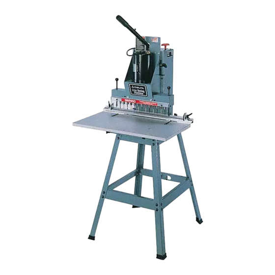
13-Spindle Line Boring Machine
13-Spindle Pneumatic Line
Model 32-325
Shown with
Accessory 32-331
Stand
To learn more about DELTA MACHINERY
visit our website at: www.deltamachinery.com.
For Parts, Service, Warranty or other Assistance,
1-800-223-7278 (
please call
Boring Machine
1-800-463-3582).
In Canada call
(Model 32-325)
(Model 32-326)
Model 32-326
Shown with
Accessory 32-331
Stand
PART NO. 449-01-651-0005 (0110)
Copyright © 2001 Delta Machinery
Advertisement
Table of Contents

Related Manuals for Delta 32-325


Summary of Contents for Delta 32-325
- Page 1 Accessory 32-331 Accessory 32-331 Stand Stand PART NO. 449-01-651-0005 (0110) Copyright © 2001 Delta Machinery To learn more about DELTA MACHINERY visit our website at: www.deltamachinery.com. For Parts, Service, Warranty or other Assistance, 1-800-223-7278 ( 1-800-463-3582). please call In Canada call...
-
Page 2: General Safety Rules
If you have any questions relative to a particular application, DO NOT use the machine until you have first contacted Delta to determine if it can or should be performed on the product. - Page 3 ADDITIONAL SAFETY RULES FOR LINE BORING MACHINE WARNING: FAILURE TO FOLLOW THESE RULES MAY RESULT IN SERIOUS PERSONAL INJURY DO NOT OPERATE THIS MACHINE UNTIL it is 12. SUPPORT WORKPIECES firmly against fence. assembled and installed according to the 13. NEVER PERFORM LAYOUT, assembly, or set-up instructions.
-
Page 4: Power Connections
POWER CONNECTIONS A separate electrical circuit should be used for your machines. This circuit should not be less than #12 wire and should be protected with a 20 Amp time lag fuse. If an extension cord is used, use only 3-wire extension cords which have 3- prong grounding type plugs and matching receptacle which will accept the machine’s plug. -
Page 5: Extension Cords
OPERATING INSTRUCTIONS FOREWORD Delta Models 32-325 & 32-326 are line boring machines. These line boring machines come with a large, 16"x29¾" table, which provides a large work space in front of the boring head for boring extra large boards. UNPACKING AND CLEANING Carefully unpack the machine and all loose items from the shipping container(s). - Page 6 LINE BORING MACHINE PARTS INSTRUCTIONS LISTED AND SHOWN IN THIS MANUAL REFER TO BOTH THE 32-325 13-SPINDLE LINE BORING MACHINE AND 32-326 13-SPINDLE PNEUMATIC LINE BORING MACHINE UNLESS OTHERWISE NOTED. WARNING: FOR YOUR OWN SAFETY, DO NOT CONNECT THE MACHINE TO THE POWER SOURCE UNTIL THE MACHINE IS COMPLETELY ASSEMBLED AND YOU HAVE READ AND UNDERSTOOD THE ENTIRE INSTRUCTION MANUAL.
- Page 7 16 - Gage for Aligning Fence to Drill Head Fig. 3 18 - Table Bracket Slides (4) For 32-325 13-Spindle Line Boring Machine 19 - Spacers (2) For 32-326 13-Spindle Pneumatic Line Boring Machine 20 - 1/4" Flat Washers (2) 21 - 1/4"...
-
Page 8: Assembly And Adjustments
Repeat this process for the three remaining holes. Fig. 7 FASTENING MACHINE TO A SUPPORTING SURFACE If you are using the boring machine without the accessory 32-331 steel stand, the machine MUST be fastened to a supporting surface using suitable hardware, not supplied by Delta. - Page 9 Fig. 8 Fig. 9 ASSEMBLING TABLE TO MACHINE 1. Clip the two table slides (A) Fig. 8, to the table bracket (B) as shown. 2. Clip the remaining two table slides to the other table bracket in the same manner. 3.
- Page 10 ASSEMBLING FENCE TO MACHINE 1. Place spacer (A) Fig. 14, over hole (B) in table bracket with large countersunk end of spacer (A) in the up position. 2. Place a 1/4" lockwasher (C) Fig. 14, and a 1/4" flat washer (D) on the 1/4-20x1-1/2" hex head screw (E) and insert screw (E) up through hole (B) in table bracket and through hole in spacer (A).
- Page 11 Fig. 18 4. With index pins (B) Fig. 18, engaged with holes in Fig. 19 gage (A), loosen table lock knobs, one of which is shown at (E), and move table until front end of fence (F) is approximately 1/32" away from gage at point (G) on each end of the gage.
- Page 12 Fig. 23 ASSEMBLING HEAD LOWERING AND RAISING HANDLE (For 32-325 Line Boring Machine Only) 1. Remove retaining ring (A) Fig. 22, and remove con- necting pin (B). 2. Insert end of handle (C) Fig. 23, into head assembly as shown and fasten handle in place by reassembling connecting pin that was removed in STEP 1, through hole in end of handle.
- Page 13 Fig. 27 Fig. 28 4. Make certain air cylinder rod is retracted completely into cylinder (E) Fig. 27. Loosen locknut (K) Fig. 27, and unscrew hex end of clevis rod (L) until holes line up with holes in bracket (N). Using retaining clip (A) and retaining pin (B), which were removed in STEP 1, fasten clevis (L) to bracket (N).
- Page 14 3. Remove jam nut (D) Fig. 31, from bottom end of air cylinder clamp (E) and assemble air cylinder clamp (E) Fig. 32, to clamp bracket (A) Fig. 31, using jam nut (D). Thread rubber foot (F) Fig. 32, onto bottom of air cylinder clamp (E) as shown.
-
Page 15: Wrench Storage
ALIGNING BORING BITS (For 32-325 Line Boring Machine Only) 1. Place a flat piece of wood (A) Fig. 37, on the table and against the fence as shown. Pull operating handle downward until ANY ONE boring bit (B) first contacts the top of the wood surface (A). - Page 16 OPERATING CONTROLS AND ADJUSTMENTS STARTING AND STOPPING MACHINE (For 32-325 Line Boring Machine Only) The switch (A) Fig. 45, is located on the top of the motor. To turn the machine “ON”, move the switch (A) to the ON position and to turn the machine “OFF”, move the switch (A) to the OFF position.
-
Page 17: Locking Switch In The "Off" Position
Fig. 48, with a 3/16" diameter shackle to prevent unauthorized use. Fig. 48 LOWERING BORING HEAD (For 32-325 Line Boring Machine Only) To lower the boring head (A) Fig. 49, pull down on handle (B). After holes have been bored, return handle to the up position. - Page 18 MULTI-POSITION LOWERING HANDLE (For 32-325 Line Boring Machine Only) For extra leverage when boring holes, the handle (B) Fig. 50, can be pulled out as desired to increase leverage, as shown. To move the handle (B) out of the way when not in use, simply push in on handle.
- Page 19 2. IMPORTANT: Before setting the limit switch depth setting, make certain all assembly instructions for PNEUMATIC LINE BORING MACHINES detailed in the in- struction manual have been completed. Read and under- stand “STARTING AND STOPPING INSTRUCTIONS FOR PNEUMATIC LINE BORING MACHINES”, before continu- ing these instructions.
- Page 20 FENCE STOPS Two fence stops, one right (A) Fig. 58, and one left (B), are supplied with your boring machine. A scale (D) is provided on the fence which has a “0” mark in the center and extends 15 inches out to the left and right. The stops (A) and (B) can be moved anywhere along the fence by loosening lock handles (C), moving the stops (A) and (B), and tightening lock handles (C).
-
Page 21: Operation
OPERATION LINE BORING 1. Figure 63 illustrates a typical line boring operation being performed on a workpiece. Note that the right end of the workpiece is positioned against the fence stop (A) and 13 holes are being bored with a 32mm center distance between each hole. - Page 22 CORRECT OPERATING TECHNIQUE (For 32-326 Pneumatic Line Boring Machine Only) The following is a typical example of a line boring operation and how the electric/air controls function: 1. Place the workpiece (A) on the table and against the fence as shown in Fig. 66. Fig.
- Page 23 Two Year Limited Warranty Delta will repair or replace, at its expense and at its option, any Delta machine, machine part, or machine accessory which in normal use has proven to be defective in workmanship or material, provided that the customer returns the product prepaid to a Delta factory service center or authorized service station with proof of purchase of the product within two years and provides Delta with reasonable opportunity to verify the alleged defect by inspection.
- Page 24 Parts and accessories for Porter-Cable ·Delta products should be obtained by contacting any Porter-Cable·Delta Distributor, Authorized Service Center, or Porter-Cable·Delta Factory Service Center. If you do not have access to any of these, call 800-223-7278 and you will be directed to the nearest Porter-Cable·Delta Factory Service Center. Las Estaciones de Servicio Autorizadas están ubicadas en muchas grandes ciudades.
Need help?
Do you have a question about the 32-325 and is the answer not in the manual?
Questions and answers