
Related Manuals for Danfoss Turbocor TT Series


Summary of Contents for Danfoss Turbocor TT Series
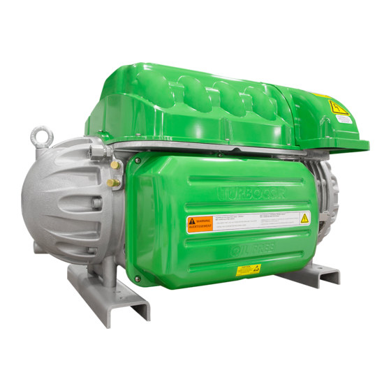
- Page 1 Service Manual - Revision H Danfoss Turbocor® Twin-Turbine Centrifugal Series Compressors TT Series Compressors ® http://turbocor.danfoss.com |...
- Page 2 THIS PAGE INTENTIONALLY LEFT BLANK Page 2 of 294 - M-SV-001-EN Rev. H 1/23/2023...
-
Page 3: Table Of Contents
Table of Contents Table of Contents Chapter 1.0 Introduction 1.1 Application 1.2 Purpose 1.3 Organization 1.4 Commitment to Quality and the Environment 1.5 Safety Summary 1.5.1 Danger Notification 1.5.2 Caution Notification 1.5.3 Note 1.6 Precautions 1.7 Refrigerant Type 1.8 Electrical Isolation 1.9 Handling Static Sensitive Devices 1.9.1 ESD Protection/Grounding 1.10 DC Bus Test Harness Installation and Removal 1.10.1 General Verification and Installation of the DC Bus Test Harness 1.10.2 DC Bus Test Harness Installation for Closed-Top Soft Start 1.10.3 DC Bus Test Harness Installation for Open-Top Soft Starts 1.10.4 General DC Bus Test Harness Removal 1.10.5 DC Bus Test Harness Removal for Closed-Top Soft Starts 1.10.6 DC Bus Test Harness Removal for Open-Top Soft Starts 1.11 Compressor Fasteners 1.12 General O-ring Handling Chapter 2.0 Compressor Fundamentals 2.1 Main Fluid Path 2.2 Motor and Power Electronics Cooling 2.3 Capacity Control 2.4 Compressor Energy and Signal Flow Chapter 3.0 Compressor Removal and Installation 3.1 Refrigerant Containment 3.2 Compressor Removal 3.3 Compressor Installation... - Page 4 Chapter 4.0 Component Identification 4.1 Compressor Covers 4.1.1 Mains Input Cover 4.1.1.1 Mains Input Cover Removal and Installation 4.1.2 Top Cover 4.1.2.1 Top Cover Removal and Installation 4.1.3 Service Side Cover 4.1.3.1 Service Side Cover Removal and Installation 4.1.4 Capacitor Cover 4.1.4.1 Capacitor Cover Removal and Installation 4.1.5 Compressor Cover Torque Specifications 4.2 Cooling Adapter 4.2.1 Cooling Adapter Removal and Installation 4.2.2 Cooling Adapter Torque Specifications 4.3 Compressor Interface Module 4.3.1 Compressor Interface Module Connection Descriptions 4.3.2 Compressor Interface Module Verification 4.3.2.1 Determining if the Compressor Interface Module is Draining Energy 4.3.2.2 Compressor Interface Module Communication Verification 4.3.2.3 Interlock Verification 4.3.3 Compressor Interface Module Removal & Installation 4.3.3.1 Compressor Interface Module Removal 4.3.3.2 Compressor I/O Board Installation 4.4 Compressor Interface Cable 4.4.1 Compressor Interface Cable Verification 4.4.2 Compressor Interface Cable Removal and Installation 4.4.2.1 Compressor Interface Cable Removal 4.4.2.2 Compressor Interface Cable Installation 4.5 Compressor Controller Cable Harness 4.5.1 Compressor Controller Cable Connections 4.5.2 Compressor Controller Cable Harness Removal and Installation 4.5.3 Compressor Controller Cable Harness Torque Specifications 4.6 Solenoids and Coils 4.6.1 Solenoid and Coil Connections 4.6.2 Solenoid Coil Harness 4.6.2.1 Solenoid Coil Harness Removal and Installation 4.6.3 Solenoid Verification 4.6.3.1 Resistance Measurement of Cooling Solenoid Coils 4.6.3.2 Output Voltage to Solenoid Coils 4.6.3.3 Cooling Path Blockage Inspection...
- Page 5 4.6.4 Solenoid and Coil Removal and Installation 4.6.4.1 Solenoid and Coil Removal 4.6.4.2 Solenoid and Actuator Installation 4.6.4.3 Solenoid Torque Specifications 4.7 Interstage Pipe - TTH/TGH 4.7.1 Interstage Pipe Removal and Installation 4.7.1.1 Interstage Pipe Removal 4.7.1.2 Interstage Pipe Installation 4.7.2 Interstage Pipe Torque Specifications 4.8 Compressor Housing End Cap 4.8.1 Compressor Housing End Cap Removal and Installation 4.8.1.1 Compressor Housing End Cap Removal 4.8.1.2 Compressor Housing End Cap Installation 4.8.1.3 Compressor Housing End Cap Torque Specifications 4.9 IGV 4.9.1 IGV Connections 4.9.2 IGV Verification 4.9.2.1 IGV Stepper Motor Verification 4.9.2.2 IGV Operation Verification 4.9.3 IGV Housing Removal and Installation 4.9.3.1 IGV Housing Assembly Removal 4.9.3.2 IGV Assembly Removal 4.9.3.3 IGV Assembly Installation 4.9.4 IGV Torque Specifications 4.10 Mains Plate Bracket 4.10.1 Mains Plate Bracket Removal and Installation 4.10.1.1 Mains Plate Bracket Removal 4.10.1.2 Mains Plate Bracket Installation 4.10.1.3 Mains Plate Torque Specifications 4.11 3-Phase Main Voltage Input Terminal Block 4.11.1 3-Phase Main Voltage Input Terminal Block Verification 4.11.1.1 3-Phase AC input Verification 4.11.1.2 Connecting the AC Input Cable 4.11.1.3 Verifying the 3-Phase AC Input 4.11.2 3-Phase Main Voltage Input Terminal Block Removal and Installation 4.11.2.1 General 3-Phase Main Voltage Input Terminal Block Removal 4.11.2.2 Specific 3-Phase Main Voltage Input Terminal Block Removal - TTS300/TGS230 4.11.2.3 3-Phase Main Voltage Input Terminal Block Removal - TTS/TGS/TTH/TGH (Except TTS300/TGS230) 4.11.2.4 3-Phase Main Voltage Input Terminal Block Installation - TTS300/TGS230 4.11.2.5 3-Phase Main Input Terminal Block Installation - TTH/TGH/TTH/TGH (Except TTS300/TGS230) 4.11.2.6 General 3-Phase Main Voltage Input Terminal Block Installation 4.11.2.7 Terminal Block Torque Specifications...
- Page 6 4.12 Input Mains Bus Bars 4.12.1 Input Mains Bus Bar Removal 4.12.1.1 General Mains Bus Bar Removal 4.12.2 Input Mains Bus Bar Installation 4.12.2.1 General Mains Bus Bar Installation 4.12.3 AC Bus Bar Torque Specifications 4.13 Terminal Block Fuse Replacement 4.13.1 Verification of Terminal Block Fuse 4.13.2 Terminal Block Fuse Removal and Installation 4.13.2.1 Terminal Block Fuse Removal 4.13.2.2 Terminal Block Fuse Installation 4.14 Soft Start 4.14.1 Soft Start Connections 4.14.2 Soft Start Verification 4.14.2.1 Verifying Soft Start Voltages 4.14.2.2 Verifying Soft Start Fuses 4.14.3 Soft Start Removal and Installation 4.14.4 Soft Start Removal (Closed-Top) 4.14.5 Soft Start Removal (Open-Top) 4.14.6 Soft Start Installation (Closed-Top) 4.14.7 Soft Start Installation (Open-Top) 4.14.8 Soft Start Fan Removal and Installation 4.14.9 Soft Start Fan Removal 4.14.10 Soft Start Fan Installation 4.14.10.1 Soft Start Torque Specifications 4.15 SCR DC Bus Bar - TTS300/TGS230 4.15.1 SCR DC Bus Bar Removal and Installation 4.15.1.1 SCR DC Bus Bar Removal - TTS300/TGS230 4.15.1.2 SCR DC Bus Bar Installation - TTS300/TGS230 4.15.1.3 SCR DC Bus Bar Torque Specifications 4.16 Soft Start SCR Gate Cable 4.16.1 Soft Start SCR Gate Cable Connections 4.16.2 Soft Start SCR Gate Cable Removal and Installation 4.16.2.1 Soft Start SCR Gate Cable Removal 4.16.2.2 Soft Start SCR Gate Cable Installation 4.17 Soft Start AC/DC Harness 4.17.1 Soft Start AC/DC Harness Connections 4.17.2 Soft Start AC/DC Harness Removal and Installation 4.17.2.1 Soft Start AC/DC Harness Removal - TTS300/TGS230 4.17.2.2 Soft Start AC/DC Harness Removal - TTS/TGS/TTH/TGH (Except TTS300/TGS230) Page 6 of 294 - M-SV-001-EN Rev.
- Page 7 4.17.2.3 Soft Start AC/DC Harness Installation - TTS300/TGS230 4.17.2.4 Soft Start AC/DC Harness Installation - TTS/TGS/TTH/TGH (Except TTS300/TGS230) 4.17.2.5 Soft Start AC/DC Harness Torque Specifications 4.18 Silicone-Controlled Rectifier 4.18.1 SCR Connections 4.18.2 SCR Verification 4.18.2.1 Diodes Verification - Two-Hole Mount 4.18.2.2 Diodes Verification - Four-Hole Mount 4.18.2.3 Gates Verification 4.18.2.4 SCR Temperature Sensor 4.18.2.5 SCR Temperature Sensor Verification 4.18.2.6 SCR Temperature Sensor General Removal 4.18.2.7 SCR Temperature Sensor Removal - TTS300/TGS230 4.18.2.8 SCR Temperature Sensor Removal - TTS/TGS/TTH/TGH Rev. F and Earlier (Except TTS300/TGS230) 146 4.18.2.9 SCR Temperature Sensor Installation - TTS300/TGS230 4.18.2.10 SCR Temperature Sensor Installation - TTS/TGS/TTH/TGH Rev. F and Earlier (Except TTS300/TGS230) 4.18.2.11 SCR Temperature Sensor General Installation 4.18.2.12 SCR Temperature Sensor Torque Specifications 4.18.3 SCR Removal and Installation 4.18.3.1 SCR General Removal 4.18.3.2 SCR Removal - T TS300/TGS230 4.18.3.3 SCR Removal - TTS/TGS/TTH/TGH (Except TTS300/TGS230) 4.18.3.4 SCR Installation - TTS300/TGS230 4.18.3.5 SCR Installation - TTS/TGS/TTH/TGH (Except TTS300/TGS230) 4.18.3.6 SCR General Installation 4.18.3.7 SCR Torque Specifications 4.19 SCR Cooling Manifold 4.19.1 SCR Cooling Manifold General Removal Steps 4.19.2 SCR Cooling Manifold Specific Removal Steps - TTS300/TGS230 4.19.3 SCR Cooling Manifold Specific Removal Steps - TTS/TGS/TTH/TGH (Except TTS300/TGS230) 4.19.4 SCR Cooling Manifold Specific Installation Steps - TTS300/TGS230 4.19.5 SCR Cooling Manifold Specific Installation Steps - TTS/TGS/TTH/TGH (Except TTS300/TGS230) 4.19.6 SCR Cooling Manifold General Installation Steps 4.19.7 SCR Cooling Manifold Torque Specifications 4.20 Snubber Capacitors 4.21 DC Capacitor Bus Bar Assembly 4.21.1 DC Capacitor DC Bus Bar Connections 4.21.2 DC Bus Voltage Verification 4.21.2.1 Bleed Resistor Verification...
- Page 8 4.21.4.1 DC Capacitor Bus Bar Assembly Removal - TTS300/TGS230 4.21.4.2 DC Capacitor Bus Bar Assembly Removal - TTS/TGS/TTH/TGH (Except TTS300/TGS230) 4.21.4.3 DC Capacitor Bus Bar Assembly Installation - TTS300/TGS230 4.21.4.4 DC Capacitor Bus Bar Assembly Installation - TTS/TGS/TTH/TGH (Except TTS300/TGS230) 4.21.5 DC Capacitor Bus Bar Assembly General Installation Steps 4.21.6 DC Capacitor Bus Bar Assembly Torque Specifications 4.22 Inverter 4.22.1 Inverter Connections 4.22.2 Inverter Verification 4.22.3 Inverter Cable Harness 4.22.4 Inverter Cable Harness Removal and Installation 4.22.4.1 Inverter Cable Harness Removal 4.22.4.2 Inverter Cable Harness Installation 4.22.5 Inverter Cable Harness Torque Specifications 4.22.6 Inverter Removal and Installation 4.22.6.1 Compressor Specific Inverter Removal Steps - TTS300/TGS230 4.22.6.2 Compressor Specific Inverter Removal Steps - TTS/TGS/TTH/TGH (Except TTS300/TGS230) 4.22.6.3 Compressor Specific Inverter Installation Steps - TTS300/TGS230 4.22.6.4 Compressor Specific Inverter Installation Steps - TTS/TGS/TTH/TGH (Except TTS300/TGS230) 4.22.7 Inverter Card Replacement 4.22.7.1 Inverter Card Removal 4.22.7.2 Inverter Control Card Installation 4.22.8 Inverter Torque Specifications 4.23 Motor Components 4.23.1 Function 4.23.1.1 Stator 4.23.1.2 Rotor 4.23.2 Motor Protection 4.23.3 Motor Connections 4.23.4 Motor Verification 4.23.4.1 Stator Insulation Verification 4.23.4.2 Stator Resistance Verification 4.23.4.3 Stator Thermistor Resistance Verification 4.23.5 Motor Components Removal and Installation 4.23.5.1 Motor Bus Bar Removal 4.23.5.2 Motor Bus Bar Installation 4.23.5.3 Copper Tube Removal 4.23.5.4 Copper Tube Installation 4.23.5.5 Motor Cover Plate Removal 4.23.5.6 Motor Cover Plate Installation 4.23.5.7 High Power Feedthrough Removal 4.23.5.8 High-Power Feedthrough Installation 4.23.5.9 Motor Assembly Torque Specifications...
- Page 9 4.24 High Voltage DC-DC Converter 4.24.1 DC-DC Converter Function 4.24.2 DC-DC Converter Verification 4.24.2.1 Input Voltage Verification 4.24.2.2 Output Voltage Verification 4.24.2.3 Input Resistance Measurement 4.24.2.4 Output Resistance Measurement 4.24.3 DC-DC Removal and Installation 4.24.3.1 DC-DC Torque Specifications 4.24.4 DC-DC Supply Cable Harness 4.24.5 DC-DC Harness Removal and Installation 4.24.5.1 DC-DC Harness Removal 4.24.5.2 DC-DC Harness Installation 4.25 Backplane 4.25.1 Backplane Function 4.25.2 Backplane Connections and Test Points 4.25.2.1 LED Locations 4.25.2.2 Backplane Verification 4.25.3 Backplane Removal and Installation 4.25.3.1 Backplane Removal 4.25.3.2 Backplane Installation 4.25.3.3 Backplane Torque Specifications 4.26 Serial Driver 4.26.1 Serial Driver Function 4.26.2 Serial Driver Connections 4.26.3 Serial Driver Verification 4.26.3.1 Serial Driver Input Voltage 4.26.3.2 Serial Driver Output Voltage Verification 4.26.4 Serial Driver Removal and Installation 4.26.4.1 Serial Driver Removal 4.26.4.2 Serial Driver Installation 4.27 BMCC 4.27.1 BMCC Connections 4.27.2 BMCC Verification 4.27.2.1 BMCC Power Verification 4.27.2.2 BMCC Communication Verification 4.27.3 BMCC Battery and Verification 4.27.3.1 BMCC Battery Safety 4.27.3.2 BMCC Battery Verification 4.27.4 BMCC Removal and Installation 4.27.4.1 BMCC Removal 4.27.4.2 BMCC Installation M-SV-001-EN Rev.
- Page 10 4.28 Bearing Pulse Width Modulator Amplifier 4.28.1 PWM Function 4.28.2 PWM Connections 4.28.3 PWM Verification 4.28.3.1 Verify if the Bearing PWM Amplifier is Draining Energy 4.28.3.2 Verify Functionality of the Five Output Channels 4.28.3.3 Verify Functionality of the Five Diode Sets 4.28.4 PWM Removal and Installation 4.28.4.1 PWM Amplifier Removal 4.28.4.2 PWM Amplifier Installation 4.28.4.3 PWM Torque Specifications 4.29 Magnetic Bearings 4.29.1 Magnetic Bearings Function 4.29.2 Magnetic Bearings Connections 4.29.3 Bearing Verification 4.29.3.1 Bearing Coil Verification 4.29.3.2 Bearing Current Verification 4.29.4 Bearing Power Feedthrough Removal and Installation 4.29.4.1 Bearing Power Feedthrough Removal 4.29.4.2 Bearing Power Feedthrough Installation 4.29.4.3 Magnetic Bearing Torque Specifications 4.30 Bearing Sensors 4.30.1 Bearing Sensor Function 4.30.2 Bearing Sensor Connection 4.30.3 Bearing Sensor Verification 4.30.3.1 Bearing Sensor Resistance Verification 4.30.3.2 Bearing Sensor Cable Verification 4.30.4 Bearing Sensor Cable Removal and Installation 4.30.5 Bearing Sensor Feedthrough Removal and Installation 4.30.5.1 Bearing Sensor Feedthrough Removal 4.30.5.2 Bearing Sensor Feedthrough Installation 4.30.5.3 Bearing Sensor Torque Specifications 4.31 Cavity Temperature Sensor 4.31.1 Cavity Temperature Sensor Function 4.31.2 Cavity Temperature Sensor Connections 4.31.3 Cavity Temperature Sensor Verification 4.31.4 Cavity Temperature Sensor Removal and Installation 4.31.4.1 Cavity Temperature Sensor Removal 4.31.4.2 Cavity Temperature Sensor Installation 4.31.4.3 Cavity Sensor Torque Specifications 4.32 Pressure/Temperature Sensor Page 10 of 294 - M-SV-001-EN Rev.
- Page 11 4.32.1 Pressure/Temperature Sensor Function 4.32.2 Pressure/Temperature Sensor Connections 4.32.3 Pressure/Temperature Sensor Verification 4.32.4 Pressure/Temperature Sensor Removal and Installation 4.32.4.1 Suction Pressure/Temperature Sensor Removal 4.32.4.2 Suction Pressure/Temperature Sensor Installation 4.32.4.3 Discharge Pressure/Temperature Sensor Removal 4.32.4.4 Discharge Pressure/Temperature Sensor Installation 4.32.4.5 Interstage Pressure/Temperature Sensor Removal (TTH/TGH Compressors Only) 4.32.4.6 Interstage Pressure/Temperature Sensor Installation (TTH/TGH Compressors Only) 4.32.4.7 Pressure/Temperature Sensor Torque Specifications Chapter 5.0 lTroubleshooting 5.1 Alarm and Fault Indications 5.1.1 Alarm Types 5.1.2 Fault Types 5.2 Troubleshooting with the Service Monitoring Tools Software 5.2.1 Compressor Fault Troubleshooting 5.2.2 Motor/System Faults Troubleshooting 5.2.3 Bearing Fault Troubleshooting 5.3 Bearing Calibration 5.3.1 When to Calibrate the Bearings 5.3.1.1 Calibration when Commissioning 5.3.1.2 Regular Maintenance Calibration 5.3.1.3 Calibration when Troubleshooting 5.3.1.4 BMCC Change 5.3.2 Performing a Calibration 5.3.2.1 Before Performing a Calibration 5.3.2.2 Calibration 5.3.3 After Calibration is Complete 5.3.3.1 Validate 5.3.3.2 Save to EEPROM 5.3.4 Create a Calibration Report 5.3.5 Calibration Report Analysis 5.4 SMT Compressor Connection Status Indications 5.5 System and Compressor Level Troubleshooting 5.5.1 Compressor Voltage Troubleshooting 5.5.2 Determining the Cause of an Energy Drain 5.5.2.1 Determining if Serial Driver is Draining Energy 5.5.2.2 Determining if BMCC is Draining Energy 5.5.2.3 Determine if PWM is Draining Energy 5.5.2.4 Determining if Inverter is Draining Energy...
- Page 12 5.5.2.5 Determining if Compressor I/O Board is Draining Energy 5.5.2.6 Determining the Cause of Blown Soft Start Fuses (Closed-Top Soft Start Only) 5.5.3 Troubleshooting an Open Interlock 5.5.4 Troubleshooting the Inverter Chapter 6.0 Maintenance 6.1 Preventative Maintenance Tasks 6.2 Moisture Prevention Measures 6.2.1 Required Items 6.2.1.1 Service Side Disassembly 6.2.1.2 Service Side Assembly 6.2.1.3 Top Side Appendix A Acronyms/Terms Appendix B Compressor Troubleshooting Flowcharts Appendix C Compressor Test Sheet Page 12 of 294 - M-SV-001-EN Rev. H 1/23/2023...
- Page 13 List of Changes Revision Date Page Description of Change 05-30-2019 Redevelopment of manual to include TTH/TGH and support Revision F and later compressors 06-10-2019 15/16 Updated Typecode figures 1-1 and 1-2. 11-10-2019 18-19, & 28 Updated TGS490 compressor with R515B refrigerant. 11-10-2019 Removed helium and changed the inert gas pressure to 15 psi. 11-10-2019 Updated F4 and F5 fuse description. 05-27-2020 Manual updated to include all Major Revision H changes. 12-23-2022 Manual edited and improved for content and completeness M-SV-001-EN Rev. H-1/23/2023 Page 13 of 294...
- Page 14 THIS PAGE INTENTIONALLY LEFT BLANK Page 14 of 294 - M-SV-001-EN Rev. H 1/23/2023...
- Page 15 Danfoss LLC reserves the right to revise the publication at any time and to make changes to its contents without prior notice or any obligation to notify former or present users of such revisions or changes. Danfoss Turbocor Compressors Inc. 1769 East Paul Dirac Drive Tallahassee, Florida 32310 Phone 1-850-504-4800 Fax 1-850-575-2126 http://turbocor.danfoss.com Encounter an error or see an opportunity for improvements while reading this manual? Email us at turbocor.contact@danfoss.com with a brief description. * Subject to change without notice. * Danfoss Turbocor’s commitment to excellence ensures continuous product improvements. M-SV-001-EN Rev. H-1/23/2023 Page 15 of 294...
- Page 16 THIS PAGE INTENTIONALLY LEFT BLANK Page 16 of 294 - M-SV-001-EN Rev. H 1/23/2023...
-
Page 17: Chapter 1.0 Introduction
Chapter 1.0 Introduction This section provides a brief introduction to the Service Manual including the Application, Purpose, Organization, Document Conventions used, Safety Information, and the Danfoss LLC Quality Policy. 1.1 Application As of May 6, 2019, the product nomenclature changed. Figure 1-1 O ld to New Type Code maps the old structure of the Type code to the new structure. Additionally, the “Series” indicators have an additional character in order to differentiate the standard compressors from high-lift compressors. Unless the compressor is a high-lift design, an “S” will be added (e.g., TTS350). A high lift compressor will have an “H” in the Series designation (e.g., TTH375). Throughout this manual, it shall be assumed that if a series designation contains neither an "S" or "H" (e.g., TT350) that it is not a high-lift design. Refer to Figure 1-2 N ew Type Code for a complete description in the new design. Figure 1-1 Old to New Type Code M-SV-001-EN Rev. H-1/23/2023 Page 17 of 294... - Page 18 Figure 1-2 New Type Code Page 18 of 294 - M-SV-001-EN Rev. H 1/23/2023...
-
Page 19: Purpose
1.2 Purpose This Service Manual is intended to provide service procedures specific to the Danfoss Turbocor compressors. It is not intended to teach basic fundamental safety, refrigeration, electrical, or fitting skills. It is assumed persons using this manual will be appropriately certified and have detailed knowledge, experience, and skills in respect to working with high-pressure refrigerants and medium voltage electrical components to 1 Kilovolt (kV) high-power alternating current (AC) and direct current (DC). Some potential safety situations may not be foreseen or covered in this manual. Danfoss LLC expects personnel using this manual and working on Danfoss Turbocor compressors to be familiar with, and carry out, all safe work practices necessary to ensure safety for personnel and equipment. The purpose of this manual is to provide: A general description of the compressor design A functional description of the various components of the compressor Information regarding procedures necessary to detect the source of a problem within the compressor The procedures for disassembling and assembling various components of the compressor Fault and calibration interpretations System troubleshooting suggestions NOTE Bearing and bearing sensor repairs are not covered in this manual as they are not field serviceable. Compressors requiring such repairs must be sent back to the factory for inspection and repair. This manual gives only general procedures for servicing and does not provide part numbers of single products or single components. If this information is required, please contact a recognized Danfoss Turbocor original equipment manufacturer (OEM) customer. Additionally, this manual is written for Major revision F and later compressors. When necessary, particular revision compressors are specified, but the majority of the content remains the same, regardless of the compressor revision. Danfoss LLC does sell various upgrade kits (e.g., Soft Start Upgrade Kit) and those kits may include retrofit cabling or other hardware that are not specifically installed on production compressors. This manual only illustrates components that were installed on production compressors. Always refer to the specific spare part kit instructions during installation. 1.3 Organization This manual is organized in the following manner: ... -
Page 20: Commitment To Quality And The Environment
Monitoring Program Window Names – all window names will be in italic. Example Compressor Controller window. Internal References – references to sections within this manual are encapsulated in quotes. Example, Isolate the compressor power as described in the “Electrical Isolation of the Compressor" section of this manual. External References – references to items not within this manual are underlined. Example; Refer to the TTS/TGS/TTH/TGH Applications Manual for installation procedures. 1.4 Commitment to Quality and the Environment Danfoss Turbocor Compressors (DTC) is dedicated to leading through innovation and to satisfying our customers with the best quality, value, and on-time delivery of high-efficiency oil-free centrifugal compressors. We are committed to controlling our impact on the environment demonstrated through setting goals focused on continual improvement and complying with all relevant legislation, regulation, and other requirements to protect the environment. 1.5 Safety Summary Safety precautions must be observed during installation, start-up, and service of the compressor due to the presence of pressure and voltage hazards. Only qualified and trained personnel should install, start up, and service Danfoss Turbocor compressors. Safety information is located throughout the manual to alert service personnel of potential hazards and is identified by the headings DANGER and CAUTION. 1.5.1 Danger Notification A DANGER notification signifies an essential operation or maintenance procedure, practice, or condition which, if not strictly observed, could result in injury to or death of personnel or long-term health hazards. A Danger notification is displayed in the format shown in Figure 1-3 D anger Notification Example. -
Page 21: Caution Notification
1.5.2 Caution Notification A CAUTION notification signifies an essential operation or maintenance procedure, practice, or condition which, if not strictly observed, could result in damage to or destruction of equipment or potential problems in the outcome of the procedure being performed. A Caution notification is displayed in the format shown in Figure 1-4 C aution Notification Example. Figure 1-4 Caution Notification Example • • • CAUTION • • • 1.5.3 Note A NOTE provides additional information such as a tip, comment, or other useful, but not imperative information. A Note is displayed in the format shown in Figure 1-5 N ote Example. Figure 1-5 Note Example NOTE 1.6 Precautions Consideration for personal safety and equipment safety is very important. This chapter contains various sections that cover safety precautions and methods that must be followed when servicing the compressor. Prior to servicing ... -
Page 22: Electrical Isolation
1.8 Electrical Isolation Before servicing the Compressor, isolate the compressor power by completing the following steps: • • • DANGER! • • • This equipment contains hazardous voltages that can cause serious injury or death. Only qualified and trained personnel should work on Danfoss LLC equipment. Always wear appropriately-rated safety equipment when working around equipment and/or components energized with high voltage. Removing the Mains Input Cover will expose the technician to a high voltage hazard of up to 632 VAC. Ensure the Mains Input power is turned off and locked out before removing the Mains Input Cover. 1. Turn off the Mains Input power to the compressor. 2. Lock Out/Tag Out (LOTO) the mains disconnect to ensure no accidental or unauthorized reapplication of the Mains Input power can occur. NOTE The Mains Input fast-acting fuses are installed in the power panel for all compressor models except the TTS300/TGS230. 3. Remove the Mains Cover only. Refer to Section 4.1.1 M ains Input Cover on page 52. 4. Using an appropriately-rated voltage meter, confirm the absence of AC voltage. • • • DANGER! • • •... - Page 23 Figure 1-6 DC Bus Voltage Test Points NOTE Refer to the applicable service procedure as that may require the covers to remain off. M-SV-001-EN Rev. H-1/23/2023 Page 23 of 294...
-
Page 24: Handling Static Sensitive Devices
1.9 Handling Static Sensitive Devices Figure 1-7 ESD Susceptible Caution Label Active electronic components are susceptible to damage when exposed to static electrical charges. Damage to such components may lead to outright failure or reduction in service life. Since the presence of static charges is not always evident, it is essential that service personnel follow static control procedures at all times when handling sensitive electronic components. This section outlines static control precautions that must be followed when providing service support in the field. Service support personnel should create a safe, static-free environment. Service personnel must use a commercially available service kit for handling static-sensitive devices. The kit typically includes: Ground cord assembly Alligator clip Grounding wrist strap Wrist strap tester If a safe, static control environment cannot be created for a specific reason, the operator will ensure that electrostatic discharge (ESD) items and personnel are at the same electrical potential as the equipment. The electronic modules should only be removed from the ESD protective bag at the last moment, just before installation when the operator is ready to do the replacement. The operator should avoid touching any components or connectors on the module and should hold the module by its edge or enclosure, as applicable. 1.9.1 ESD Protection/Grounding All parts that are susceptible to damage by ESD will be marked using the following label. Refer to Figure 1-8 E SD Label. Please follow the instructions below to ensure safety and to protect the parts from ESD damage. -
Page 25: Dc Bus Test Harness Installation And Removal
Figure 1-9 Mains Plate and Ground Post 3. If you need to remove the Soft Start, clip the ESD strap ground clip to the mains plate. Refer to Figure 1-9 M ains Plate and Ground Post. 4. If you only need to remove the Service Side Cover, clip the ESD strap ground clip to the cover screw hole that is part of the compressor housing. Refer to Figure 1-10 C ompressor Grounding Points on page 25. 5. Install the top covers. Refer to Section 4.1 C ompressor Covers on page 52. Figure 1-10 Compressor Grounding Points 1.10 DC Bus Test Harness Installation and Removal A DC bus test harness must be used when testing the voltages of the compressor’s power electronics. The DC bus test harness is not designed to be left in the compressor during normal operation. When checks are complete, disconnect and remove the test harness. There are two (2) different Soft Start versions referenced within these instructions. The steps below are organized based on which Soft Start is installed on the compressor. To identify the installed Soft Start, refer to Section 4.14 S oft Start on page 113. M-SV-001-EN Rev. -
Page 26: General Verification And Installation Of The Dc Bus Test Harness
All versions of the DC Bus Test Harness have male/female plugs to allow piggyback connection to the required voltage measurement points on the Soft-Start. Refer to Figure 1-11 D C Bus Test Harness Diagram (Closed-Top Soft Start) and Figure 1-12 D C Bus Test Harness Diagram (Open-Top Soft Start) on page 26. for an example of the two current harnesses. Voltage measurements are made via shrouded multimeter jacks on the opposite end of the cables. Cable and personal protection are provided by inline fast-acting fuses (1/4 x 1 1/4, 62 milliamp 250V) and current-limiting 100kΩ 3W resistors. Figure 1-11 DC Bus Test Harness Diagram (Closed-Top Soft Start) Figure 1-12 DC Bus Test Harness Diagram (Open-Top Soft Start) • • • CAUTION • • • Before using the DC bus test harness, integrity of the fuses/resistors in the harness and cable must be checked. 1.10.1 General Verification and Installation of the DC Bus Test Harness 1. ... -
Page 27: Dc Bus Test Harness Installation For Closed-Top Soft Start
NOTE This would be a good time to perform a visual inspection of the top-side electronics to determine if there is any visual damage present. Also at this time, it is suggested to verify the integrity of the fuses if you have a Closed-Top Soft Start. 4. Confirm the integrity of the fuses and resistors in the DC bus test harness by using a multimeter set to resistance. Check each cable individually. Refer to Figure 1-11 D C Bus Test Harness Diagram (Closed- Top Soft Start) on page 26 and Figure 1-12 D C Bus Test Harness Diagram (Open-Top Soft Start) on page 26 for harness fuse and resistor locations. The reading for the resistor should be approximately 100kΩ and the reading for the fuse should be 29Ω. 5. Continue to the appropriate section below based on the particular Soft Start. 1.10.2 DC Bus Test Harness Installation for Closed-Top Soft Start 1. Disconnect the J1 and J7 connectors on the Soft Start Board. Refer to Figure 1-13 S oft Start (Closed Top). Figure 1-13 Soft Start (Closed Top) 2. Connect the two (2) plugs of the compressor cable harness into the corresponding sockets of the DC bus test harness. Refer to Figure 1-14 ... - Page 28 Figure 1-15 DC Bus Test Harness Connection Diagram (Closed-Top Soft Start) 3. Connect the two (2) plugs of the DC bus test harness into the Soft Start. Refer to Figure 1-13 S oft Start (Closed Top) on page 27. 4. Route the cables through the cable passage on either side of the DC-DC Converter, down into the service side. Refer to Figure 1-16 C able Passage. NOTE For clarity purposes, several components have been removed from Figure 1-16 C able Passage Figure 1-16 Cable Passage 5. Carefully adjust the connectors and harness so that the Top Cover can be reinstalled. 6. Install the top covers. Refer to Section 4.1 C ompressor Covers on page 52. 7. Remove ESD strap from the compressor and yourself. 8. ...
- Page 29 9. Using an appropriately-rated voltmeter with the 1000VDC range selected, insert the positive voltmeter lead into the DC (+F) test harness lead, and the negative voltmeter lead into the DC (-) test harness lead. If the voltage corresponds toTable 1-2 E xpected DC Bus Voltage, the DC bus voltage is correct and HV DC (F1) fuse on the Soft Start is intact. This would imply that the Soft Start and Silicon-Controlled Rectifiers (SCRs) are functioning correctly; proceed to Step 12. If voltage reads 0, go to Step 10. Table 1-2 Expected DC Bus Voltage Compressor Nameplate AC Voltage Acceptable AC Voltage Range Expected DC Bus Voltage Range 575 VAC 518-632 VAC 700-853 VDC 460 VAC 414-506 VAC 559-683 VDC 400 VAC 360-440 VAC 486-594 VDC 380 VAC 342-418 VAC 462-564 VDC 10. ...
-
Page 30: Dc Bus Test Harness Installation For Open-Top Soft Starts
1.10.3 DC Bus Test Harness Installation for Open-Top Soft Starts 1. Disconnect the J8 connector from the Soft Start. Refer to Figure 1-17 J 8 Soft Start Connection (Open Top). Figure 1-17 J8 Soft Start Connection (Open Top) 2. Connect the plug of the compressor cable harness into the corresponding socket of the DC bus test harness. Refer to Figure 1-18 C onnect DC Bus Test Harness (Open-Top Soft Start) and Figure 1-19 D C Bus Test Harness Connection Diagram (Open-Top Soft Start) for this and the following step. 3. Connect the plug of the DC bus test harness into the Soft Start. Figure 1-18 Connect DC Bus Test Harness (Open-Top Soft Start) Figure 1-19 DC Bus Test Harness Connection Diagram (Open-Top Soft Start) Page 30 of 294 - M-SV-001-EN Rev. -
Page 31: General Dc Bus Test Harness Removal
4. Route the cables through the cable passage beside the DC-DC Converter, down into the service side. Refer to Figure 1-16 C able Passage on page 28. NOTE When checks are complete, disconnect and remove the test harness. 5. Reinstall the Top Cover and Mains Input Cover. Refer to 4.1 C ompressor Covers on page 52. 6. Reapply AC power to the Compressor. 7. Insert the positive voltmeter lead into the DC (+) test harness lead, and the negative voltmeter lead into the DC (-) test harness lead. Refer to Table 1-2 E xpected DC Bus Voltage on page 29 for the expected DC bus voltage. If the DC bus voltage is not present, or if it is outside the “Expected DC Bus Voltage” range shown in Table 1-2 E xpected DC Bus Voltage on page 29, verify proper incoming AC input, verify SCR Gates, and verify SCR Diodes. If incoming AC power is correct, and the SCRs pass the diode and gate tests, replace the Soft Start. NOTE There are no replaceable fuses present in the Open-Top Soft Start. 8. When finished, remove the DC Bus Test Harness. Refer to Section 1.10.4 G eneral DC Bus Test Harness Removal. 1.10.4 General DC Bus Test Harness Removal 1. ... -
Page 32: Compressor Fasteners
6. Install all covers on the compressor. Refer to Section 4.1 C ompressor Covers on page 52. 7. Return the compressor to normal operation. 1.11 Compressor Fasteners • • • CAUTION • • • Only replace fasteners with exact replacements. Failure to do so could lead to fastener corrosion and/or failure. 1.12 General O-ring Handling Various O-rings are utilized throughout the TTSeries Compressors to contain the refrigerant. Prior to the removal of any component utilizing an O-ring, the refrigerant must be properly recovered per industry-standard procedures. Upon O-ring replacement, a leak test should be performed. The following O-ring-specific steps are required when replacing any compressor O-ring: 1. Remove each O-ring to be installed from its package and inspect for defects such as blemishes, abrasions, cuts, or punctures. 2. Slight stretching of the O-ring when it is rolled inside out will help to reveal some defects not otherwise visible. 3. After inspection and prior to installation, lubricate the O-ring with a light coat of Super-O-Lube. 4. Avoid rolling or twisting the O-ring when maneuvering it into place. 5. Keep the position of the O-ring mold line constant. ... -
Page 33: Chapter 2.0 Compressor Fundamentals
Chapter 2.0 Compressor Fundamentals Compressor operation begins with a demand signal applied to the compressor. The startup sequence is configurable in the startup settings. See the OEM Programming Manual for further details. 2.1 Main Fluid Path The compressor is a two-stage centrifugal type compressor utilizing variable speed as the principle means of capacity control with inlet guide vanes (IGVs) assisting when required. Refrigerant enters the first stage suction side of the compressor as a low-pressure, low-temperature, superheated vapor. It then passes through variable IGVs that assist compressor control at part-load conditions. Both impellers are mounted on a common shaft. Vapor passes through the first-stage impeller where velocity energy is added to the refrigerant. This is converted to an intermediate pressure in the first-stage volute. Vapor then enters the second-stage impeller through a diffuser. In the second stage, impeller velocity energy is again added to the refrigerant and converted to the final discharge pressure in the discharge diffuser and volute. From the second-stage impeller, refrigerant passes as a high pressure, superheated vapor to the system discharge line. Figure 2-1 Compressor Fluid Paths Table 2-1 Compressor Fluid Paths Component Component Low Pressure/Low Temperature Gas High-Pressure/High Temperature Gas Inlet Guide Vanes (IGVs) Second-Stage Impeller First-Stage Impeller Vaned Diffuser Volute Assembly Vaneless Diffuser Discharge Port De-Swirl Vanes ... - Page 34 Figure 2-2 Cooling Inlet Adapter Liquid refrigerant is internally channeled to two (2) solenoid valves. These valves have integral orifices that act as expansion devices to cool the compressor motor, shaft (rotor) and power electronics. TTS300 and TGS230 compressors have these solenoids arranged so that all components are cooled in series with each other and the solenoids act as two (2) stages of cooling capacity. The TTS350, TTS400, TTS450, TTS500, TTS700, TTH375, TGS310, TGS380, TGS390, TGS490, TGS520, a nd TGH285 compressors have separate cooling paths for motor and power electronics. These cooling methods are identified as serial or split cooling. Serial cooling has its return point to the inlet of the first-stage impeller, thus cooling all components with refrigerant evaporating at the saturated suction temperature. In serial cooling versions, Solenoid One (1) is opened if any temperature reaches its “turn on” point and Solenoid Two (2) is opened if any temperature reaches a second “turn on” point value. Refer to Figure 2-5 C ompressor Cooling Path - TTS300/TGS230 on page 37. The split cooling has the motor/shaft cooling circuit return to the first-stage impeller inlet and the power electronics return to the second-stage impeller inlet. This ensures a higher evaporating (cooling) temperature to minimize condensation around the power electronic components. In the split cooling version, Solenoid One (1) is opened if either the cavity temperature or the motor temperature reaches its “turn on” point and Solenoid Two (2) is opened if the Inverter or SCR temperature reaches its “turn on” point. Refer to Figure 2-4 S plit Cooling Path - (TTS/TGS (Except TTS300/TGS230 Serial Cooling)) on page 36. Medium temperature (MT) version compressors require their motor cooling suction line to be vented externally to the main suction line through an evaporator pressure regulating (EPR) valve. This valve is required to ensure that evaporating temperatures cooling the motor and electronics do not get too cold. The EPR valve should be adjusted to maintain a minimum evaporation temperature of 0.8°C (34°F). Refer to the TTS/TGS/TTH/TGH Applications Manual for further details. Serial Cooling compressors can be identified by having only one 1/4 inch flare Schrader connection adjacent to the main motor cooling liquid connection, while a split cooling model will have two (2). These 1/4 inch flare connections access the refrigerant feeds to the components being cooled and bypass the solenoid valves. A minimum pressure ratio of 1.5 and a full liquid seal at the compressor is required to ensure proper and correct compressor cooling. Page 34 of 294 - M-SV-001-EN Rev. H 1/23/2023...
- Page 35 Figure 2-3 Split Cooling Path - TTH375/TGH285 Description Description Solenoid M Radial Bearing Liquid Refrigerant Inlet Axial Bearing Solenoid E Impeller - 1st Stage Inverter Motor Cavity Temp. Sensor BMCC Impeller - 2nd Stage Inverter Temp Sensor Radial Bearing PRV (pressure regulating valve) Stator/Rotor M-SV-001-EN Rev. H-1/23/2023 Page 35 of 294...
- Page 36 Figure 2-4 Split Cooling Path - (TTS/TGS (Except TTS300/TGS230 Serial Cooling)) Table 2-2 Split Cooling Path - (TTS/TGS (Except TTS300/TGS230 Serial Cooling) Description Description From Motor Winding Temp Sensor SCR Manifold BMCC Motor/Rotor Cooling Gas Solenoid M From Motor Cavity Temp. Sensor Solenoid E E Schrader Valve Liquid Refrigerant Inlet M Schrader Valve Orifices Inverter Inverter Temp Sensor High SST Option ...
-
Page 37: Capacity Control
Figure 2-5 Compressor Cooling Path - TTS300/TGS230 Table 2-3 Compressor Cooling Path - (TTS300/TGS230) Description Description From Motor Winding Temp Sensor SCR Manifold BMCC Motor/Rotor Cooling Gas Solenoid M 10 *MT Only Cooling path re-enters at the suction line of the chiller Solenoid E 11 *MT Only Pressure Regulating Valve Liquid Refrigerant Inlet 12 *MT Only Cooling path redirects outside of the compressor Orifice From Motor Cavity Temp. Sensor From Inverter Temp Sensor Inverter 2.3 Capacity Control Capacity control of the compressor is achieved primarily by speed modulation. When unloading, the compressor’s first action is to reduce speed to slightly above the minimum (surge) speed for the pressure ratio present at the time. Further reduction in capacity and an increase in shaft/impeller stability can be achieved by closing the IGVs. These ... -
Page 38: Compressor Energy And Signal Flow
Speed modulation is achieved by the use of “Inverter” control. To accomplish this, the incoming 3-phase AC supply is converted to high voltage DC, incorporating smoothing/storage capacitors, and then switched by the Inverter, utilizing 3-phase rectifiers, to give a simulated 3-phase AC supply of variable voltage and frequency to the compressor motor. 2.4 Compressor Energy and Signal Flow During normal operation, 3-phase power is required to be connected to the compressor at all times, even if it is not running. Power is distributed through the following components to maintain compressor operation: Silicon-Controlled Rectifier (SCR) Soft Start Board DC Capacitor Bus Bar Assembly Inverter Stator High-Voltage (HV) DC-DC Converter Backplane Bearing Motor Compressor Controller (BMCC) Serial Driver Bearing Pulse Width Modulation (PWM) Amplifier Compressor I/O Board Solenoid actuators The order of power and signal flow through the compressor components is as follows. Refer to Figure 2-6 Compressor Energy and Signal Flow Connections on page 39: 1. A 3-phase voltage source is provided to the compressor through the voltage input terminal. 2. ... - Page 39 Figure 2-6 Compressor Energy and Signal Flow Connections M-SV-001-EN Rev. H-1/23/2023 Page 39 of 294...
- Page 40 Refer to Figure 2-7 C ompressor Energy and Control Flow Block Diagram - TT Series Compressors for a block diagram summary of the energy and voltage signal flow through the compressor. NOTE TTH/TGH Compressors are very similar to Figure 2-7 C ompressor Energy and Control Flow Block Diagram - TT Series Compressors. Figure 2-7 Compressor Energy and Control Flow Block Diagram - TT Series Compressors Page 40 of 294 - M-SV-001-EN Rev. H 1/23/2023...
-
Page 41: Chapter 3.0 Compressor Removal And Installation
Chapter 3.0 Compressor Removal and Installation 3.1 Refrigerant Containment • • • CAUTION • • • Isolation and recovery of the refrigerant must be performed by a qualified service technician adhering to industry/ASHRAE standards. Always wear proper safety equipment when handling refrigerants. 1. Close the suction, discharge, and economizer isolating valves as appropriate. 2. Close the motor-cooling liquid line shut-off valve. 3. Use a magnet to manually open at least one of the motor cooling solenoids. 4. Connect a refrigerant recovery system to the compressor as per industry-standard procedures and transfer the refrigerant to an appropriate containment vessel. 5. Once the transfer of refrigerant is complete, bring the compressor back to atmospheric pressure according to industry standards using dry nitrogen. 3.2 Compressor Removal 1. Isolate the Compressor power as described in Section 1.8 E lectrical Isolation on page 22. • • • CAUTION • • • Ensure that there is no secondary power source connected to the compressor before disconnecting the following cables: ... -
Page 42: Compressor Installation
11. Using a properly rated chain/cable, connect the spreader bar to the compressor lifting points. 12. Confirm that all lifting points are secured in accordance with relevant safety procedures and standards. 13. Connect an appropriate lifting device to the eyebolts provided on each side of the compressor. 14. Remove the four (4) compressor mounting fasteners and associated hardware from the base of the compressor. 15. Lift the compressor approximately 100 mm (4”). Confirm that the compressor and spreader bar are properly balanced between the lifting points and the lifting hoist. 16. Continue the removal of the compressor and lower to the desired location in order to remove the chains/cables. 17. Using the blanking plates and bolts provided with the new compressor, seal the compressor and charge to 15 psi with a nontoxic inert gas (e.g., nitrogen) for shipment (this will prevent moisture and foreign material from entering the compressor). 3.3 Compressor Installation NOTE Blanking plates should not be removed from the new compressor until you are ready to place the new compressor in operation. New compressors are pressurized with nitrogen to 15 psi. Pressure should be relieved through the Schrader valve, located next to the motor cooling connection, prior to removing the blanking plates. NOTE Install new O-rings when attaching flanges to the compressor. 1. Relieve the inert gas pressure through the motor cooling exit port Schrader valve. 2. Remove the suction, discharge, and economizer (if applicable) blanking plates from the compressor. 3. Remove the motor cooling inlet adapter cap. Refer to Section 3.4 C ompressor Replacement Considerations for Motor Cooling Adapter on page 43. 4. Ensure that all connections have protective covers to prevent foreign object damage during installation. -
Page 43: Compressor Replacement Considerations For Motor Cooling Adapter
Figure 3-2 Compressor Mounting Fasteners 15. Torque the motor cooling line connection (Nut) to 11 Nm (8 ft.lb.). 16. Remove the Service Side Cover. Refer to Section 4.1.3.1 S ervice Side Cover Removal and Installation on page 54. 17. Install the I/O strain relief to the compressor housing. 18. Connect the compressor I/O cable to the Backplane I/O connector (J7). 19. Install the Service Side Cover. Refer to Section 4.1.3.1 S ervice Side Cover Removal and Installation on page 54. • • •DANGER! • • • Ensure that electrical power is isolated from the AC mains cables before handling the cables. 20. Remove the Mains Input Cover. Refer to Section 4.1.1.1 M ains Input Cover Removal and Installation on page 52. 21. Connect the cable gland that secures the Mains Input cable conduit to the Mains Input bracket. 22. Install the Mains Input ground wire to the ground post and torque the top nut to 10 Nm (7 ft.lb.). 23. Attach the AC mains cables to the terminals and torque to specification. ... - Page 44 Flexible Line 1. If the connection is a flexible hose to 3/8 or 1/2 inch flare, the entire hose will require replacement with the current style. 2. Isolate the compressor and recover the refrigerant according to industry standards. Refer to Section 3.1 Refrigerant Containment on page 41. 3. Source appropriate OEM specified and procured flexible line. 4. Remove the nut from the connection fitting body. Discard the blanking disc, nut, and braze sleeve. 5. Before installation of the OEM supplied flexible line, inspect the O-ring face to ensure it is clean and free from scratches or other damage. Lightly coat O-ring lube on the O-ring face of the line and install using two (2) wrenches; one to hold body of fitting and one to tighten the nut. This is done to prevent over torqueing the fitting in the compressor housing. NOTE Flexible lines are not supplied by Danfoss LLC. Selection of appropriate hose and fitting is the responsibility of OEM/installer. This information is readily available from various sources. Rigid 1/2 inch copper connection 1. If the connection is 1/2 inch rigid copper, a length of 1/2 inch copper must be brazed into the braze sleeve. 2. Isolate the compressor and recover the refrigerant according to industry standards. Refer to Section 3.1 Refrigerant Containment. 3. Remove the nut from the connection-fitting body. Discard the blanking disc. Slide the nut over the pipe, threaded side toward the outlet. 4. Locate the braze sleeve and clean. Ensure removal of all oil and surface debris. Braze as per the OEM standard process for copper/steel joint. 5. Place an appropriate length of 1/2 inch copper tube into the braze sleeve. Pretreat/flux joint area as per the OEM standard procedure. Braze the pipe to the sleeve ensuring the nut can be fitted after ...
-
Page 45: Exterior Connection Torque Specifications
6. Clean the O-ring face of the sleeve ensuring no scratches or debris are present. Apply a light amount of O-ring lube to the face of the sleeve and assemble to the fitting. Tighten the nut using two (2) wrenches; one (1) to hold body of fitting and one (1) to tighten the nut. This is done to prevent over torqueing the fitting in the compressor housing. Rigid 3/8 inch copper connection - TTS300/TGS230 If the connection is 3/8 inch rigid copper, a length of 1/2 inch copper must be brazed into the braze sleeve as described above. A transition fitting should be brazed to connect the 3/8 to 1/2 inch tubes. Follow the procedure as noted above in Rigid 1/2 Copper Connection section. Important It should be noted that the inclusion of a strainer within the connection body is intended as a last resort backup only to prevent ingress of debris that may block solenoid orifices or restrict motor and power electronics cooling. It is not a substitute for a correctly sized full-flow filter drier. A filter drier must be installed in all instances. If it is found that a filter drier is not installed, and the fitting is changed due to a field replacement of the compressor, a filter drier must be included in the line modification. If it is required to remove the fitting from the housing for any reason, clean the O-ring, fitting and housing threads, and apply a small amount of O-ring lube before reassembly. 3.5 Exterior Connection Torque Specifications Table 3-2 Exterior Connection Torque Specifications Description Thread Depth (mm) Ft. - Page 46 THIS PAGE INTENTIONALLY LEFT BLANK Page 46 of 294 - M-SV-001-EN Rev. H 1/23/2023...
-
Page 47: Chapter 4.0 Component Identification
Chapter 4.0 Component Identification This section identifies the major parts of the compressor. Figure 4-1 Compressor Components Identification (Covers On) Table 4-1 Compressor Components (Covers On) Component Component Top Cover Service Side Cover Mains Input Cover Rear Support Base Lift Anchor (Front) Compressor I/O Board Compressor Controller Cable Harness Compressor I/O Cable IGV Housing End Cap Front Support Base Lift Anchor (Rear) M-SV-001-EN Rev. H-1/23/2023 Page 47 of 294... - Page 48 Figure 4-2 Compressor Component Identification (Excludes TTH/TGH Compressors) Table 4-2 Compressor Components(Excludes TTH/TGH Compressors) Component Component Suction/Pressure/Temperature Sensor Compressor Cooling Access Port Access Port #1 (NOTE: TTS300/TGS230 have only one access port) IGV Suction Port Compressor Cooling Access Port #2 (not available on TTS300/TGS230 compressors) NOT SHOWN PWM Amplifier Cooling Inlet Adapter BMCC DC-DC Converter Serial Driver Soft Start Backplane Inverter Motor-Cooling Solenoids Fast-Acting Fuses (TTS300/TGS230 only) ...
- Page 49 Figure 4-3 Compressor Component Identification (TTH/TGH Only) Table 4-3 Compressor Components Service Side (TTH/TGH Only) Component Component PWM Amplifier Compressor Cooling Access Port BMCC Suction Pressure/Temperature Sensor Serial Driver Cooling Inlet Adapter Backplane DC-DC Converter Motor-Cooling Solenoids Soft Start IGV Suction Port Inverter Compressor Cooling Access Port AC Mains Bus Bars ...
- Page 50 Figure 4-4 Compressor Component Identification - Capacitor Side (Excludes TTH/TGH) Table 4-4 Compressor Components Capacitor Side (Excludes TTH/TGH) Component Component Capacitors Optional (Medium-Temp application) Cooling Path Pressure Regulating Port Economizer Port IGV Motor Feedthrough IGV Position Indicator Discharge Temperature/Pressure Sensor Discharge Port Page 50 of 294 - M-SV-001-EN Rev.
- Page 51 Figure 4-5 Compressor Component Identification - Capacitor Side (TTH/TGH Only) Table 4-5 Compressor Components Capacitor Side (TTH/TGH Only) Component Component Capacitors Optional (Medium-Temp application) Cooling Path Pressure Regulating Port Interstage Pipe IGV Motor Feedthrough Interstage Temperature/Pressure Sensor Suction Temperature/Pressure Sensor Discharge Port Suction Port Discharge Temperature/Pressure Sensor Economizer Port M-SV-001-EN Rev. H-1/23/2023 Page 51 of 294...
-
Page 52: Compressor Covers
4.1 Compressor Covers The compressor covers provide protection to the internal components as well as protection for anyone that might be near the compressor while the mains power is applied and while the capacitors contain a dangerous electrical charge. Figure 4-6 Top Covers Removal • • • CAUTION • • • Care must be taken in removal and installation of the covers to prevent the fasteners from falling in to the power electronic compartment. Dropping cover fasteners can cause a short circuit, cause energized components to fail catastrophically, and cause damage to the power electronic parts of the compressor. After properly positioning the covers, carefully install the fasteners to minimize the risk of them falling into the power electronic areas. 4.1.1 Mains Input Cover 4.1.1.1 Mains Input Cover Removal and Installation Mains Input Cover Removal 1. Isolate compressor power as described in Section 1.8 E lectrical Isolation on page 22. 2. ... -
Page 53: Top Cover
Mains Input Cover Installation 1. Ensure that no residue remains on the contact surfaces of Mains Input Cover and Top Cover. 2. Place the Mains Input Cover and secure it with the M5x15 fasteners. Tighten according to the sequence shown in Figure 4-7 M ains Input Cover Torque Sequence. Figure 4-7 Mains Input Cover Torque Sequence 3. Follow the sequence twice. The first time, only tighten the fasteners halfway down to allow for adjustment. Tighten the # 4 fastener only once and be sure to not overtighten. Torque to 13 in.lb. on the second pass. 4. Return the compressor to normal operation. 4.1.2 Top Cover 4.1.2.1 Top Cover Removal and Installation Top Cover Removal 1. Isolate compressor power as described in Section 1.8 E lectrical Isolation on page 22. 2. ... -
Page 54: Service Side Cover
Figure 4-8 Top Cover Torque Sequence 3. Ensure that no residue remains on the contact surfaces of the Mains Input Cover and casting sides. 4. Place the Mains Input Cover and secure it with the M5x15 fasteners. Tighten according to the sequence show in Figure 4-7 M ains Input Cover Torque Sequence on page 53. 5. Follow the sequence twice. The first time, only tighten the fasteners halfway down to allow for adjustment. Torque to 13 in.lb. on the second pass. Tighten the # 4 fastener only once and use caution as to not overtighten. 6. Return the compressor to normal operation. 4.1.3 Service Side Cover The Service Side Cover provides protection for the Backplane, Serial Driver, BMCC, PWM, feedthroughs, and cabling. Figure 4-9 Service Side Cover 4.1.3.1 Service Side Cover Removal and Installation Service Side Cover Removal 1. ... -
Page 55: Capacitor Cover
2. Place the Service Side Cover and secure it with the M5x15 fasteners according to the sequence shown in Figure 4-10 S ervice Side Cover Torque Sequence. 3. Follow the sequence twice. The first time, only tighten the fasteners halfway down to allow for adjustment. Torque to 13 in.lb. on the second pass. Figure 4-10 Service Side Cover Torque Sequence 4.1.4 Capacitor Cover The Capacitor Cover provides protection for the capacitors. Figure 4-11 Capacitor Cover 4.1.4.1 Capacitor Cover Removal and Installation Capacitor Cover Removal 1. Isolate compressor power as describe in Section 1.8 E lectrical Isolation on page 22. 2. Remove the fasteners that secure the Capacitor Cover. 3. Remove the cover. 4. ... - Page 56 Capacitor Cover Installation 1. Install the capacitor relief membrane with the foam side up. Refer to Figure 4-12 C apacitor Nylon Nuts for this and the following step. 2. Install the nylon nuts to the base of the DC Capacitor Bus Bar Assembly, under the main compressor housing and torque to 7 Nm (62 in.lb.). Figure 4-12 Capacitor Nylon Nuts 3. Place the Capacitor Cover and secure it with the M5x15 fasteners from the Top Cover. 4. Place the Capacitor Cover on the compressor and loosely secure it with the M5X15 fasteners. The bottom of the cover should rest just above the Relief Membrane. Refer to Figure 4-13 R elief Membrane Position. Additionally, the cover should line up and sit in the recessed holes in the compressor housing. Refer to Figure 4-14 R ecessed Holes. Figure 4-13 Relief Membrane Position Figure 4-14 Recessed Holes Page 56 of 294 - M-SV-001-EN Rev. H 1/23/2023...
-
Page 57: Compressor Cover Torque Specifications
5. Place the long M5x20 fastener and flat washer in position number three (3) shown in Figure 4-15 Capacitor Cover Torque Sequence. Use the remaining M5x15 fasteners to secure the cover. Tighten all fasteners according to the sequence in Figure 4-15 C apacitor Cover Torque Sequence. Torque to 13 in.lb. on the second pass. 6. Install the top covers. Refer to Section 4.1 C ompressor Covers on page 52. 7. Return the compressor to normal operation. Figure 4-15 Capacitor Cover Torque Sequence 4.1.5 Compressor Cover Torque Specifications Table 4-6 Compressor Cover Torque Specifications Description Ft.Lb. In.Lb. Cover Fastener, M5x15 Cover Fastener, M5x20 (#3 on Capacitor Cover) M-SV-001-EN Rev. H-1/23/2023 Page 57 of 294... -
Page 58: Cooling Adapter
4.2 Cooling Adapter To provide cooling for the motor and power electronics, a liquid feed line is connected to the compressor via the Cooling Adapter. This adapter contains a strainer to collect any debris that may be present. • • • CAUTION • • • A filter/drier must be used in conjunction with the Cooling Inlet Adapter strainer. The strainer is used as a backup to prevent damage to the solenoid orifices should any debris get past the filter/drier. Figure 4-16 Cooling Adapter - Excludes TTH375/TGH285 Figure 4-17 Cooling Adapter - TTH375/TGH285) Page 58 of 294 - M-SV-001-EN Rev. H 1/23/2023... -
Page 59: Cooling Adapter Removal And Installation
4.2.1 Cooling Adapter Removal and Installation Cooling Adapter Removal 1. Isolate the compressor and recover the refrigerant according to industry standards. Refer to Section 3.1 Refrigerant Containment on page 41. 2. Hold the Adapter Body with a 15/16" line wrench while loosening the Connection Nut with another 15/16" line wrench. 3. Remove the line away from the Adapter Body. 4. Remove the Adapter Body with a 15/16" line wrench. 5. Remove O-ring from the compressor housing if it does not come out with the Adapter Body. Cooling Adapter Installation 1. Verify the threads in the compressor housing are clean and free of debris (do not use compressed gas to clean the threads as this may blow the debris into the compressor). 2. Clean and lubricate the O-ring. Install onto the cooling adapter body. 3. Insert the cooling adapter body into the compressor and finger tighten. 4. Torque the cooling adapter body to the compressor housing to 25 Nm (18 ft.lb.). 5. Install the screen inside the cooling adapter. 6. Install the braze sleeve and nut minus the O-ring. Tighten the nut finger tight against the Cooling Adapter. This will allow for the measurement and fitting of the liquid line. Once the measuring and fitting of the liquid line has been completed, unscrew the nut from the cooling adapter body and complete the brazing of the liquid line to the braze sleeve. 7. ... -
Page 60: Compressor Interface Module
4.3 Compressor Interface Module The Compressor Interface Module (CIM), also referred to as the Compressor I/O Board, allows the user to control and communicate with the compressor, and allows the compressor to return status and sensor information to the user. Refer to Figure 4-18 C ompressor Interface Module Ports & Jumpers. Figure 4-18 Compressor Interface Module Ports & Jumpers Table 4-8 CIM Ports and Jumpers Component Component RS-485 Communication Port Analog Output Voltage Input/Output MODBUS Terminator Input/Output Entry EXV1 and EXV2 Control Leave Liquid Level Input LIQ LEV1 Compressor Interface Cable Connection LIQ LEV2 RS-232 External Communication Port External Sensor Inputs ... - Page 61 STATUS – Pin 5 & 6 – Output; closed circuit: compressor in normal operation; open circuit: compressor in alarm condition. SPEED – Pin 7 & 8 – compressor motor speed output (0-5V = 10,000 RPM/volt) NOTE SPEED output no longer available for compressors running BMCC firmware versions CC 3.0 and later. LIQT – Pin 9 & 10 – Liquid temperature sensor input Refer to the Applications and Installation Manual for thermistor specifications J3 – Input/output RUN – Pin 1 & 2 – compressor running indicator output. Normally Open, closes when RPM reaches specified RPM set in BMCC ANALOG – Pin 3 & 4 – Output dependent on BMCC setting. 0-5V or 0-10V set by jumper JP1 ENTRY – Pin 5 & 6 – Entering chilled fluid temperature sensor input Use ENTRY jumper when no sensor connected Refer to the Applications and Installation Manual for thermistor specifications LEAVE – Pin 7 & 8 – Leaving chilled fluid temperature sensor input Use LEAVE jumper when no sensor connected Refer to the Applications and Installation Manual for thermistor specifications J4 – EXV 1 & EXV 2 Control – 15V output (200mA maximum each) ...
-
Page 62: Compressor Interface Module Verification
J8 – External sensor inputs Spare T: External temperature sensor input Refer to the Applications and Installation Manual for thermistor specifications Spare P: External pressure sensor input Refer to the Applications and Installation Manual for pressure sensor specifications Refer to the OEM Programming Manual for software implications D1 to D8 – EXV LED indicators Red: 2 sets of 4 LEDs for EXV 1 & EXV 2 D9 – Power LED Green: ON: compressor is on (i.e., Compressor I/O Board and BMCC are properly connected to the Backplane) 4.3.2 Compressor Interface Module Verification 4.3.2.1 Determining if the Compressor Interface Module is Draining Energy 1. ... -
Page 63: Interlock Verification
Tools User Manual for use instructions. 6. If you can still not connect to the compressor, verify the Backplane and the BMCC. 4.3.2.3 Interlock Verification 1. Ensure the compressor interface cable is properly attached to the Backplane and to the CIM and the BMCC is properly attached to the Backplane. 2. Remove the J2 connector from the I/O board. 3. Using a multimeter set for DC voltage, measure the voltage between I/LOCK+ and I/LOCK-. The voltage should be 2.2 - 3.7VDC. 4. Install the J2 connector to the CIM. 5. Ensure the circuit connected to I/LOCK+ and I/LOCK- on the CIM (port J2) is closed. 6. Measure the voltage at I/LOCK- to the common ground point. The measured value at I/LOCK- should be 0VDC. If the measured value is not 0VDC, locate and remove the source of the voltage. 7. Open the SMT Compressor Monitor tool. 8. With the system interlock circuit remaining closed, verify the Compressor Interlock Status states “Closed.” If the Compressor Interlock Status states “Open,” the interlock circuit is damaged and the BMCC needs to be replaced. 9. Isolate compressor power. 10. Remove the J2 connector from the CIM. 11. Using a multimeter for resistance measurement. Place the meter probes on I/LOCK+ and I/LOCK-. Resistance should be < 22.2kΩ; if not, the interlock circuit is damaged and the BMCC needs to be ... -
Page 64: Compressor I/O Board Installation
Figure 4-19 Removing the Compressor Interface Module from the DIN Rail 4.3.3.2 Compressor I/O Board Installation 1. Install the left foot of the replacement board into the rail and press the right side of the board down until it engages the rail. 2. Reconnect all external connections and wiring on the CIM. 3. Return the compressor to normal operation. Page 64 of 294 - M-SV-001-EN Rev. H 1/23/2023... -
Page 65: Compressor Interface Cable
4.4 Compressor Interface Cable The Compressor Interface Cable connects the compressor to the CIM. Refer to Figure 4-20 C ompressor Interface Cable. NOTE The other cables have b een removed for clarity. Figure 4-20 Compressor Interface Cable 4.4.1 Compressor Interface Cable Verification If any communication problems exist, verify the integrity of the cable assembly. This can be accomplished by performing a continuity test at each corresponding pin. 4.4.2 Compressor Interface Cable Removal and Installation 4.4.2.1 Compressor Interface Cable Removal 1. Isolate compressor power. 2. ... - Page 66 3. Ensure the cable is routed properly and that the grommet is properly positioned in the compressor housing notch. 4. Install the Service Side Cover. Refer to Section 4.1.3.1 S ervice Side Cover Removal and Installation on page 54. 5. Return the compressor to normal operation. Page 66 of 294 - M-SV-001-EN Rev. H 1/23/2023...
-
Page 67: Compressor Controller Cable Harness
4.5 Compressor Controller Cable Harness The Compressor Controller Cable Harness passes signals from the sensors on the compressor to the Backplane. The following steps provide detail on how to replace the Compressor Controller Cable Harness. Prior to removal, note the location of the harness routing as this will minimize the installation time of the new harness. 4.5.1 Compressor Controller Cable Connections Figure 4-21 Compressor Controller Cable Harness Variants M-SV-001-EN Rev. H-1/23/2023 Page 67 of 294... -
Page 68: Compressor Controller Cable Harness Removal And Installation
4.5.2 Compressor Controller Cable Harness Removal and Installation Compressor Controller Cable Harness Removal 1. Isolate compressor power as described in Section 1.8 E lectrical Isolation on page 22. 2. Remove the Service Side Cover. Refer to Section 4.1.3.1 S ervice Side Cover Removal and Installation on page 54. 3. Remove the Soft Start. Refer to Section 4.14.3 S oft Start Removal and Installation on page 117. 4. Remove the Terminal Block Assembly (excluding TTS300/TGS230 compressors). Refer to Section 4.11.2 3-Phase Main Voltage Input Terminal Block Removal and Installation on page 102. 5. Remove the DC Bus Bar and Capacitor Assembly. Refer to Section 4.21.3 D C Capacitor Bus Bar Assembly Removal and Installation on page 168. 6. Refer to Figure 4-22 B ackplane Connections and remove the following connectors from the Backplane: Pressure/temperature sensor connectors (J17, J18, and J19) ... - Page 69 Figure 4-23 Pressure/Temperature and SCR Temperature Sensor Locations - TTS300/TGS230 Figure 4-24 Pressure/Temp and SCR Temp Sensor Locations - TTS/TGS (Except TTS300/TGS230) Figure 4-25 Pressure/Temperature Sensor Locations - TTH375/TGH285 M-SV-001-EN Rev. H-1/23/2023 Page 69 of 294...
- Page 70 8. Disconnect the SCR Manifold Sensor connector. 9. Loosen the M5x16 fastener securing the IGV Connector Clamp and rotate the clamp out of the way. Refer to Figure 4-26 I GV Connector Clamp. 10. Remove the harness connector from the IGV Feedthrough. Figure 4-26 IGV Connector Clamp 11. Remove the cable harness in stages so the same routing can be followed for the installation. Compressor Controller Cable Harness Installation 1. Route the cable harness through the hole in the main compressor housing at the service side. Refer to Figure 4-27 C able Passage. Figure 4-27 Cable Passage 2. Route the cable harness between the DC-DC Converter and the Inverter. Lay the harness over the Inverter Plate. 3. Bend the cable harness under the Mains Terminal Block and route it toward the capacitor side of the compressor. 4. Install the harness onto the IGV Feedthrough. 5. Rotate the clamp over the IGV connector and torque the M5x16 fastener to 25 Nm (18 ft.lb.) Refer to Figure 4-26 ...
-
Page 71: Compressor Controller Cable Harness Torque Specifications
10. Install the DC Capacitor Bus Bar Assembly. Refer to Section 4.21.3 D C Capacitor Bus Bar Assembly Removal and Installation on page 168. 11. Install the Mains Terminal Block (if required). 12. Install the compressor covers. Refer to Section 4.1 C ompressor Covers on page 52. 13. Return the compressor back to normal operation. 4.5.3 Compressor Controller Cable Harness Torque Specifications Table 4-9 Compressor Controller Cable Harness Torque Specifications Description Ft.Lb. In.Lb. IGV Feedthrough Fastener, M5x16 Cover Fastener, M5x15 Cover Fastener, M5x20 M-SV-001-EN Rev. H-1/23/2023 Page 71 of 294... -
Page 72: Solenoids And Coils
4.6 Solenoids and Coils The solenoids pass the high-pressure liquid refrigerant to the low pressure motor and/or electronics cooling path. 4.6.1 Solenoid and Coil Connections Solenoids are secured to the service side of the compressor housing in the upper left. Refer to Figure 4-28 C ooling Valve Bodies. Figure 4-28 Cooling Valve Bodies Solenoid orifice size will vary between compressor models. The size can be identified by reading the number engraved into the solenoid orifice body. For solenoid identification by model, reference the Spare Parts Selection Guide. Solenoid actuator coils are secured to the solenoids by nuts tightened at the back of each actuator. Refer to Figure 4-29 C ompressor Cooling Solenoid Coils. 24VDC Power is supplied to the Coils through the Backplane from the Serial Driver and controlled by signals from the BMCC to the Serial Driver. The cable is connected to J16 on the Backplane. Refer to Figure 4-31 B ackplane - J16 Connector on page 73. Figure 4-29 Compressor Cooling Solenoid Coils Page 72 of 294 - M-SV-001-EN Rev. H 1/23/2023... -
Page 73: Solenoid Coil Harness
4.6.2 Solenoid Coil Harness Figure 4-30 Solenoid Coil Harness 4.6.2.1 Solenoid Coil Harness Removal and Installation For details, refer to Section 4.6.4 S olenoid and Coil Removal and Installation on page 75. 4.6.3 Solenoid Verification • • • CAUTION • • • When actuator coils are removed from the solenoids, they must be replaced in the same location. Incorrect installation can result in damage to compressor components. 4.6.3.1 Resistance Measurement of Cooling Solenoid Coils 1. Isolate compressor power. 2. ... -
Page 74: Output Voltage To Solenoid Coils
Table 4-10 Solenoid Coil Resistance Ranges Voltage Power Resistance 9.3W 56.25Ω – 68.75Ω Figure 4-32 Compressor Cooling Solenoid Coil Cable Connector 4.6.3.2 Output Voltage to Solenoid Coils 1. Remove the Service Side Cover. Refer to Section 4.1.3.1 S ervice Side Cover Removal and Installation on page 54. 2. The compressor must be running and make a call to enable the cooling solenoid coils for the LEDs to turn on. The SMT Cooling Mode will indicate "inverter," "motor," or "motor and inverter" when the software is sending the signal to the coils. 3. To ensure the Serial Driver is providing power to the solenoids, look for the Cool-L and Cool-H LEDs on the Backplane. Refer to Figure 4-33 B ackplane - Cool LEDs and +24V Test Points. 4. ... -
Page 75: Solenoid And Coil Removal And Installation
5. Remove the Liquid Line connection from the compressor and inspect the strainer. 6. Ensure that the cooling paths are clean, as shown in Figure 4-34 S olenoid Cooling Path - TTS300/TGS230. Figure 4-34 Solenoid Cooling Path - TTS300/TGS230 4.6.4 Solenoid and Coil Removal and Installation NOTE On certain compressor models, the solenoid valve bodies may have different orifice sizes due to the split-cooling configuration. It is important to not get the left and right confused when removing and installing these solenoid bodies. Refer to Figure 4-29 C ompressor Cooling Solenoid Coils on page 72. • • • CAUTION • • • Removal of the compressor solenoids will release refrigerant. Isolation and recovery of the refrigerant must be performed by a qualified service technician adhering to industry/ASHRAE standards. 4.6.4.1 Solenoid and Coil Removal 1. ... -
Page 76: Solenoid And Actuator Installation
10. Remove the Orifice Cooling Valves from the compressor housing using a 15/16" socket. 11. Discard the old O-rings. Figure 4-35 Solenoid Component Removal 4.6.4.2 Solenoid and Actuator Installation 1. Ensure that all components and threads are clear, clean, and oil free. 2. Lubricate the small and large new O-rings with O-ring lubricant and install them on the Cooling Valve Assemblies. 3. Install the new Orifice Bodies into the correct cooling passage based on the information obtained in the removal instructions. 4. Tighten the Orifice Bodies with a 15/16" socket and torque to 7 Nm (62 in.lb.). 5. Apply O-ring lubricant to the o-rings on the plunger assemblies. 6. Check that the plunger moves freely by exercising action of spring by hand ~10 cycles. 7. Insert the Plunger Assemblies into the Orifice Bodies and engage the first few threads by hand. 8. Tighten the Plunger Assemblies u sing a six-point 13mm deep socket and torque to 4 Nm (35 in.lb.). 9. Leak test and evacuate compressor in accordance with standard industry practices. 10. Install the solenoid coils onto the plunger assemblies in the correct orientation as previously noted in the Removal instructions. R efer to Figure 4-36 S olenoid Actuator Coil Position. Figure 4-36 Solenoid Actuator Coil Position Page 76 of 294 - M-SV-001-EN Rev. -
Page 77: Solenoid Torque Specifications
11. Install the beveled washers and solenoid retaining nuts to secure the Solenoid Actuator Coils. • • • CAUTION • • • Only hand tighten the solenoid retaining nuts. Do not over-tighten or use pliers to install. 12. Reconnect the Solenoid Coils to J16 on the Backplane. 13. Install the Service Side Cover. Refer to Section 4.1 C ompressor Covers on page 52. 14. Return the compressor to normal operation. 4.6.4.3 Solenoid Torque Specifications Table 4-11 Solenoid Torque Specifications Description Ft.Lb. In.Lb. Solenoid Tube/Plunger Orifice Valve Cover Fastener, M515 M-SV-001-EN Rev. H-1/23/2023 Page 77 of 294... -
Page 78: Interstage Pipe - Tth/Tgh
4.7 Interstage Pipe - TTH/TGH The Interstage Pipe connects the first-stage impeller output to the second-stage impeller input of the High Lift compressor. It is also the connection point for the economizer port. Figure 4-37 Interstage Pipe 4.7.1 Interstage Pipe Removal and Installation 4.7.1.1 Interstage Pipe Removal 1. Isolate compressor power. 2. Isolate the compressor and recover the refrigerant according to industry standards. R efer to Section 3.1 Refrigerant Containment on page 41. 3. Disconnect the Interstage Pressure/Temperature (P/T) Sensor harness. Refer to Figure 4-38 I nterstage Pipe Removal for this and the following steps. 4. Disconnect the pipe connected to the Economizer port. 5. Remove the four (4) M10x40 fasteners (2 per side) and remove the Interstage Pipe. 6. Remove the O-rings from the flanges. Figure 4-38 Interstage Pipe Removal ... -
Page 79: Interstage Pipe Torque Specifications
4. Carefully line up the Interstage Pipe and insert a fastener into each flange. 5. Install the remaining two (2) fasteners finger tight. 6. Torque all four (4) M10x40 fasteners evenly to 32 Nm (24 ft.lb.). 7. Obtain a new O-ring for the economizer port and lubricate with O-lube. 8. Install the O-ring to the economizer port. 9. Connect the Economizer flange and torque the M10x30 fasteners to 32 Nm (24 ft.lb.). 10. Lubricate the P/T Sensor O-ring and install into the Interstage Pipe. Torque to 10 Nm (7ft.lb.). 11. Connect the Sensor Harness. 12. Leak test and evacuate compressor in accordance with standard industry practices. NOTE A magnet may need to be placed on the motor cooling solenoids if evacuation cannot be performed directly to the liquid line. 13. Return the compressor to normal operation. 4.7.2 Interstage Pipe Torque Specifications Table 4-12 Interstage Pipe Torque Specifications Description Ft.Lb. In.Lb. Interstage Pipe Fastener, M10x40 Economizer Flange Fastener, M10x30 P/T Sensor ... -
Page 80: Compressor Housing End Cap
4.8 Compressor Housing End Cap The Compressor Housing End Cap may be removed if it is damaged or if there is a refrigerant leak between the mating surfaces. There are no field-serviceable components inside of the Compressor Housing End Cap. After the assembly of the compressor, its function is to prevent refrigerant from escaping. It also contains an eyebolt to allow for installation and removal of the compressor. Figure 4-39 Compressor Housing End Cap - TTS/TGS Figure 4-40 Compressor Housing End Cap - TTH/TGH 4.8.1 Compressor Housing End Cap Removal and Installation 4.8.1.1 Compressor Housing End Cap Removal 1. ... -
Page 81: Compressor Housing End Cap Installation
b. For TTH/TGH compressors, remove the 10 M10x40 fasteners that secure the Compressor Housing End Cap to the compressor housing and remove the End Cap. Refer to Figure 4-40 C ompressor Housing End Cap - TTH/TGH on page 80. 5. Remove and discard the O-ring. 4.8.1.2 Compressor Housing End Cap Installation 1. Ensure that all components and threads are clear, clean, and oil free. 2. Clean, lubricate, and install the O-ring into the groove in the compressor housing. 3. Carefully line up the Compressor Housing End Cap and loosely install several of the M10x40 fasteners to hold the end cap in place. Refer to Figure 4-39 C ompressor Housing End Cap - TTS/TGS on page 80 and Figure 4-40 C ompressor Housing End Cap - TTH/TGH on page 80. 4. Install the remaining fasteners and torque fasteners in a crisscross pattern to 32 Nm (24 ft.lb.). 5. Install the Interstage Pipe (TTH/TGH compressors only). Refer toSection 4.7.1.2 I nterstage Pipe Installation on page 78. 6. Leak test and evacuate compressor in accordance with standard industry practices. 7. Return the compressor back to normal operation. 4.8.1.3 Compressor Housing End Cap Torque Specifications ... -
Page 82: Igv
4.9 IGV The IGV assembly consists of movable vanes and a motor. The IGV assembly is a variable-angle guiding device that is used to control c apacity at low-load conditions. The IGV position can vary between 0 degrees (closed/perpendicular to flow) and 90 degrees (open/parallel to flow). The vane angle is determined by the BMCC and controlled by the Serial Driver. The Serial Driver uses +15VDC to control the IGV stepper motor. Figure 4-41 IGV Assembly 4.9.1 IGV Connections Refer to Figure 4-42 I GV Connections for the location of the IGV connections. Figure 4-42 IGV Connections Table 4-14 IGV Components Component The IGV assembly is bolted to the compressor housing. The compressor controller cable is held to the IGV Motor feedthrough by the cable clip. The compressor controller cable continues on to the suction pressure/temperature sensor. The suction pressure/temperature sensor is connected to the IGV Housing. IGV Position Indicator. Page 82 of 294 - M-SV-001-EN Rev. H 1/23/2023... -
Page 83: Igv Verification
4.9.2 IGV Verification 4.9.2.1 IGV Stepper Motor Verification 1. Isolate compressor power. 2. Disconnect the IGV Motor Cable from the suction pressure/temperature sensor and the IGV Motor power feedthrough. Refer to Figure 4-43 I GV Motor Feedthrough for this and the following step. 3. Measure the resistance between terminals 1-2, and 3-4 of the IGV Motor feedthrough. The measured value should be between 46Ω and 59Ω. 4. Measure the resistance between the IGV Motor feedthrough terminals and the IGV Housing. The measured value should be open or infinity. Figure 4-43 IGV Motor Feedthrough 4.9.2.2 IGV Operation Verification Some of the steps contained within this section require the use of the SMT. Refer to the Service Monitoring Tool Manual regarding the proper usage of the SMT. 1. Remove the Service Side Cover. Refer to Section 4.1.3.1 S ervice Side Cover Removal and Installation on page 54. 2. Open the SMT installed on your computer and connect to the compressor. Refer to Figure 4-44 S MT Icon. - Page 84 Figure 4-46 Control Mode 5. Open the Compressor Monitor tool. Refer to Figure 4-47 C ompressor Monitor Tool. Figure 4-47 Compressor Monitor Tool 6. In the IGV Open Percentage parameter box, input 110%(assuming the IGV Open Percentage = 0%) and press "enter" on the keyboard. Refer to Figure 4-48 I GV Open Percentage - 110%. Figure 4-48 IGV Open Percentage - 110% 7. On the Backplane, there are four (4) LEDs that should blink when the IGV Motor is being driven. Refer to Figure 4-50 ...
-
Page 85: Igv Housing Removal And Installation
Figure 4-50 Backplane IGV LEDs 10. Verify the IGV position indicator moves toward closed. 11. Measure the +15V test point on the Backplane to verify voltage is supplied to the Serial Driver for the IGV. Refer to Figure 4-51 B ackplane +15V Test Point. Figure 4-51 Backplane +15V Test Point 4.9.3 IGV Housing Removal and Installation • • • CAUTION • • • Removal of the IGV mounting fasteners will release refrigerant. Isolation and recovery of the refrigerant must be performed by a qualified service technician adhering to industry/ASHRAE standards. 4.9.3.1 IGV Housing Assembly Removal 1. Isolate compressor power. 2. ... - Page 86 Figure 4-52 IGV Harness Removal 4. Isolate the compressor and recover the refrigerant according to industry standards. Refer to Section 3.1 Refrigerant Containment on page 41. 5. Remove the 12 M10x40 fasteners that secure the IGV Housing Assembly to the compressor housing and pull the housing away from the compressor. Refer to Figure 4-53 I GV Housing Removal. Figure 4-53 IGV Housing Removal Page 86 of 294 - M-SV-001-EN Rev. H 1/23/2023...
-
Page 87: Igv Assembly Removal
4.9.3.2 IGV Assembly Removal Figure 4-54 Set Screw Removal 1. Remove the IGV Housing Assembly. 2. Remove the four (4) M5x16 fasteners and separate the four-pin Feedthrough from the IGV Housing. Refer to Figure 4-55 I GV Feedthrough Removal. Figure 4-55 IGV Feedthrough Removal 3. Disconnect the four (4) wires from the four-pin Feedthrough. Note and record position of wire colors to their corresponding pins. Expected: 1 = Red, 2 = Gray, 3 = Yellow, and 4 = Black. Refer to Table 4-15 I GV Feedthrough Wiring Order on page 92. NOTE The colors associated with each pin could vary, so be sure to identify those on the respective compressor. 4. Remove the IGV Motor assembly by pulling away from worm shaft. Refer to Figure 4-56 I GV Motor Assembly Removal on page 88. Support the bottom of the IGV Motor to prevent damage to the motor shaft. A light tap on the motor locating screw with a tool may help release the motor shaft from the worm gear. 5. If necessary, using a Stepper Motor Driver, turn the worm gear and Vane Drive assembly to position the motor shaft so that locking set screw is aligned with the hole shown in Figure 4-54 ... - Page 88 NOTE The set screw may be difficult to release as it will have threadlocker applied. For proper engagement into the set screw, do not use a ball- end hex wrench. Figure 4-56 IGV Motor Assembly Removal 7. Slide the Locking Collar Tool (P/N 100246) into the housing and over the worm shaft. Ensure the drive pins are engaged in the Locking Collar. Refer to Figure 4-57 L ocking Collar Tool. Figure 4-57 Locking Collar Tool 8. Turn the Locking Collar clockwise to remove. Refer to Figure 4-58 L ocking Collar . Figure 4-58 Locking Collar NOTE The Locking Collar contains a left-hand thread. To remove, turn clockwise when viewing from the motor end. 9. Remove the worm gear by rotating the IGV Throat clockwise by hand or rotate the worm shaft by hand. Refer to Figure 4-59 W orm Gear Removal on page 89. Page 88 of 294 - M-SV-001-EN Rev. H 1/23/2023...
- Page 89 Figure 4-59 Worm Gear Removal 10. Remove the snap ring from the worm gear shaft. Refer to Figure 4-60 L arge Worm Gear Bearing for this and the following step. 11. Remove the upper (large) bearing from the worm gear. Figure 4-60 Large Worm Gear Bearing 12. Remove the four (4) M6x55 fasteners that retain the IGV Throat assembly and lift the entire assembly from the IGV Housing. Refer to Figure 4-61 I GV Throat Removal. Figure 4-61 IGV Throat Removal M-SV-001-EN Rev. H-1/23/2023 Page 89 of 294...
-
Page 90: Igv Assembly Installation
13. Inspect the IGV Housing assembly for residue/contamination or foreign objects. 14. Remove the small lower worm gear bearing from the housing. Perform this step by pushing the bearing out from the port below the bearing. Refer to Figure 4-62 S mall Worm Gear Bearing. Figure 4-62 Small Worm Gear Bearing 4.9.3.3 IGV Assembly Installation • • • CAUTION • • • Fitting incorrect IGV components for the specific compressor model will result in physical damage to the compressor. 1. Ensure that all components and threads are clear, clean, and oil free. 2. Install the lower (small) worm gear bearing into the housing. This may require a very light tap with a hammer. Ensure the lower worm gear bearing is fully seated into the housing. Refer to Figure 4-62 Small Worm Gear Bearing. 3. Ensure the IGV position indicator magnet is in place in the IGV Throat assembly. Refer to Figure 4-63 IGV Position Indicator Magnet. Figure 4-63 IGV Position Indicator Magnet 4. ... - Page 91 8. Install the worm gear into the housing by “screwing” the worm gear along the IGV Throat Gear. Locate the worm gear shaft into the bottom (small) bearing. 9. Place the threaded Locking Collar on the four (4) pins of the Collar tool and install into the housing. NOTE Ensure the flat side of the collar is against the tool. 10. Turn the Locking Collar counter clockwise and torque to 5 Nm (44 in.lb.). Refer to Figure 4-58 L ocking Collar o n page 88. NOTE Locking collar is a left-hand thread. Turn counter-clockwise when viewed from motor end to tighten (do not use threadlocker on collar). 11. Rotate the worm gear by hand until the set screw hole in the worm gear is visible through the access hole in the casting. Verify that the worm gear turns freely. Do not install the set screw at this time. Refer to Figure 4-64 I GV Worm Gear Alignment. Figure 4-64 IGV Worm Gear Alignment 12. Insert the IGV Motor wires through the Feedthrough hole. 13. Check the position of the flat surface of the shaft relative to the locating pin. The flat surface should be oriented facing up, ready to receive the set screw; adjust if necessary. Refer to Figure 4-65 S haft Position. Figure 4-65 Shaft Position ...
- Page 92 Figure 4-66 IGV Motor Alignment 16. Put one (1) drop of threadlocker (Loctite 243 blue or equivalent) on the threads of the small set screw. While pushing in, on the backside of the motor, secure the worm gear set screw to the flat surface of the motor shaft using a 2.5 mm hex bit. Rock the motor backwards and forwards while tightening to ensure full and correct engagement of the screw to the flat of the motor shaft. Torque the set screw to 5Nm (44 in.lb.). Refer to Figure 4-64 I GV Worm Gear Alignment on page 91. 17. Clean, lubricate, and install the O-ring on the Feedthrough before connecting the wires. 18. Insert the motor wires onto the Feedthrough pins in accordance with Table 4-15 I GV Feedthrough Wiring Order. Also reference your notes from removal. NOTE The colors associated with each pin could vary, so be sure to refer to notes taken during removal. Table 4-15 IGV Feedthrough Wiring Order Color Pin # Gray Yellow Black Page 92 of 294 - M-SV-001-EN Rev. H 1/23/2023...
- Page 93 19. Position the wires as shown inFigure 4-67 M otor Wire Position and Figure 4-68 I GV Motor Wires Connected. Figure 4-67 Motor Wire Position Figure 4-68 IGV Motor Wires Connected 20. Install the Feedthrough using the four (4) M5x16 fasteners and install the IGV Motor Cable Retainer Clip under one of the fasteners. Tighten only three (3) of the fasteners to 5Nm (44 in.lb.) while leaving the fourth fastener with the retainer clip slightly loose. Refer to Figure 4-69 F eedthrough Orientation. Figure 4-69 Feedthrough Orientation 21. If available, test the motor operation with a stepper motor driver. Operation of the IGV can also be tested using the SMT driving the IGV manually (once the IGV has been mounted on the compressor). 22. Clean the mating surfaces of both the compressor and IGV. 23. Clean, lubricate, and install the IGV Housing O-ring. M-SV-001-EN Rev. H-1/23/2023 Page 93 of 294...
- Page 94 24. Re-install the IGV on the compressor and finger-tighten the fasteners. 25. Tighten the fasteners in a crisscross pattern to 22 Nm (16 ft.lb.). Figure 4-70 IGV Housing Installation 26. Leak test and evacuate compressor in accordance with standard industry practices. 27. Plug in the Feedthrough and Suction Pressure Temperature Sensor Harness. 28. Torque the remaining Feedthrough fastener (the one securing the Motor Harness Retainer Clip) to 5 Nm (44 in.lb.). 29. Return the compressor back to normal operation. 30. Test run the compressor to verify proper operation and movement of the IGV assembly. Refer to Figure 4-71 I GV Position Indicator to verify the position of the IGV. NOTE All IGV assemblies are fully open when the Position Indicator Ball is at the OPEN position. Figure 4-71 IGV Position Indicator Page 94 of 294 - M-SV-001-EN Rev. H 1/23/2023...
-
Page 95: Igv Torque Specifications
4.9.4 IGV Torque Specifications Table 4-16 IGV Torque Specifications Description Ft.Lb. In.Lb. IGV Housing Fastener, M10x40 IGV Feedthrough Fastener, M5x16 IGV Motor Setscrew, M5x8 IGV Throat Fastener, M6x55 Locking Collar M-SV-001-EN Rev. H-1/23/2023 Page 95 of 294... -
Page 96: Mains Plate Bracket
4.10 Mains Plate Bracket The Mains Plate is used to secure the mains cable conduit to the compressor. The Mains Plate may have different size openings, but the installation is identical across all models of the compressors. The illustrations in this section are of the TTS350 and all removal and installation steps of the various TTS/TTH/TGS/TGH compressors are the same. Figure 4-72 Mains Plate Bracket 4.10.1 Mains Plate Bracket Removal and Installation 4.10.1.1 Mains Plate Bracket Removal 1. Isolate compressor power as described in Section 1.8 E lectrical Isolation on page 22. 2. Disconnect the mains input cables from the Terminal Block. 3. Disconnect the main input ground cable and Soft Start ground wire from the ground post. 4. Remove the lower nut from the ground post. 5. Remove the cable gland that secures the mains input cable conduit to the Mains Plate. 6. Remove the two (2) M6x16 fasteners that secure the Mains Plate. Refer to Figure 4-72 M ains Plate Bracket. - Page 97 Figure 4-73 Ground Post Nuts 6. Install the mains input cables to the Terminal Block and torque to 20 Nm (15 ft.lb.) for TTS300/TGS230 compressors and torque all others to 21 Nm (15 ft.lb.). Refer to Figure 4-74 M ains Input Installation - TTS300/TGS230 Compressors and Figure 4-75 M ains Input Nut Installation - TTS/TGS/TTH/TGH (Except TTS300/TGS230). Figure 4-74 Mains Input Installation - TTS300/TGS230 Compressors Figure 4-75 Mains Input Nut Installation - TTS/TGS/TTH/TGH (Except TTS300/TGS230) M-SV-001-EN Rev. H-1/23/2023 Page 97 of 294...
-
Page 98: Mains Plate Torque Specifications
NOTE The TTS300/TGS230 series compressors do not utilize cable lugs. Because of this, torque specifications will vary depending on the type of cabling. It is recommended to contact the manufacturer of the cabling used for the appropriate torque specification. 7. Install the top covers. Refer to Section 4.1 C ompressor Covers on page 52. 8. Return the compressor to normal operation. 4.10.1.3 Mains Plate Torque Specifications Table 4-17 Mains Plate Torque Specifications Description Ft.Lb. In.Lb. Mains Plate Mounting Screw, M6x16 Cover Fastener, M5x15 Upper Nut, 5/16" - 18 UNC Jam Nut, 5/16" - 18 UNC Lower Nut, 5/16" - 18 UNC Mains Input Nut, 3/8" - 16 UNC (excludes TT300/TG230 compressors) Mains Input Pressure Screw, 11/16" - 16 UNC (TTS300/TGS230 compressors only) Page 98 of 294 - M-SV-001-EN Rev. H 1/23/2023... -
Page 99: 3-Phase Main Voltage Input Terminal Block
4.11 3-Phase Main Voltage Input Terminal Block The Terminal Block is the location where the compressor receives 3-Phase AC voltage, even when not running. All compressors must be fitted with class T fast-acting fuses to protect the solid-state Inverter. The compressor does NOT directly measure 3-phase power values. All 3-phase power i nformation displayed in the SMT is calculated from DC bus voltage and motor power as measured by the Inverter. The input voltage varies between 380-575VAC at a frequency of 50/60Hz. There are three (3) different configurations of the Terminal Blocks: For TTS300/TGS230 compressors, Refer to Figure 4-76 I nput Terminal Block - TTS300/TGS230 For all compressors that are Revision F and earlier, Except TTS300/TGS230, refer to Figure 4-78 Input Terminal Block - TTS/TGS/TTH/TGH Rev. F and Earlier (Except TTS300/TGS230) on page 100 For all compressors that are Revision H, Except TTS300/TGS230, refer to Figure 4-77 I nput Terminal Block - TTS/TGS/TTH/TGH Rev. H (Except TTS300/TGS230) on page 100 Figure 4-76 Input Terminal Block - TTS300/TGS230 M-SV-001-EN Rev. H-1/23/2023 Page 99 of 294... -
Page 100: 3-Phase Main Voltage Input Terminal Block Verification
Figure 4-77 Input Terminal Block - TTS/TGS/TTH/TGH Rev. H (Except TTS300/TGS230) Figure 4-78 Input Terminal Block - TTS/TGS/TTH/TGH Rev. F and Earlier (Except TTS300/TGS230) 4.11.1 3-Phase Main Voltage Input Terminal Block Verification 4.11.1.1 3-Phase AC input Verification The compressor requires a 3-phase power source with UL-approved or CE-approved components in the circuit with code-compliant protection. •... -
Page 101: Verifying The 3-Phase Ac Input
3. If the cables cannot be securely fastened to the input terminal, the Terminal Block is damaged and needs to be replaced. 4.11.1.3 Verifying the 3-Phase AC Input 1. Turn ON the AC input power. 2. Set the multimeter for AC voltage measurements. 3. Place the meter probe on one phase of the AC input terminals and the other meter probe on another phase of the AC input terminals as shown in Figure 4-79 M easuring the 3-Phase AC Input Voltage on the AC Input Terminals - TTS300/TGS230 and Figure 4-80 M easuring 3-Phase AC Input Voltage on AC Input Terminals (TTS/TGS/TTH/TGH (Except TTS300/TGS230). Repeat for all AC input terminals. Repeat on load side of the fuses (TT300/TG230 only). Figure 4-79 Measuring the 3-Phase AC Input Voltage on the AC Input Terminals - TTS300/TGS230 Figure 4-80 Measuring 3-Phase AC Input Voltage on AC Input Terminals (TTS/TGS/TTH/TGH (Except TTS300/TGS230) 4. ... -
Page 102: 3-Phase Main Voltage Input Terminal Block Removal And Installation
Table 4-18 Expected AC Voltage Range AC Input Nameplate Voltage Acceptable Voltage Range 575VAC 518 to 632VAC 460VAC 414 to 506VAC 400VAC 360 to 440VAC 380VAC 342 to 418VAC 4.11.2 3-Phase Main Voltage Input Terminal Block Removal and Installation 4.11.2.1 General 3-Phase Main Voltage Input Terminal Block Removal 1. ... -
Page 103: 3-Phase Main Voltage Input Terminal Block Removal - Tts/Tgs/Tth/Tgh (Except Tts300/Tgs230)
6. Continue to Section 4.11.2.4 3 -Phase Main Voltage Input Terminal Block Installation - TTS300/TGS230 on page 104. 4.11.2.3 3-Phase Main Voltage Input Terminal Block Removal - TTS/TGS/TTH/TGH (Except TTS300/TGS230) 1. Disconnect the three (3) connectors of the Soft Start AC/DC harness from the bus bars. 2. Remove the three (3) fasteners that secure the AC Bus Bars to the SCRs. For Revision F and earlier compressors, refer to Figure 4-82 I nput Terminal Block Removal - TTS/TGS/TTH/TGH Rev. F and Earlier (Except TTS300/TGS230) and for Revision H compressors, refer to Figure 4-83 I nput Terminal Block Removal - TTS/TGS/TTH/TGH Rev. H (Except TTS300/TGS230) on page 104 for this and the following three (3) steps. 3. Remove the six (6) fasteners that secure the three (3) AC Bus Bars to the Terminal Block. 4. Remove the AC Bus Bars. NOTE If the terminal block is being removed to access other components, it is not necessary to remove the AC Bus Bars from the terminal block on Rev F and earlier compressors - the terminal block and bus bars can be removed as an assembly. On Rev H compressors, the center AC Bus Bar must be removed to access a mounting fastener for the terminal block but the two (2) outer bus bars can remain attached. 5. Remove the fasteners that secure the Terminal Block to the casting and remove the Terminal Block. a. ... -
Page 104: 3-Phase Main Voltage Input Terminal Block Installation - Tts300/Tgs230
Figure 4-83 Input Terminal Block Removal - TTS/TGS/TTH/TGH Rev. H (Except TTS300/TGS230) 4.11.2.4 3-Phase Main Voltage Input Terminal Block Installation - TTS300/TGS230 Figure 4-84 Input Terminal Block Installation - TTS300/TGS230 1. Place the Terminal Block on the compressor housing, secure with the M5x15 fasteners, and torque to 3 Nm (27 in.lb.). 2. Place the Mylar insulator in the center section of Terminal Block. 3. Including the Soft Start AC Ring terminals L1, L2, L3, Secure the three (3) Fuse Assemblies (Bus Bar side) to the SCRs using the M6x16 fasteners. Only finger tighten at this point. 4. Install the three (3) Fuse Assemblies to the Terminal Block with the six (6) fasteners and torque to 4 Nm (35 in.lb.). -
Page 105: 3-Phase Main Input Terminal Block Installation - Tth/Tgh/Tth/Tgh (Except Tts300/Tgs230)
6. Install the mains input cables to the Terminal Block and torque to 20 Nm (15 ft.lb.). Refer to Figure 4-85 Terminal Block - Input Pressure Screws - TTS300/TGS230. Figure 4-85 Terminal Block - Input Pressure Screws - TTS300/TGS230 7. Continue to Section 4.11.2.6 G eneral 3-Phase Main Voltage Input Terminal Block Installation on page 106. 4.11.2.5 3-Phase Main Input Terminal Block Installation - TTH/TGH/TTH/TGH (Except TTS300/TGS230) Figure 4-86 Input Terminal Block Installation - TTS/TGS/TTH/TGH Rev. F and Earlier (Except TTS300/TGS230) ... -
Page 106: General 3-Phase Main Voltage Input Terminal Block Installation
Figure 4-87 Input Terminal Block Installation - TTS/TGS/TTH/TGH Rev. H (Except TTS300/TGS230) 1. Install the two (2) spacers if previously removed. 2. Place the Terminal Block on the compressor housing. a. For Rev F and earlier compressors, use two (2) M5x45 fasteners to attach the Terminal Block to the compressor housing and and torque to 4 Nm (35 in.lb.). b. For Rev H compressors, loosely install the three (3) fasteners. Then torque the two (2) M5x45 fasteners to 4 Nm (35 in.lb.) and torque the rear M6x16 fastener to 5 Nm (44 in.lb). 3. Place the three (3) AC Bus Bars onto the Terminal Block and finger tighten all fasteners. Secure them with the six (6) Terminal Block fasteners. Torque the fasteners to 4 Nm (35 in.lb.). a. For Rev F and earlier compressors, torque the six (6) fasteners to 3 Nm (27 in.lb.) and the three (3) M8x20 AC Bus Bar Fasteners to 9 Nm (80 in.lb.). b. For Rev H compressors, torque the six (6) M5x12 fasteners to 2Nm (17 in.lb.) and the three (3) M6x16 AC Bus Bars to SCR fasteners to 5 Nm (44 in.lb.). 4. Reconnect the three (3) terminals of the Soft Start cable harness to the AC Bus Bars. 5. Install the mains input cables to the Terminal Block and torque to 21 Nm (15 ft.lb.). 6. Continue to Section 4.11.2.6 G eneral 3-Phase Main Voltage Input Terminal Block Installation. 4.11.2.6 General 3-Phase Main Voltage Input Terminal Block Installation 1. ... - Page 107 Description Ft.Lb. In.Lb. Terminal Block to SCR Cooling Manifold fastener, M6x16, Rev H (excludes TTS300/TGS230 compressors) AC Bus Bar to SCR fastener, M8x20 (excludes TTS300/TGS230 compressors) Mains Input Pressure Screw, 11/16" - 16 UNC (TTS300/TGS230 compressors only) Cover Fastener, M5x15 Upper Nut, 5/16" - 18 UNC Jam Nut, 5/16" - 18 UNC Lower Nut, 5/16" - 18 UNC Mains Input Nut, 3/8" - 16 UNC (excludes TT300/TG230 compressors) M-SV-001-EN Rev. H-1/23/2023 Page 107 of 294...
-
Page 108: Input Mains Bus Bars
4.12 Input Mains Bus Bars This section applies to all compressors with the exception of TTS300 and TGS230 models. Figure 4-88 Input Mains Bus Bar Examples 4.12.1 Input Mains Bus Bar Removal 4.12.1.1 General Mains Bus Bar Removal 1. Isolate the compressor power as described in Section 1.8 E lectrical Isolation on page 22. 2. Disconnect the mains input cables from the Terminal Block. 3. For Revision F and earlier compressors, refer to Figure 4-89 A C/DC Bus Bar Connectors - TTS/TGS/TTH/TGS Rev. F and earlier (Except TTS300/TGH230) on page 109 and do the following: a. Remove the connectors of the Soft Start AC/DC Harness from the bus bars and lift away the Soft Start AC/DC Harness. b. ... -
Page 109: Input Mains Bus Bar Installation
Figure 4-89 AC/DC Bus Bar Connectors - TTS/TGS/TTH/TGS Rev. F and earlier (Except TTS300/TGH230) Figure 4-90 AC/DC Bus Bar Connectors - TTS/TGS/TTH/TGS Rev. H (Except TTS300/TGH230) 4.12.2 Input Mains Bus Bar Installation 1. For Revision F and earlier compressors, refer to Figure 4-89 A C/DC Bus Bar Connectors - TTS/TGS/TTH/TGS Rev. F and earlier (Except TTS300/TGH230) and do the following: a. Place the AC Bus Bars into position. b. Loosely install the six (6) fasteners that secure the three (3) AC Bus Bars to the Terminal Block. c. ... -
Page 110: General Mains Bus Bar Installation
a. Place the AC Bus Bars into position. b. Loosely install the six (6) fasteners that secure the three (3) AC Bus Bars to the Terminal Block. c. Place the three (3) AC/DC Bus Bar ring terminals in position and loosely install the three (3) M6x16 fasteners that secure the AC Bus Bars to the SCRs. d. Torque the six (6) M5x12 fasteners to 2 Nm (17 In.lb). e. Torque the three (3) M6x16 fasteners to 5 Nm (44 in.lb.). 4.12.2.1 General Mains Bus Bar Installation 3. Install the mains input cables to the Terminal Block and torque to 21 Nm (15 ft.lb.). 4. Install the top covers. Refer to Section 4.1 C ompressor Covers on page 52. 5. Return the compressor to normal operation. 4.12.3 AC Bus Bar Torque Specifications Table 4-20 AC Bus Bar Torque Specifications Description Ft.Lb. -
Page 111: Terminal Block Fuse Replacement
4.13 Terminal Block Fuse Replacement TTS300/TGS230 compressors have class T fast-acting fuses installed in the Terminal Block. Figure 4-91 Terminal Block Fuse 4.13.1 Verification of Terminal Block Fuse 1. Isolate the compressor power as described in Section 1.8 E lectrical Isolation on page 22. 2. Set the multimeter for resistance measurement. 3. Place one (1) meter probe the line side of the fuse and the other probe on the load side. Refer to Figure 4-92 T erminal Block Fuse Test. The resistance should be no greater than 2Ω. Figure 4-92 Terminal Block Fuse Test 4. Continue for the remaining two (2) fuses. 5. Replace any fuses that read open or have a resistance greater than 2Ω. 4.13.2 Terminal Block Fuse Removal and Installation ... -
Page 112: Terminal Block Fuse Installation
Figure 4-93 Terminal Block Fuse Removal 4.13.2.2 Terminal Block Fuse Installation 1. Place the fuse on the Terminal Block and over the threads on the short bus bar. 2. Install the 5/16 - 18 nut on the load side of the fuse and torque to 20 Nm (15 ft.lb.). 3. Install the 5/16 - 18 fastener on the line side of the fuse and torque to 20 Nm (15 ft.lb.). 4. Install the top covers. Refer to Section 4.1 C ompressor Covers on page 52. 5. Return the compressor to normal operation. Table 4-21 Terminal Block Fuse Torque Specifications Description Ft.Lb. In.Lb. TTS300/TGS230 Fuse Retaining fastener, 5/16 - 18 TTS300/TGS230 Fuse Retaining nut, 5/16 - 18 Cover Fastener, M5x15 Page 112 of 294 - M-SV-001-EN Rev. H 1/23/2023... -
Page 113: Soft Start
4.14 Soft Start There are two (2) different variants of compressor Soft Starts. All Revision G and earlier compressors had a factory installed Closed-Top Soft Start. Beginning with Revision H compressors, the Open-Top Soft Start was introduced. There is a significant visual difference between the two (2) variants, refer to Figure 4-94 S oft Start Variants for the visual differences. The Open-Top Soft Start can handle all input voltages, whereas there are distinct versions of the Closed-Top Soft Starts to handle specific voltages. If a Closed-Top Soft Start must be replaced, Danfoss LLC offers conversion kits to allow the use of the Open-Top Soft Start. Refer to the Spare Part Selection Guide for TTS/TGS compressors for kit details. Figure 4-94 Soft Start Variants The Soft Start limits in-rush current when power is applied to the compressor by progressively increasing the conduction angle of the voltage through the SCRs to charge the DC capacitors. It uses a 3-phase voltage input at 50/60Hz, between 380-575VAC, and a DC voltage signal from the SCR output to generate output pulses of 0-12VDC to the SCR gates for the in-rush current control signal. For Closed-Top Soft Starts, the 3-phase AC voltage is passed through 1/4A fast-acting fuses to two (2) onboard transformers that reduce the primary voltage to a secondary 15VAC. B oth transformers pass the secondary voltage through separate Nano fuses. T hese transformers power the Soft Start and provide the trigger signal voltage to the Potted DC-DC when DC bus voltage levels reach the minimum level. The Closed-Top Soft Start also uses a 2A 1000VDC fuse to pass high-voltage DC to the DC-DC Converter. For Open-Top Soft Starts, the Mains AC voltage is passed through resettable fuses to a n on-board isolated DC-DC converter during the initial startup stage. After DC bus voltage reaches minimum level, the Open-Frame DC-DC converter begins providing voltage to the service side without assistance from the Soft Start. In addition to monitoring AC mains voltage and the HV DC bus, the Open-Top Soft Start also provides an on-board temperature sensor, varistors, and EMI filters for system protection. All DC voltages from the Soft Start are with respect to the positive DC bus, not the compressor ground. Refer to ... -
Page 114: Soft Start Connections
4.14.1 Soft Start Connections Figure 4-95 Closed-Top Soft Start Connections Table 4-22 Closed-Top Soft Start Connection Identification Component J9: Soft Start Temperature Sensor connector J5: Thermostatic Fan Control connector J7: DC-DC Trigger Signal connector J1: High Voltage AC/DC connector J8: SCR Gate Signal connector Ground Page 114 of 294 - M-SV-001-EN Rev. H 1/23/2023... -
Page 115: Soft Start Verification
Figure 4-96 Open-Top Soft Start Connections Table 4-23 Open-Top Soft Start Connection Identification Component J7: Soft Start Temperature Sensor connector J3: Thermostatic Fan Control connector J1: AC Inputs J8: DC Link Ground J2: SCR Gate Signal connector 4.14.2 Soft Start Verification 4.14.2.1 Verifying Soft Start Voltages 1. Before verifying Soft Start voltages, ensure that the correct 3-phase main AC voltage is present at the Mains Input terminals. 2. Using the DC bus test harness (refer to Section 1.10 D C Bus Test Harness Installation and Removal on page 25.) with power applied to the compressor, verify that the expected DC bus voltage is present for the application. Refer to Table 1-2 E xpected DC Bus Voltage on page 29. ... -
Page 116: Verifying Soft Start Fuses
4.14.2.2 Verifying Soft Start Fuses The instructions in this section cover the revision "S" and "T" Closed-Top Soft Starts. NOTE There are no serviceable fuses on Open-Top Soft Starts. The Soft Start part numbers and revisions are identified by a label on the side of the Soft Start mounting bracket. The Soft Start revision follows immediately after the 6-digit part number. Refer to Figure 4-97 S oft Start Label Location for details on the location of the label and the revision indicator. Figure 4-97 Soft Start Label Location Figure 4-98 Soft Start Fuse Locations Page 116 of 294 - M-SV-001-EN Rev. H 1/23/2023... -
Page 117: Soft Start Removal And Installation
1. Isolate the compressor power as described in Section 1.8 E lectrical Isolation on page 22. 2. Remove the Soft Start. Refer to Section 4.14.4 S oft Start Removal (Closed-Top). 3. Flip the Soft Start to access the fuses. Refer to Figure 4-98 S oft Start Fuse Locations on page 116 for detail on the fuse locations. Refer to Table 4-24 S oft Start Fuse Details for fuse detail. 4. Using a multimeter set for resistance measurements, place the leads on the ends of the F1 fuse. The reading should be less than 1Ω. An open F1 fuse may indicate a problem with the Potted DC-DC 5. Using a multimeter set for resistance measurements, place the leads on the ends of the F2 Nano fuse. The reading should be less than 1Ω. An open F2 fuse may indicate a problem with the Potted DC-DC 6. Using a multimeter set for resistance measurements, place the leads on the ends of the F3 Nano fuse. The reading should be less than 1Ω. An open F3 fuse may indicate a problem with the Closed-Top Soft Start Circuit Board 7. Using a multimeter set for resistance measurements, place the leads on the ends of the F6 Nano fuse. The reading should be less than 1Ω. An open F6 fuse may indicate a problem with the Closed-Top Soft Start Circuit Board 8. Using a multimeter set for resistance measurements, place the leads on the ends of the F4 or F5 fuses. The reading should be around 30-38Ω for either fuse. An open F4 or F5 fuse may indicate a problem with the Closed-Top Soft Start transformers, circuit ... - Page 118 Figure 4-99 Closed-Top Soft Start J9 Connector 3. Disconnect the Soft Start ground wire by removing the nut and mains input ground wire from the ground post on the compressor housing at the 3 - phase connection point. Refer to Figure 4-100 Ground Location. Figure 4-100 Ground Location 4. Remove the M5x15 fasteners that secure the Soft Start mounting bracket to the compressor. Refer to Figure 4-101 C losed-Top Soft Start on page 119. Page 118 of 294 - M-SV-001-EN Rev. H 1/23/2023...
-
Page 119: Soft Start Removal (Open-Top)
Figure 4-101 Closed-Top Soft Start 5. Lift the Soft Start and turn it over, placing it board-side up on the AC Bus Bars. Refer to Figure 4-102 Soft Start Lift. Figure 4-102 Soft Start Lift 6. Unplug cable connectors J1, J7, and J8 from the Soft Start. Refer to Figure 4-103 C losed-Top Soft Start Connector Removal. Figure 4-103 Closed-Top Soft Start Connector Removal 7. Remove the Soft Start assembly and place it in a safe location. 4.14.5 Soft Start Removal (Open-Top) 1. Isolate the compressor power as described in Section 1.8 E lectrical Isolation on page 22. 2. Remove the Soft Start Temperature Harness. Refer to Figure 4-104 O pen-Top Soft Start J7 Connector. M-SV-001-EN Rev. - Page 120 Figure 4-104 Open-Top Soft Start J7 Connector 3. Disconnect the Soft Start ground wire by removing the nut and mains input ground wire from the ground post on the compressor housing at 3 phase connection point. Refer to Figure 4-105 G round Location. Figure 4-105 Ground Location 4. Unplug cable connectors J1, J2, and J8 from the Soft Start. Page 120 of 294 - M-SV-001-EN Rev. H 1/23/2023...
-
Page 121: Soft Start Installation (Closed-Top)
Figure 4-106 Open-Top Soft Start Connector Removal 5. Remove the M5x20 fasteners that secure the Soft Start mounting bracket to the compressor. Refer to Figure 4-107 O pen-Top Soft Start Removal. Figure 4-107 Open-Top Soft Start Removal 6. Remove the Soft Start assembly and place it in a safe location. 4.14.6 Soft Start Installation (Closed-Top) 1. Place the Soft Start over the AC Bus Bars (board side up) with the fan toward the IGV. 2. Install connectors J1, J7, and J8. 3. Flip the Soft Start over and place into mounting position. 4. Finger tighten the fasteners and then torque to 5 Nm (44 in.lb.). Refer to Figure 4-108 C losed-Top-Soft Start Installation on page 122. M-SV-001-EN Rev. H-1/23/2023 Page 121 of 294... -
Page 122: Soft Start Installation (Open-Top)
Figure 4-108 Closed-Top-Soft Start Installation 5. Install the J9 Soft Start Temperature Sensor connector. Refer to Figure 4-99 C losed-Top Soft Start J9 Connector on page 118. 6. Connect the Soft Start ground wire and mains input ground wire onto the ground post on the compressor housing and install the spring washer and nut, then torque the top nut to 7 Nm (62 in.lb.). Figure 4-109 Ground Stud Location 7. Install the top covers. Refer to Section 4.1 C ompressor Covers on page 52. 8. Return the compressor to normal operation. 4.14.7 Soft Start Installation (Open-Top) 1. Place the Soft Start into mounting position. 2. Finger tighten the fasteners and then torque to 5 Nm (44 in.lb.). Refer to Figure 4-110 O pen-Top Soft Start Installation on page 123. 3. Install connectors J1, J2, and J8. Page 122 of 294 - M-SV-001-EN Rev. H 1/23/2023... -
Page 123: Soft Start Fan Removal And Installation
Figure 4-110 Open-Top Soft Start Installation 4. Install the J7 Soft Start Temperature Sensor connector Figure 4-104 O pen-Top Soft Start J7 Connector on page 120. 5. Connect the Soft Start ground wire and mains input ground wire on the ground post on the compressor housing and install the spring washer and nut, then torque the top nut to 7 Nm (62 in.lb.). 6. Install the top covers. Refer to Section 4.1 C ompressor Covers on page 52. 7. Return the compressor to normal operation. 4.14.8 Soft Start Fan Removal and Installation New Soft Start Fan kits include an adapter board that may not be required. Refer to the specific spare part kit instructions for adapter board usage. • • • CAUTION• • • Use of the adapter board on Open-Top Soft Starts and on Soft Starts with revision Q and later may cause the fan not to start leading to Soft Start over-temperature faults. Not incorporating the adapter board on Soft Starts with revision P and earlier may cause premature failure of the Soft Start Fan. Refer to the spare part instructions for Soft Start revision identification. 4.14.9 Soft Start Fan Removal 1. ... -
Page 124: Soft Start Fan Installation
Figure 4-111 Soft Start Without Adapter 4.14.10 Soft Start Fan Installation 1. Orient the fan so the arrows are pointing counter clockwise and toward the Soft Start. Figure 4-112 S oft Start Fan Orientation shows a view of the Closed-Top Soft Start where the fan arrows should be pointing. NOTE Once the fan is installed on Open-Top Soft Starts, the fan arrows will be located on the bottom right corner of the fan and will no longer be visible. When the adapter boards are used, the arrows will only be visible from the bottom side of the Soft Start. Figure 4-112 Soft Start Fan Orientation 2. Install the four (4) fasteners to secure the fan and adapter board (if equipped) to the Soft Start and torque to 6 in.lb. Refer to Figure 4-113 S oft Start Fan Installation on page 125. Page 124 of 294 - M-SV-001-EN Rev. H 1/23/2023... -
Page 125: Soft Start Torque Specifications
Figure 4-113 Soft Start Fan Installation 3. Plug the connector of the new fan into the Soft Start Board. Refer to Figure 4-114 S oft Start Fan Connector. J5 on the Closed-Top Soft Start J3 on the Open-Top Soft Start Figure 4-114 Soft Start Fan Connector 4. Install the top covers. Refer to Section 4.1 C ompressor Covers on page 52. 5. Return the compressor to normal operation. 4.14.10.1 Soft Start Torque Specifications Table 4-25 Soft Start Torque Specifications Description Ft.Lb. In.Lb. -
Page 126: Scr Dc Bus Bar - Tts300/Tgs230
4.15 SCR DC Bus Bar - TTS300/TGS230 The SCR DC Bus Bars pass the DC voltage from the output of the SCRs to the DC Capacitor Bus Bar Assembly. This procedure does not show the removal of the Soft Start since it is not required. However, if extra room is desired, the Soft Start can be removed to provide better access to the fasteners that secure the SCR DC Bus Bars to the DC Capacitor Bus Bar Assembly. Figure 4-115 SCR DC Bus Bars 4.15.1 SCR DC Bus Bar Removal and Installation 4.15.1.1 SCR DC Bus Bar Removal - TTS300/TGS230 1. Isolate the compressor power as described in Section 1.8 E lectrical Isolation on page 22. 2. Using a 10 mm wrench/socket, remove the bolts that secure the (+) and (-) SCR DC Bus Bars to the DC Capacitor Bus Bars. Refer to Figure 4-116 ... -
Page 127: Scr Dc Bus Bar Torque Specifications
Figure 4-117 SCR DC Bus Bar to SCR Alignment 2. Install the positive bus bar beside the negative bus bar (aligned with holes identified as #2 on the diodes). 3. The curved section of the bus bar should be installed upwards. 4. Insert and finger-tighten the six (6) M6x16 SCR DC Bus Bar fasteners. 5. Insert and finger-tighten the two (2) M6x20 Bus Bar bolts and M6 nuts to secure the SCR DC Bus Bars to the Capacitor DC Bus Bar. 6. Torque the six (6) M6x16 SCR DC Bus Bar fasteners to 5 Nm (44 in.lb.). 7. Hold the two (2) M6x20 Bus Bar bolts with a wrench and torque the M6 nuts to 10 Nm (7 ft.lb.). 8. Install the top covers. Refer to Section 4.1 C ompressor Covers on page 52. 9. Return the compressor to normal operation. 4.15.1.3 SCR DC Bus Bar Torque Specifications Table 4-26 SCR DC Bus Bar Torque Specifications Description Ft.Lb. -
Page 128: Soft Start Scr Gate Cable
4.16 Soft Start SCR Gate Cable There are two (2) different styles of this cable, one for the Closed-Top Soft Start and one for the Open-Top Soft Start. Refer to Figure 4-118 S oft Start SCR Gate Cable (Closed-Top Soft Starts) and Figure 4-119 S oft Start SCR Gate Cable (Open-Top Soft Starts) for the examples of each. The following steps provide detail on how to replace the Soft Start SCR Gate Cable. Prior to removal, note the location of the harness routing as this will minimize the installation time of the new harness. 4.16.1 Soft Start SCR Gate Cable Connections Figure 4-118 Soft Start SCR Gate Cable (Closed-Top Soft Starts) Figure 4-119 Soft Start SCR Gate Cable (Open-Top Soft Starts) 4.16.2 Soft Start SCR Gate Cable Removal and Installation ... - Page 129 Figure 4-120 Soft Start SCR Gate Cable Removal - TTS300/TGS230 Figure 4-121 Soft Start SCR Gate Cable Removal at SCR - TTS/TGS/TTH/TGH Models Rev. F and Earlier (Except TTS300/TGS230) Figure 4-122 Soft Start SCR Gate Cable Removal at SCR - TTS/TGS/TTH/TGH Models Rev. H (Except TTS300/TGS230) ...
-
Page 130: Soft Start Scr Gate Cable Installation
4.16.2.2 Soft Start SCR Gate Cable Installation 1. Connect the SCR Gate Cable to the Soft Start. a. For compressors with the Closed-Top Soft Start, install the J8 connector. Be sure to align the pins properly so as not to bend them or misalign the plug. The flat portion of the connector goes to the top. Refer to Figure 4-123 C losed-Top Soft Start J8 Connector Top. Figure 4-123 Closed-Top Soft Start J8 Connector Top b. For compressors with the Open-Top Soft Start, install the J2 connector. Figure 4-124 Open-Top Soft Start J2 Connector 2. Once the Cable Harness has been installed onto the Soft Start, the cable should be routed toward the SCRs. SCR Gate connectors must be installed in correct order for proper compressor operation. 3. Plug each pigtail into its respective SCR making sure you line up the “key” on the pigtail connector to the “key” of the SCR itself. This may require the use of small forceps or needle nose pliers. Refer to Figure 4-125 ... - Page 131 Figure 4-125 SCR Gate Connector Alignment 4. Install the top covers. Refer to Section 4.1 C ompressor Covers on page 52. 5. Return the compressor to normal operation. M-SV-001-EN Rev. H-1/23/2023 Page 131 of 294...
-
Page 132: Soft Start Ac/Dc Harness
4.17 Soft Start AC/DC Harness The Soft Start AC/DC Cable Harness provides the Mains AC voltage phases and DC Bus voltage to the Soft Start, and passes the DC Bus and 15 VAC to the Potted DC-DC. There are different styles of Soft Start AC/DC Harnesses. The installed harness will vary depending on the style of DC-DC, Soft Start, and compressor model and revision. The following steps provide detail on how to replace the Soft Start AC/DC Harness. Not all h arness variations are shown here, but the major differences that impact removal and installation are described in this manual. Please refer to the Spare Parts Selection Guide for illustrations of the various Soft Start AC/DC Harnesses. Prior to removal, note the location of the harness routing as this will minimize the installation time of the new harness. 4.17.1 Soft Start AC/DC Harness Connections Figure 4-126 Soft Start AC/DC Harness Connections - TTS300/TGS230 Page 132 of 294 - M-SV-001-EN Rev. H 1/23/2023... -
Page 133: Soft Start Ac/Dc Harness Removal And Installation
Figure 4-127 Soft Start AC/DC Harness Connections - TTS/TGS/TTH/TGH (Except TTS300/TGS230) 4.17.2 Soft Start AC/DC Harness Removal and Installation NOTE For TTS300/TGS230 Compressors, it may be helpful to remove the Soft Start and/or the Open-Frame DC-DC to gain better access for this procedure. 4.17.2.1 Soft Start AC/DC Harness Removal - TTS300/TGS230 1. Isolate compressor power as described in Section 1.8 E lectrical Isolation on page 22. 2. Disconnect the three (3) ring terminals labeled L1, L2, and L3 from the AC Bus Bars. Refer to Figure 4- 128 I nput Ring Terminal Removal - TTS300/TGS230 on page 134. ... - Page 134 Figure 4-128 Input Ring Terminal Removal - TTS300/TGS230 3. Disconnect the two (2) -DC ring terminals from the -DC bus bar by removing the attaching hardware. Refer to Figure 4-129 D C Ring Terminal Removal - TTS300/TGS230 for this and the following step. 4. Disconnect the +DC ring terminal from the +DC bus bar by removing the attaching hardware. Figure 4-129 DC Ring Terminal Removal - TTS300/TGS230 5. Remove the DC-DC Connections – If the DC-DC is the potted style, remove connectors J1 and J4. If the DC-DC is the open-frame style, only J1 will need to be removed. Refer to Figure 4-130 D C-DC Connectors (Open Frame) and Figure 4-131 D C-DC Connectors (Potted) on page 135. Figure 4-130 DC-DC Connectors (Open Frame) Page 134 of 294 - M-SV-001-EN Rev.
- Page 135 Figure 4-131 DC-DC Connectors (Potted) 6. If the DC-DC Converter is the potted style, remove the J7 connector from the Soft Start. Refer to Figure 4-132 C losed-Top Soft Start J1 and J7 Removal for this and the following step. NOTE TT/TG compressors utilizing the open frame DC-DC design do not utilize the Closed-Top Soft Start J7: Trigger Signal connector. 7. Remove the Soft Start AC/DC Harness from the Softstart. a. For compressors with the Closed-Top Soft Start, remove the J1 and J7 (if equipped) connector. Refer to Figure 4-132 C losed-Top Soft Start J1 and J7 Removal. b. For compressors with the Open-Top Soft Start, remove connectors J1 and J8. Refer to Figure 4-133 Open-Top Soft Start J1 and J8 Removal on page 136. Figure 4-132 Closed-Top Soft Start J1 and J7 Removal M-SV-001-EN Rev. H-1/23/2023 Page 135 of 294...
-
Page 136: Soft Start Ac/Dc Harness Removal - Tts/Tgs/Tth/Tgh (Except Tts300/Tgs230)
Figure 4-133 Open-Top Soft Start J1 and J8 Removal 8. Remove the harness. 4.17.2.2 Soft Start AC/DC Harness Removal - TTS/TGS/TTH/TGH (Except TTS300/TGS230) 1. Isolate compressor power as described in Section 1.8 E lectrical Isolation on page 22. 2. Disconnect the L1, L2, and L3 terminals from the AC Bus Bars. a. For Revision F and earlier compressors, refer to Figure 4-134 A C Input Spade and DC Spade Connector Removal - TTS/TGS/TTH/TGH Rev. F and Earlier (Except TTS300/TGS230). b. For Rev H compressors, refer to Figure 4-135 A C Input Ring and DC Spade Connector Removal - TTS/TGS/TTH/TGH Rev. H (Except TTS300/TGS230) on page 137. 3. Disconnect the -DC and +DC spade terminals from the DC bus bar. a. ... -
Page 137: Soft Start Ac/Dc Harness Installation - Tts300/Tgs230
Figure 4-135 AC Input Ring and DC Spade Connector Removal - TTS/TGS/TTH/TGH Rev. H (Except TTS300/TGS230) 4. Remove the DC-DC Connections. a. If the DC-DC is the potted style, remove connectors J1 and J4. Refer to Figure 4-131 D C-DC Connectors (Potted) on page 135. b. If the DC-DC is the open-frame style, only J1 will need to be removed. Refer to Figure 4-130 D C-DC Connectors (Open Frame) on page 134. 5. Remove the Soft Start AC/DC Harness from the Soft Start. a. For compressors with the Closed-Top Soft Start, remove the J1 and J7 (if equipped) connector. Refer to Figure 4-132 C losed-Top Soft Start J1 and J7 Removal on page 135. NOTE Compressors utilizing the open frame DC-DC design do not utilize the J7: Trigger Signal connector. b. For compressors with the Open-Top Soft Start, remove connectors J1 and J8. Refer to Figure 4-133 Open-Top Soft Start J1 and J8 Removal on page 136. -
Page 138: Soft Start Ac/Dc Harness Installation - Tts/Tgs/Tth/Tgh (Except Tts300/Tgs230)
Figure 4-136 Soft Start AC/DC Harness Position - TTS300/TGS230 2. Install the “J1: High DC Bus Voltage” Soft Start connector. 3. Connect the +DC ring terminal to the +DC bus bar with the attaching hardware. 4. Connect the two (2) -DC ring terminals to the -DC bus bar with the attaching hardware. Torque the fasteners to 10 Nm (89 in.lb.). 5. Connect the three (3) ring terminals labeled L1, L2, and L3 to the AC Bus Bars. Torque the M6x16 fasteners to 5 Nm (44 in.lb.). 6. If the DC-DC Converter is the potted style, install the J7 Soft Start connector. 7. Install the J1 DC-DC connector to the DC-DC Converter. Refer to Figure 4-130 D C-DC Connectors (Open Frame) on page 134. if this compressor contains the Open Frame DC-DC Converter, or to Figure 4-131 DC-DC Connectors (Potted) on page 135. 8. If the DC-DC Converter is the potted style, install the J4 connector to the DC-DC Converter. Refer to Figure 4-131 D C-DC Connectors (Potted) on page 135. 9. Install the top covers. Refer to Section 4.1 C ompressor Covers on page 52. 10. Return the compressor to normal operation. 4.17.2.4 Soft Start AC/DC Harness Installation - TTS/TGS/TTH/TGH (Except TTS300/TGS230) 1. ... - Page 139 b. If the DC-DC is the open-frame style, only J1 will need to be installed. Refer to Figure 4-130 D C-DC Connectors (Open Frame) on page 134. 4. Install the -DC and +DC spade terminals onto the DC bus bar. a. For Revision F and earlier compressors refer to Figure 4-137 A C Input and Spade Connector Installation - TTS/TGS/TTH/TGH Rev. F and Earlier (Except TTS300/TGS230). b. For Rev H compressors, refer to Figure 4-138 A C Input and Spade Connector Installation - TTS/TGS/TTH/TGH Rev. H (Except TTS300/TGS230). 5. Install the L1, L2, and L3 terminals to the AC Bus Bars. a. For Revision F and earlier compressors, refer to Figure 4-137 A C Input and Spade Connector Installation - TTS/TGS/TTH/TGH Rev. F and Earlier (Except TTS300/TGS230). b. For Rev H compressors, refer to Figure 4-138 A C Input and Spade Connector Installation - TTS/TGS/TTH/TGH Rev. H (Except TTS300/TGS230). Figure 4-137 AC Input and Spade Connector Installation - TTS/TGS/TTH/TGH Rev. F and Earlier (Except TTS300/TGS230) Figure 4-138 AC Input and Spade Connector Installation - TTS/TGS/TTH/TGH Rev.
-
Page 140: Soft Start Ac/Dc Harness Torque Specifications
6. Install the top covers. Refer to Section 4.1 C ompressor Covers on page 52. 7. Return the compressor to normal operation. 4.17.2.5 Soft Start AC/DC Harness Torque Specifications Table 4-27 Soft Start AC/DC Harness Torque Specifications Description Ft.Lb. In.Lb. AC Bus Bar to SCR fastener, M5x16 Soft Start DC+ & DC- to DC Bus Bolt/nut (TTS300/TGS230 only) Cover Fastener, M5x15 Page 140 of 294 - M-SV-001-EN Rev. H 1/23/2023... -
Page 141: Silicone-Controlled Rectifier
4.18 Silicone-Controlled Rectifier The AC input voltage is connected to the SCRs by the Mains Input bus bars. The SCRs are used to convert the AC voltage into DC voltage. SCRs maintain the high voltage DC bus necessary to provide power to the Inverter to run the compressor motor. Using both the AC input voltage and the DC voltage output from the SCRs, the Soft Start Board generates the gate signal and outputs pulses of 0-12VDC to the SCRs to control the in-rush current when power is initially applied to the compressor. This is used w hile the DC capacitors are charging up. The DC bus voltage output from the SCRs is approximately 1.35 times that of the AC input voltage (460-900VDC). There are two (2) different styles used for the compressors. Refer to Figure 4-139 S CR Styles for the visual differences. Figure 4-139 SCR Styles 4.18.1 SCR Connections Refer to Figure 4-140 S CR Connections - TTS300/TGS230 and Figure 4-141 S CR Connections - TTS/TGS/TTH/TGH Rev. F and Earlier (Except TTS300/TGS230) on page 142 to locate the following connections to the SCRs: AC input to SCR SCR Gate cables to Soft Start SCR to DC bus Figure 4-140 SCR Connections - TTS300/TGS230 ... -
Page 142: Scr Verification
Figure 4-141 SCR Connections - TTS/TGS/TTH/TGH Rev. F and Earlier (Except TTS300/TGS230) Figure 4-142 SCR Connections - TTS/TGS/TTH/TGH Rev. H (Except TTS300/TGS230) 4.18.2 SCR Verification NOTE A faulty SCR module can cause the DC bus and Mains Input current to be imbalanced. This can stress the Inverter and Stator. If an SCR module is found to be faulty, then the Inverter and Stator must also be verified. 4.18.2.1 Diodes Verification - Two-Hole Mount 1. Isolate compressor power as described in Section 1.8 E lectrical Isolation on page 22. 2. ... -
Page 143: Diodes Verification - Four-Hole Mount
6. Install the DC Bus Bars to the SCRs. Refer to Section 4.21.3 D C Capacitor Bus Bar Assembly Removal and Installation on page 168. 7. Install the top covers. Refer to Section 4.1 C ompressor Covers on page 52. 8. Return the compressor to normal operation. Figure 4-143 SCR Terminals - Two-Hole Mount Figure 4-144 SCR Terminals - Four-Hole Mount 4.18.2.2 Diodes Verification - Four-Hole Mount 1. Isolate compressor power as described in Section1.8 E lectrical Isolation on page 22. 2. Remove the Soft Start. Refer to Section 4.14.3 S oft Start Removal and Installation on page 117. 3. ... -
Page 144: Gates Verification
9. Install the Terminal Block and AC Bus Bars. Refer to Section 4.11.2 3 -Phase Main Voltage Input Terminal Block Removal and Installation on page 102. 10. Connect the Soft Start AC wires to the AC Bus Bars. 11. Install the Soft Start. Refer to Section 4.14.3 S oft Start Removal and Installation on page 117. 12. Install the top covers. Refer to Section 4.1 C ompressor Covers on page 52. 13. Return the compressor to normal operation. Table 4-28 SCR Diode Values Positive (+) Lead Negative (-) Lead Expected Result Infinity or Open Infinity or Open Infinity or Open 0.3V and 0.45V 4.18.2.3 Gates Verification 1. Isolate the compressor power as described in Section 1.8 E lectrical Isolation on page 22. 2. ... -
Page 145: Scr Temperature Sensor General Removal
page 54. 3. Disconnect the SCR temperature sensor cable plug (INTER - J17) from the Backplane Board. Figure 4-146 J17 Connector 4. Using a multimeter set for resistance measurements, place the leads in terminal 1 and 2 of the cable plug. Refer to Figure 4-146 J 17 Connector. The value should correspond with a negative temperature coefficient (NTC) thermistor 10KΩ @ 70°F (21° C). Refer to Figure 4-273 T emperature vs. Resistance on page 246. 4.18.2.6 SCR Temperature Sensor General Removal NOTE The SCR Temperature Sensor is NOT in the refrigerant circuit and does not require refrigerant recovery. 1. Isolate the compressor power as described Section 1.8 E lectrical Isolation on page 22. 2. Remove the Soft Start. Refer to Section 4.14.3 S oft Start Removal and Installation on page 117. 3. Continue to Section 4.18.2.7 S CR Temperature Sensor Removal - TTS300/TGS230 for TT300/TG230 compressors and for all other TT/TG compressors, continue to Section 4.18.2.8 S CR Temperature Sensor Removal - TTS/TGS/TTH/TGH Rev. F and Earlier (Except TTS300/TGS230) on page 146. 4.18.2.7 SCR Temperature Sensor Removal - TTS300/TGS230 1. ... -
Page 146: Scr Temperature Sensor Removal - Tts/Tgs/Tth/Tgh Rev. F And Earlier (Except Tts300/Tgs230)
Figure 4-148 SCR Temperature Sensor Connector - TTS300/TGS230 4. Remove the SCR Temperature Sensor from the SCR Cooling Manifold. Refer to Figure 4-149 S CR Temperature Sensor Removal -TTS300/TGS230. • • • CAUTION • • • Be careful to not damage the wire exiting the SCR Temperature Sensor during removal. Figure 4-149 SCR Temperature Sensor Removal -TTS300/TGS230 4.18.2.8 SCR Temperature Sensor Removal - TTS/TGS/TTH/TGH Rev. F and Earlier (Except TTS300/TGS230) 1. ... - Page 147 Figure 4-150 SCR Temperature Sensor Connector - TTS/TGS/TTH/TGH Rev. F and Earlier (Except TTS300/TGS230) 5. Disconnect compressor controller cable from the Discharge P/T sensor and move cable aside to access SCR temperature sensor. Figure 4-151 Discharge Pressure/Temperature Sensor Connector Removal - TTS/TGS/TTH/TGH (Except TTS300/TGS230) 6. Remove the SCR Temperature Sensor from the SCR Cooling Manifold. Refer to Figure 4-152 S CR Temperature Sensor Removal - TTS/TGS/TTH/TGH Rev. F and Earlier (Except TTS300/TGS230). • • • CAUTION • • • Be careful to not damage the wire exiting the SCR Temperature Sensor during removal.
-
Page 148: Scr Temperature Sensor Installation - Tts300/Tgs230
4.18.2.9 SCR Temperature Sensor Installation - TTS300/TGS230 1. Carefully thread the SCR Temperature Sensor into the SCR Cooling Manifold and torque to 6 Nm (53 in.lbs.). • • • CAUTION • • • Be careful to not damage the wire exiting the SCR Temperature Sensor when tightening. 2. Carefully slide the sensor cable under the SCR Cooling Manifold from the discharge side of the compressor 3. Connect the SCR Temperature Sensor to the Compressor controller Harness. Refer to Figure 4-148 S CR Temperature Sensor Connector - TTS300/TGS230 on page 146. 4. Install the Terminal Block. Refer to Section 4.11.2.2 S pecific 3-Phase Main Voltage Input Terminal Block Removal - TTS300/TGS230 on page 102. 5. Connect the discharge pressure/temperature sensor connector if it was removed. 6. Continue to Section 4.18.2.11 S CR Temperature Sensor General Installation. 4.18.2.10 SCR Temperature Sensor Installation - TTS/TGS/TTH/TGH Rev. F and Earlier (Except TTS300/TGS230) 1. ... -
Page 149: Scr Removal And Installation
4.18.3 SCR Removal and Installation 4.18.3.1 SCR General Removal 1. Isolate the compressor power as described in Section1.8 E lectrical Isolation on page 22. 2. Remove the mains input cables from the Terminal Block. 3. Continue to Section 4.18.3.2 S CR Removal - T TS300/TGS230 for TTS300/TGS230 compressors; for all other TT/TG compressors, continue to Section 4.18.3.3 S CR Removal - TTS/TGS/TTH/TGH (Except TTS300/TGS230) on page 150. 4.18.3.2 SCR Removal - TTS300/TGS230 1. Disconnect the SCR Gate connectors from each rectifier. Refer to Figure 4-153 F use Block Assemblies - TTS300/TGS230 for this and the following four (4) steps. 2. Remove the three (3) fasteners that connect the fast-acting fuses to the SCRs. 3. Remove the six (6) Fuse to Terminal Block fasteners that secure the fuses to the Terminal Block Adapter. 4. ... -
Page 150: Scr Removal - Tts/Tgs/Tth/Tgh (Except Tts300/Tgs230)
Figure 4-154 DC Bus Bar Removal - TTS300/TGS230 9. Remove the two (2) M6x16 fasteners that secure each SCR to the SCR Cooling Manifold and remove the SCRs. Refer to Figure 4-155 S CR Removal - TTS300/TGS230 for this and the following step. 10. Clean the heat sink paste from the SCR and Manifold using a cloth and isopropyl alcohol. Figure 4-155 SCR Removal - TTS300/TGS230 11. Continue to Section 4.18.3.4 S CR Installation - TTS300/TGS230 on page 153. 4.18.3.3 SCR Removal - TTS/TGS/TTH/TGH (Except TTS300/TGS230) 1. Remove the Soft Start. Refer to Section 4.14.3 S oft Start Removal and Installation on page 117. 2. Remove the SCR Gate Cables from the SCRs. Refer to Figure 4-156 - SCR Gate Cable and AC/DC Harness Connections - TTS/TGS/TTH/TGH Rev. F and Earlier (Except TTS300/TGS230) on page 151 and Figure 4- 157 ... - Page 151 Figure 4-156 -SCR Gate Cable and AC/DC Harness Connections - TTS/TGS/TTH/TGH Rev. F and Earlier (Except TTS300/TGS230) Figure 4-157 SCR Gate Cable and AC/DC Harness Connections - TTS/TGS/TTH/TGH Rev. H (Except TTS300/TGS230) 3. Remove the AC mains input terminals and bus bars. Refer to Section 4.11.2 3 -Phase Main Voltage Input Terminal Block Removal and Installation on page 102. 4. Remove the Snubber Capacitors from the Inverter. Refer to Section 4.20 S nubber Capacitors on page 164.
- Page 152 Figure 4-158 SCR Bus Fastener Removal - TTS/TGS/TTH/TGH Rev. F and Earlier (Except TTS300/TGS230) Figure 4-159 SCR Bus Fastener Removal - TTS/TGS/TTH/TGH Rev. H (Except TTS300/TGS230) 6. Remove the DC Capacitor Bus Bar Assembly. Refer to Section 4.21.3 D C Capacitor Bus Bar Assembly Removal and Installation on page 168. 7. Remove the SCRs. a. For Revision F and earlier compressors, remove the 12 M6x16 fasteners that secure the SCRs to the SCR Cooling Manifold and remove the SCRs. Refer to Figure 4-160 S CR Removal - TTS/TGS/TTH/TGH Rev. F and Earlier (Except TTS300/TGS230). b. For Revision H compressors, remove the two (2) M6x16 fasteners that secure each SCR to the SCR Cooling Manifold and remove the SCRs.
-
Page 153: Scr Installation - Tts300/Tgs230
Figure 4-161 SCR Removal - TTS/TGS/TTH/TGH Rev. H (Except TTS300/TGS230) 8. Clean the heat sink paste from the SCR and Manifold using a cloth and isopropyl Alcohol. 9. Continue to Section 4.18.3.5 S CR Installation - TTS/TGS/TTH/TGH (Except TTS300/TGS230) on page 155. 4.18.3.4 SCR Installation - TTS300/TGS230 1. Clean the contact surfaces of SCR Cooling Manifold. 2. If the SCRs are to be reused, clean their mounting surface (backside) to ensure the surface is free of any contaminants. 3. Spread a thin and uniform coat of Dow Corning Silicone Heat Sink paste (or equivalent) entirely over the bottom of each SCR surface. Refer to Figure 4-162 S CR Heat Sink Paste Application - TTS300/TGS230. Figure 4-162 SCR Heat Sink Paste Application - TTS300/TGS230 4. ... - Page 154 Figure 4-163 SCR Orientation - TTS300/TGS230 6. Place the negative bus bar on the SCRs. The negative bus bar should be next to the SCR Gate Connectors (aligned with the holes identified as #3 on the SCRs). Refer to Figure 4-164 B us Bar Installation - TTS300/TGS230 and Figure 4-165 B us Bar Locations - TTS300/TGS230 on page 155. 7. Install the positive bus bar beside the negative bus bar (aligned with holes identified as #2 on the diodes). 8. The curved section of the bus bar should be installed upwards. Refer to Figure 4-164 B us Bar Installation - TTS300/TGS230. 9. Insert and finger-tighten the six (6) M6x16 Bus Bar fasteners. Refer to Section 4.15.1 S CR DC Bus Bar Removal and Installation on page 126 for this and the following step. 10. Insert and finger-tighten the two (2) M6x20 Bus Bar bolts and M6 nuts to secure the SCR Bus Bars to the Capacitor DC Bus Bar. Figure 4-164 Bus Bar Installation - TTS300/TGS230 Page 154 of 294 - M-SV-001-EN Rev. H 1/23/2023...
-
Page 155: Scr Installation - Tts/Tgs/Tth/Tgh (Except Tts300/Tgs230)
Figure 4-165 Bus Bar Locations - TTS300/TGS230 11. Torque the six (6) M6x16 SCR to SCR Cooling Manifold fasteners to 5 Nm (44 in.lb.). 12. Torque the six (6) M6x16 SCR Bus Bar fasteners to 5 Nm (44 in.lb.). 13. Torque the two (2) Capacitor DC Bus Bar to SCR Bus Bar fasteners to 10 Nm (7 ft.lb.). 14. Mount the three (3) fuse block assemblies on top of the Terminal Block Adapter, then install the two (2) fasteners for each of the three (3) fuse block assemblies and torque to 4 Nm (35 in.lb). 15. Install the three (3) M6x16 fasteners that connect the fast-acting fuses to the SCRs and torque to 5 Nm (44 in.lb). 16. Install the mains input cables to the Terminal Block and torque to 20 Nm (15 ft.lb.). 17. Continue to Section 4.18.3.6 S CR General Installation on page 156. 4.18.3.5 SCR Installation - TTS/TGS/TTH/TGH (Except TTS300/TGS230) 1. Clean the contact surfaces of SCR Cooling Manifold. 2. If the SCRs are to be reused, clean their mounting surface (backside) to ensure the surface is free of any contaminants. 3. Spread a thin and uniform coat of Dow Corning Silicone Heat Sink paste (or equivalent) entirely over the bottom of each SCR surface. Refer to Figure 4-166 ... -
Page 156: Scr General Installation
Figure 4-167 SCR Torque Sequence - TTS/TGS/TTH/TGH Rev. F and Earlier (Except TTS300/TGS230) 5. Install the DC Capacitor Bus Bar Assembly. Refer to Section 4.21.3 D C Capacitor Bus Bar Assembly Removal and Installation on page 168. 6. Install the AC mains input terminals and bus bars. Refer to Section 4.12.2 I nput Mains Bus Bar Installation on page 109. 7. Install the mains input cables to the Terminal Block and torque to 21 Nm (15 ft.lb.). 8. Install the Soft Start. Refer to Section 4.14.3 S oft Start Removal and Installation on page 117. 9. Continue to Section 4.18.3.6 S CR General Installation. 4.18.3.6 SCR General Installation 1. Apply dielectric grease at the top of SCR fasteners to prevent moisture and corrosion. 2. ... -
Page 157: Scr Cooling Manifold
4.19 SCR Cooling Manifold The SCRs are fastened to the SCR Cooling Manifold which removes heat from the SCRs using the refrigerant that passes through it after exiting the Inverter Cooling Manifold. Refer to Section 2.2 M otor and Power Electronics Cooling on page 33. There are different styles of SCR Cooling Manifold. The installed manifold will vary depending on the compressor model, applied options, and revision. While not all SCR Cooling Manifolds are shown here, the removal and installation steps from the various TTS/TTH/TGS/TGH compressors are the same. Figure 4-168 SCR Cooling Manifold 4.19.1 SCR Cooling Manifold General Removal Steps 1. Isolate the compressor power as described in Section 1.8 E lectrical Isolation on page 22. 2. Isolate the compressor and recover the refrigerant according to industry standards. Refer to Section 3 .1 Refrigerant Containment on page 41. 3. Remove the mains input cables from the Terminal Block. 4. Remove the Soft Start. Refer to Section 4.14.3 S oft Start Removal and Installation on page 117. 5. For TTS300/TGS230 compressors, continue to Section 4.19.2 S CR Cooling Manifold Specific Removal Steps - TTS300/TGS230 and for all other TTS/TGS/TTH/TGH compressors, continue to Section 4.19.3 ... - Page 158 Figure 4-169 Inverter Assembly Removal - TTS300/TGS230 NOTE Figure 4-169 I nverter Assembly Removal - TTS300/TGS230 shows the SCRs still mounted on the cooling plate. It is recommended that they are removed prior to the removal of the SCR Cooling Manifold. 7. Carefully peel back the foam to gain access to the two (2) M6x20 fasteners. Remove the two (2) SCR Cooling Manifold fasteners and remove the assembly. Refer to Figure 4-170 S CR Cooling Manifold Removal - TTS300/TGS230 for this and the following step. 8. Remove and discard the two (2) O-rings. Figure 4-170 SCR Cooling Manifold Removal - TTS300/TGS230 Page 158 of 294 - M-SV-001-EN Rev. H 1/23/2023...
-
Page 159: Scr Cooling Manifold Specific Removal Steps - Tts/Tgs/Tth/Tgh (Except Tts300/Tgs230)
NOTE Do not completely remove the foam insulation, only pull back what is needed to access the two (2) fasteners. 4.19.3 SCR Cooling Manifold Specific Removal Steps - TTS/TGS/TTH/TGH (Except TTS300/TGS230) 1. Remove the Terminal Block Assembly. Refer to Section 4.11.2 3 -Phase Main Voltage Input Terminal Block Removal and Installation on page 102. 2. Remove the DC Bus Bars and Capacitor Assembly. Refer to Section 4.21.3 D C Capacitor Bus Bar Assembly Removal and Installation on page 168. 3. If the SCR Cooling Manifold is to be replaced, remove the SCRs. Refer to Section 4.18.3.3 S CR Removal - TTS/TGS/TTH/TGH (Except TTS300/TGS230) on page 150. 4. Remove the four (4) M6x35 SCR Cooling Manifold fasteners that secure the SCR Cooling Manifold to the Inverter Heat Sink Plate. Refer to Figure 4-171 S CR Cooling Manifold Removal for this and the following step. 5. Remove the SCR Cooling Manifold. NOTE Removal of the SCR Cooling Manifold will require the manifold to rocked back and forth to disengage it from the SCR Manifold Return ... -
Page 160: Scr Cooling Manifold Specific Installation Steps - Tts300/Tgs230
4.19.4 SCR Cooling Manifold Specific Installation Steps - TTS300/TGS230 1. Apply O-Lube to the O-rings and install them into the SCR cooling manifold. Refer to Figure 4-172 S CR Manifold O-ring Installation - TTS300/TGS230. Figure 4-172 SCR Manifold O-ring Installation - TTS300/TGS230 2. Install the SCR Cooling Manifold to the Inverter Cooling Manifold using the two (2) M6x20 fasteners. Torque to 7 Nm (62 in.lb.). 3. Secure the insulation onto the backside of the SCR Cooling Manifold. 4. Install the Inverter. Refer to Section 4.22.6.3 C ompressor Specific Inverter Installation Steps - TTS300/TGS230 on page 185. NOTE It is recommended that the new fasteners supplied with the kit be used t o ensure proper torque is obtained. 5. If the SCRs were removed previously, install the SCRs to the SCR cooling manifold. Torque the SCR fasteners to 5 Nm (44 in.lb.). Refer to Section 4.18.3.4 ... - Page 161 Figure 4-173 Inverter Heat Sink Plate O-ring Installation - TTS/TGS/TTH/TGH (Except TTS300/TGS230) 3. Clean the O-ring grooves in the SCR Manifold Return Brass Fitting with a lint-free cloth. 4. Install two (2) new O-rings on the SCR Manifold Return Brass Fitting (smaller one on top). Apply O-lube to each O-ring before installation. Refer to Figure 4-174 S CR Manifold Return Brass Fitting O-ring Installation - TTS/TGS/TTH/TGH (Except TTS300/TGS230). Figure 4-174 SCR Manifold Return Brass Fitting O-ring Installation - TTS/TGS/TTH/TGH (Except TTS300/TGS230) 5. Carefully install the SCR Cooling Manifold over the SCR Manifold Return Brass Fitting. Press down firmly to ensure proper seating of the O-rings into the plate. 6. Install the four (4) M6x35 SCR Cooling Manifold fasteners and torque to 7 Nm (62 in. lb.). M-SV-001-EN Rev.
-
Page 162: Scr Cooling Manifold General Installation Steps
Figure 4-175 SCR Cooling Manifold Installation - TTS/TGS/TTH/TGH (Except TTS300/TGS230) 7. Leak test and evacuate the compressor in accordance with standard industry practices. 8. Connect the compressor cable harness to the IGV Motor feedthrough, suction and discharge sensors, and SCR Temperature sensor (if applicable). 9. If the SCRs were removed previously, install the SCRs to the SCR cooling manifold. Torque the SCR fasteners to 5 Nm (44 in.lb.). 10. Install the DC Bus Bar and Capacitor assembly over the Inverter. Refer to Section 4.21.3 D C Capacitor Bus Bar Assembly Removal and Installation on page 168. 11. Install the Terminal Block Assembly. Refer to Section 4.11.2.5 3 -Phase Main Input Terminal Block Installation - TTH/TGH/TTH/TGH (Except TTS300/TGS230) on page 105. 12. Install the mains input cables to the Terminal Block and torque to 21 Nm (15 ft.lb.). 4.19.6 SCR Cooling Manifold General Installation Steps 1. Install the Soft Start. Refer to Section 4.14.3 S oft Start Removal and Installation on page 117. 2. ... - Page 163 Description Ft.Lb. In.Lb. Cover Fastener, M5x15 Snubber Capacitor fastener, M6x16 Nylon Capacitor Nuts Terminal Block Mounting fastener, M5x45 (excludes TTS300/TGS230 compressors) AC Bus Bar to SCR fastener, M8x20 (excludes TTS300/TGS230 compressors) Capacitor DC Bus Bar to SCR fastener, M8x20 (excludes TTS300/TGS230 compressors) Mains Input Pressure Screw, 11/16" - 16 UNC (TTS300/TGS230 compressors only) Mains Input Nut, 3/8" - 16 UNC (excludes TTS300/TGS230 compressors) SCR Cooling Manifold Fastener, M6x35 (Excludes TTS300/TGS230 compressors) Inverter Assembly Mounting fastener, M6x30 SCR Manifold Return Brass Fitting Brass Plug M-SV-001-EN Rev. H-1/23/2023 Page 163 of 294...
-
Page 164: Snubber Capacitors
4.20 Snubber Capacitors Refer to Section 4.21 D C Capacitor Bus Bar Assembly on page 165 for details on the Snubber Capacitors. Page 164 of 294 - M-SV-001-EN Rev. H 1/23/2023... -
Page 165: Dc Capacitor Bus Bar Assembly
4.21 DC Capacitor Bus Bar Assembly The DC Bus Bar Assembly includes the bus bars, DC capacitors, Snubber Capacitors, and Bleed Resistors (or Balance Board). Refer to Figure 4-176 D C Bus Components Identification TTS/TGS/TTH/TGH Rev. F and Earlier (Except TTS300/TGS230) and Figure 4-177 D C Bus Components Identification TTS/TGS/TTH/TGH Rev. H (Except TTS300/TGS230) on page 166. The SCRs output DC voltage to the bus bars. The DC capacitors serve as energy storage and filter out the voltage ripple associated with the operation of the rectifier circuit and any voltage unbalance in the 3-phase supply. The Snubber Capacitors reduce noise associated with the Inverter switching frequency. The Bleed Resistors (or Balance Board) are used to discharge the capacitors after power is removed to allow the compressor to be serviced safely. Figure 4-176 DC Bus Components Identification TTS/TGS/TTH/TGH Rev. F and Earlier (Except TTS300/TGS230) M-SV-001-EN Rev. H-1/23/2023 Page 165 of 294... -
Page 166: Dc Capacitor Dc Bus Bar Connections
Figure 4-177 DC Bus Components Identification TTS/TGS/TTH/TGH Rev. H (Except TTS300/TGS230) 4.21.1 DC Capacitor DC Bus Bar Connections Refer to Figure 4-178 S oft Start Cable Harness to DC Bus on page 167. for the location of the connections listed below. 1. +DC to Soft Start 2. -DC to Soft Start and DC-DC 3. DC bus to Inverter Page 166 of 294 - M-SV-001-EN Rev. H 1/23/2023... -
Page 167: Dc Bus Voltage Verification
Figure 4-178 Soft Start Cable Harness to DC Bus 4.21.2 DC Bus Voltage Verification Use the DC Bus Test Harness to determine if DC bus voltage is within the correct range for the application. Refer to Section 1.10 D C Bus Test Harness Installation and Removal on page 25. 4.21.2.1 Bleed Resistor Verification NOTE This verification step does not apply if the DC Capacitor Bus Bar Assembly contains the Balance Board. 1. Isolate the compressor power as described in Section1.8 E lectrical Isolation on page 22 of this manual. 2. Disconnect the bleed resistor from one side of the capacitor. 3. Bend the bleed resistor back slightly until it no longer contacts the DC bus. • • • CAUTION • • • A faulty bleed resistor can be the result of a faulty DC capacitor. -
Page 168: Dc Capacitor Bus Bar Assembly Removal And Installation
3. Remove the Snubber Capacitors. Refer to Figure 4-185 S nubber Capacitor Removal - TTS/TGS/TTH/TGH (Except TTS300/TGS230) on page 171. 4. Using a multimeter set for capacitance measurement, place the leads on the capacitor terminals. The measured value should be 0.42μF to 0.52μF. 4.21.3 DC Capacitor Bus Bar Assembly Removal and Installation • • • CAUTION • • • The DC Bus Capacitor Assembly should not be disassembled. Bleed resistors (or Balanced Board), bus bars, and capacitors are factory assembled and should only be removed and installed as a single component. Incorrect disassembly/assembly will result in damage to the compressor. 4.21.4 DC Capacitor Bus Bar Assembly General Removal 1. Isolate the compressor power as described in Section1.8 E lectrical Isolation on page 22 of this manual. 2. ... - Page 169 Figure 4-180 Snubber Capacitor Removal - TTS300/TGS230 4. Remove the nylon nuts at the base of the DC Capacitor Bus Bar Assembly, under the main compressor housing. Refer to Figure 4-181 C apacitor Nut Removal - TTS300/TGS230. Figure 4-181 Capacitor Nut Removal - TTS300/TGS230 5. Carefully lift the DC Bus Bars and capacitors out as an assembly. Do not remove the bleed resistors or capacitors from the bus bars. Refer to Figure 4-182 C apacitor Assembly Removal - TTS300/TGS230 on page 170. • • • DANGER! • • • Bleed Resistors and bus bars may have sharp edges. U se caution and wear appropriate protective gear when removing the capacitor assembly. ...
-
Page 170: Dc Capacitor Bus Bar Assembly Removal - Tts/Tgs/Tth/Tgh (Except Tts300/Tgs230)
Figure 4-182 Capacitor Assembly Removal - TTS300/TGS230 6. Continue to Section 4.21.4.3 D C Capacitor Bus Bar Assembly Installation - TTS300/TGS230 on page 174. 4.21.4.2 DC Capacitor Bus Bar Assembly Removal - TTS/TGS/TTH/TGH (Except TTS300/TGS230) 1. Remove the Mains AC Bus Bars as described in Section 4.12.1 I nput Mains Bus Bar Removal on page 108. 2. Remove the six (6) DC bus fasteners from the SCRs. Refer to Figure 4-183 S CR Bus Bar Removal - TTS/TGS/TTH/TGH Rev. F and Earlier (Except TTS300/TGS230) or Figure 4-184 S CR Bus Bar Removal - TTS/TGS/TTH/TGH Rev. H (Except TTS300/TGS230) on page 171. Figure 4-183 SCR Bus Bar Removal - TTS/TGS/TTH/TGH Rev. F and Earlier (Except TTS300/TGS230) Page 170 of 294 - M-SV-001-EN Rev. - Page 171 Figure 4-184 SCR Bus Bar Removal - TTS/TGS/TTH/TGH Rev. H (Except TTS300/TGS230) 3. Disconnect the snubber capacitors from the Inverter noting the leg orientation of one leg is longer than the other. Refer to Figure 4-185 S nubber Capacitor Removal - TTS/TGS/TTH/TGH (Except TTS300/TGS230). Figure 4-185 Snubber Capacitor Removal - TTS/TGS/TTH/TGH (Except TTS300/TGS230) M-SV-001-EN Rev. H-1/23/2023 Page 171 of 294...
- Page 172 4. Remove the nylon nuts at the base of the DC Capacitor Bus Bar Assembly, under the main compressor housing. Refer to Figure 4-186 C apacitor Nut Removal - TTS/TGS/TTH/TGH (Except TTS300/TGS230). Figure 4-186 Capacitor Nut Removal - TTS/TGS/TTH/TGH (Except TTS300/TGS230) 5. Carefully lift the DC Bus Bars and capacitors out as an assembly. Do not remove the bleed resistors, Balance Board, or capacitors from the bus bars. Refer to Figure 4-187 C apacitor Assembly Removal - TTS/TGS/TTH/TGH Rev. F and Earlier (Except TTS300/TGS230) on page 173 and Figure 4-188 C apacitor Assembly Removal - TTS/TGS/TTH/TGH Rev. H (Except TTS300/TGS230) on page 173. • • • DANGER! • • • Bleed Resistors and bus bars may have sharp edges. Use caution and wear appropriate protective gear when removing the capacitor assembly. Page 172 of 294 - M-SV-001-EN Rev. H 1/23/2023...
- Page 173 Figure 4-187 Capacitor Assembly Removal - TTS/TGS/TTH/TGH Rev. F and Earlier (Except TTS300/TGS230) Figure 4-188 Capacitor Assembly Removal - TTS/TGS/TTH/TGH Rev. H (Except TTS300/TGS230) M-SV-001-EN Rev. H-1/23/2023 Page 173 of 294...
-
Page 174: Dc Capacitor Bus Bar Assembly Installation - Tts300/Tgs230
6. Continue to Section 4 .21.5 D C Capacitor Bus Bar Assembly General Installation Steps. 4.21.4.3 DC Capacitor Bus Bar Assembly Installation - TTS300/TGS230 1. Position the DC Bus Bar and Capacitor Assembly into place. Refer to Figure 4-182 C apacitor Assembly Removal - TTS300/TGS230 on page 170. 2. Loosely install the Snubber Capacitors to the Inverter noting the leg orientation. Refer to Figure 4-180 Snubber Capacitor Removal - TTS300/TGS230 on page 169. 3. Loosely install the DC Bus Bars to the SCRs. Refer to Figure 4-179 D C Bus Bar and Soft Start Harness Removal - TTS300/TGS230 on page 168. for this and the following step. 4. Loosely install DC Bus Bars to the DC Bus Assembly. 5. Starting from the side closest to the capacitors, torque the M6x16 Snubber Capacitor fasteners to 7 Nm (62 in.lb.). 6. Connect the DC+ and DC- of the Soft Start harness to the DC bus assembly noting the orientation and torque to 10 Nm (7 ft.lb.). Refer to Figure 4-178 S oft Start Cable Harness to DC Bus on page 167. 7. Torque the six (6) SCR fasteners, to secure the two (2) SCR DC Bus Bars, to 5 Nm (44 in.lb.). 8. ... - Page 175 Description Ft.Lb. In.Lb. AC Bus Bar to SCR fastener, M8x20 (Excludes TTS300/TGS230 compressors) Terminal Block Mounting fastener, M5x45 (Excludes TTS300/TGS230 compressors) Capacitor DC Bus Bar to SCR fastener, M8x20 (excludes TTS300/TGS230 compressors) Mains Input Pressure Screw, 11/16" - 16 UNC (TTS300/TGS230 compressors only) Mains Input Nut, 3/8" - 16 UNC (excludes TTS300/TGS230 compressors) Snubber Capacitor fastener, M6x16 Nylon Capacitor Nut M-SV-001-EN Rev. H-1/23/2023 Page 175 of 294...
-
Page 176: Inverter
4.22 Inverter The function of the Inverter is to take the DC bus voltage as an input and generate the AC output voltage to the compressor motor at the required fundamental frequency to generate the requested shaft speed. Voltage to the motor is also controlled to provide the appropriate motor torque. The Backplane sends +24VDC and gating signals to the Inverter from the BMCC. In return, the Inverter sends current, temperature, error, and DC bus voltage information to the BMCC via the Backplane. Motor currents and voltages displayed in the SMT cannot be directly compared or correlated to incoming 3-phase AC values. In the event of a 3-phase voltage power loss while the compressor is running, the Inverter switches to Generator Mode, acting as a rectifier to maintain the DC bus voltage until the shaft comes to a complete stop and de-levitates. 4.22.1 Inverter Connections Figure 4-189 Inverter Connections 4.22.2 Inverter Verification This procedure only verifies the Inverter high-power diodes. The Inverter Control Board cannot be verified in the field unless an inverter tester is used. A faulty Inverter may also appear as an “Inverter Error” fault. 1. Isolate the compressor power as described in Section 1.8 E lectrical Isolation on page 22. 2. Remove the Soft Start Module. Refer to Section 4.14.3 S oft Start Removal and Installation on page 117. 3. Remove the DC Capacitor Bus Bar Assembly. Refer to Section 4.21.3 D C Capacitor Bus Bar Assembly Removal and Installation on page 168. 4. Remove the Copper Tubes and fasteners connecting the motor bus bars to the Inverter Module. Refer to Figure 4-195 I nverter Copper Tube Removal on page 180. 5. ... -
Page 177: Inverter Cable Harness
the following three (3) steps. 7. Keeping the red (+) multimeter lead on the phase 1 AC terminal, place the black (-) multimeter lead on the DC- terminal. The measured value should be open. 8. Place the black (-) multimeter lead on the phase 1 AC terminal and the red (+) multimeter lead on the DC+ terminal and record the results. The measured value should be open. 9. Keeping the black (-) multimeter lead on the phase 1 AC terminal, place the red (+) multimeter lead on the DC- terminal. The measured value should be 0.275V – 0.4V. 10. Repeat Steps 6 through 9 for the remaining Inverter phases. NOTE These values can vary depending on the meter being used. The main idea is that the values be consistent between phases. Figure 4-190 Inverter Diode Measurements (Skiip 613 Shown) 4.22.3 Inverter Cable Harness Figure 4-191 Inverter Cable Harness 4.22.4 Inverter Cable Harness Removal and Installation ... -
Page 178: Inverter Cable Harness Installation
Figure 4-192 Harness Removal from Inverter 5. Verify there are no bent or broken pin connectors. 6. Use the same process to disconnect the Inverter Cable Harness from the Backplane J6 connection. 7. Verify there are no bent or broken pin connectors. 8. Remove the Inverter Cable Harness ground connection from the Backplane. Refer to Figure 4-193 Harness Removal from Backplane. Figure 4-193 Harness Removal from Backplane 9. Cut any cable ties securing the Inverter Cable Harness and pull through the compressor housing passage. 4.22.4.2 Inverter Cable Harness Installation 1. Insert the Inverter Cable Harness through the compressor passage keeping in mind the ground connection end needs to go to the Backplane. 2. Align the Inverter Cable Harness to the Inverter connector using the alignment tab on the connector. Refer to Figure 4-194 I nverter Connector Alignment. Figure 4-194 Inverter Connector Alignment Page 178 of 294 - M-SV-001-EN Rev. -
Page 179: Inverter Cable Harness Torque Specifications
3. Using minimal force, push in on the Inverter Cable Harness connector. While doing this, the latches should fold in once the cable connector has reached the proper depth. 4. Use the same process to connect the Inverter Cable Harness to the Backplane J6 connection. 5. Install the ground connector of the Inverter Cable Harness to the Backplane. Torque the M5x10 fastener to 3 Nm (26.5 in.lb.). 6. Install new cable ties as necessary. 7. Install the Soft Start. Refer to Section 4.14.3 S oft Start Removal and Installation on page 117. 8. Install the Service Side Cover. Refer to Section 4.1.3.1 S ervice Side Cover Removal and Installation on page 54. 9. Install the top covers. 4.1 C ompressor Covers on page 52. 10. Return the compressor to normal operation. 4.22.5 Inverter Cable Harness Torque Specifications Table 4-34 Inverter Cable Harness Torque Specifications Description Ft.Lb. - Page 180 Figure 4-195 Inverter Copper Tube Removal 6. Remove the Inverter cable harness from the top of the Inverter. Refer to Figure 4-196 I nverter Cable Harness Removal - TTS300/TGS230. Figure 4-196 Inverter Cable Harness Removal - TTS300/TGS230 7. Remove the DC-DC from the Inverter Heat Sink Plate. Refer to Section 4.24.3 D C-DC Removal and Installation on page 206. 8. Disconnect the wires from the Motor Winding Sensor. Refer to Figure 4-197 M otor Winding Sensor Connector Removal on page 181. Page 180 of 294 - M-SV-001-EN Rev. H 1/23/2023...
- Page 181 Figure 4-197 Motor Winding Sensor Connector Removal 9. Remove the upper half of the compressor cable harness. Refer to Section 4.5.2 C ompressor Controller Cable Harness Removal and Installation on page 68. 10. Remove the 20 M6x30 fasteners that secure the Inverter to the compressor main housing and carefully remove the Inverter and remove and discard the two (2) O-rings underneath. Figure 4-198 Inverter Assembly Removal - TTS300/TGS230 NOTE The SCRs do not need to be removed from the SCR Cooling Manifold when removing the Inverter. 11. Remove the SCR Cooling Manifold. Refer to Section 4.19.2 S CR Cooling Manifold Specific Removal Steps - TTS300/TGS230 on page 157. M-SV-001-EN Rev. H-1/23/2023 Page 181 of 294...
-
Page 182: Compressor Specific Inverter Removal Steps - Tts/Tgs/Tth/Tgh (Except Tts300/Tgs230)
12. Remove and discard the two (2) O-rings. 13. Retain the SCR Manifold for use with the new Inverter assembly. NOTE Do not completely remove the foam insulation, only pull back what is needed to access the two (2) fasteners. 4.22.6.2 Compressor Specific Inverter Removal Steps - TTS/TGS/TTH/TGH (Except TTS300/TGS230) Figure 4-199 SCR Connections - TTS/TGS/TTH/TGH Rev. F and Earlier (Except TTS300/TGS230) Figure 4-200 SCR Connections - TTS/TGS/TTH/TGH Rev. H (Except TTS300/TGS230) 14. ... - Page 183 17. Slide out all three (3) Inverter Copper Tubes. Figure 4-201 Inverter Copper Tube Removal - TTS/TGS/TTH/TGH (Except TTS300/TGS230) 18. Remove the upper half of the compressor cable harness. R efer to Section 4.5.2 C ompressor Controller Cable Harness Removal and Installation on page 68. 19. Remove the SCR Cooling Manifold. Refer to Section 4.19.3 S CR Cooling Manifold Specific Removal Steps - TTS/TGS/TTH/TGH (Except TTS300/TGS230) on page 159. 20. Remove the Inverter cable harness from the top of the Inverter. Refer to Figure 4-202 I nverter Harness Removal - TTS/TGS/TTH/TGH (Except TTS300/TGS230). Figure 4-202 Inverter Harness Removal - TTS/TGS/TTH/TGH (Except TTS300/TGS230) 21. Remove the DC-DC from the Inverter Heat Sink Plate. Refer to Section 4.24.3 D C-DC Removal and Installation on page 206.
- Page 184 Figure 4-203 Motor Winding Sensor Removal 23. Remove the 18 M6x30 fasteners that secure the Inverter to the compressor main housing. Refer to Figure 4-204 I nverter Removal - TTS/TGS/TTH/TGH (Except TTS300/TGS230). Figure 4-204 Inverter Removal - TTS/TGS/TTH/TGH (Except TTS300/TGS230) 24. Remove and discard the large Inverter O-ring from the compressor housing. Refer to Figure 4-205 Inverter O-ring Removal - TTS/TGS/TTH/TGH (Except TTS300/TGS230) on page 185. Page 184 of 294 - M-SV-001-EN Rev. H 1/23/2023...
-
Page 185: Compressor Specific Inverter Installation Steps - Tts300/Tgs230
Figure 4-205 Inverter O-ring Removal - TTS/TGS/TTH/TGH (Except TTS300/TGS230) 25. Carefully remove the two (2) O-rings from the SCR Manifold Return Brass Fitting. Use caution to not damage the surface of the fitting. Refer to Figure 4-206 S CR Manifold Return Brass Fitting Removal - TTS/TGS/TTH/TGH (Except TTS300/TGS230) on page 185. Figure 4-206 SCR Manifold Return Brass Fitting Removal - TTS/TGS/TTH/TGH (Except TTS300/TGS230) 4.22.6.3 Compressor Specific Inverter Installation Steps - TTS300/TGS230 1. Clean O-ring groove in the main compressor housing. 2. ... - Page 186 Figure 4-207 SCR Cooling Manifold O-ring Installation - TTS300/TGS230 4. Install the SCR Cooling Manifold to the Inverter Cooling Manifold. Refer to Section 4.19.4 S CR Cooling Manifold Specific Installation Steps - TTS300/TGS230 on page 160. 5. Remove the backing material from the cooling manifold of the new Inverter. 6. Install all 20 M6x30 fasteners into the Inverter assembly. This will aid in the alignment when lowering it onto the compressor housing. NOTE It is recommended that the new fasteners supplied with the kit be used to ensure proper torque is obtained. 7. Carefully install the Inverter on the compressor housing with the SCR temperature sensor cable (if equipped) run on top where the SCR cooling manifold meets the Inverter Cooling Manifold. 8. Torque the M6x30 Inverter fasteners in a diagonal pattern to 3 Nm (27 in.lb.) on the first pass then to 8.5 Nm (75 in.lb.) on the second pass. Refer to Figure 4-208 I nverter Fastener Locations - TTS300/TGS230. Figure 4-208 Inverter Fastener Locations - TTS300/TGS230 9. Leak test and evacuate the compressor in accordance with standard industry practices. 10. ...
-
Page 187: Compressor Specific Inverter Installation Steps - Tts/Tgs/Tth/Tgh (Except Tts300/Tgs230)
12. If a Potted DC-DC Converter is being installed, clean the surface of the Inverter Heat Sink Plate and the DC-DC Converter. The Open-Frame DC-DC Converter does not require heat sink paste. 13. Install the DC-DC Converter. Refer to Section 4.24.3 D C-DC Removal and Installation on page 206. 14. Install the DC bus Bar and Capacitor Assembly and Snubber Capacitors. Refer to Section 4.21.4.3 D C Capacitor Bus Bar Assembly Installation - TTS300/TGS230 on page 174. 15. Install the Terminal block and Fuse assemblies. Refer to Section 4.11.2 3 -Phase Main Voltage Input Terminal Block Removal and Installation on page 102. 16. Install the mains input cables to the Terminal Block and torque to 20 Nm (15 ft.lb.). C onnect the SCR Gate cable harness to the SCRs noting its orientation. 17. Connect the SCR Gate cable harness to the SCRs noting its orientation. 4.22.6.4 Compressor Specific Inverter Installation Steps - TTS/TGS/TTH/TGH (Except TTS300/TGS230) 1. ... -
Page 188: Inverter Card Replacement
10. Connect the compressor cable harness to the IGV Motor feedthrough, suction and discharge sensors, and SCR Temperature sensor. 11. Rotate the Retainer Clip until it is directly above the IGV Connector and torque the M5x16 IGV Feedthrough Fastener to 25 Nm (18 ft.lb.). 12. Install the DC Bus Bar and Capacitor assembly and Snubber Capacitors. Refer to Section 4.21.3 D C Capacitor Bus Bar Assembly Removal and Installation on page 168. 13. Install the Terminal Block Assembly. Refer to Section 4.11.2 3 -Phase Main Voltage Input Terminal Block Removal and Installation on page 102. 14. Connect the three (3) AC wires from the Soft Start AC/DC cable harness to the appropriate AC bus bar. Inverter General Installation 1. Connect the Motor Sensor wires. 2. Connect the SCR Gate cable harness to the SCRs noting its orientation. Refer to Section 4.16.2 S oft Start SCR Gate Cable Removal and Installation on page 128. 3. Connect the Inverter cable harness to the top of the Inverter. 4. Install the mains input cables to the Terminal Block and torque to 21 Nm (15 ft.lb.). 5. Install the Soft Start. Refer to Section 4.14.3 S oft Start Removal and Installation on page 117. 6. Install the top covers. Refer Section to 4.1 C ompressor Covers on page 52. 7. ... -
Page 189: Inverter Control Card Installation
Figure 4-210 Driver Board Fasteners 6. Carefully lift the Driver Board vertically. Figure 4-211 Carefully lift the Driver Board vertically. 7. Set aside the Driver Board fasteners for re-use. 8. Discard the old Driver Board in accordance with local regulations. • • • CAUTION • • • Do not move or touch any spring pins unless they are not in proper alignment. Damage or misalignment of spring pins can cause failure of the entire Inverter module. 4.22.7.2 Inverter Control Card Installation ESD protection must be worn when handling the driver board. 1. Verify that all spring pins are present (total of 13 pins) and that they are in proper alignment. Refer to Figure 4-212 S eated Spring Pins on page 190. ... - Page 190 Figure 4-212 Seated Spring Pins 2. There are two (2) different length spring pins, if any are replaced, be sure to replace with the same length spring pin. Refer to Figure 4-213 S pring Locations and Table 4-35 S pring Identification for the locations of the long and short spring pins. For an example of the difference between the two (2) different spring pin lengths, refer to Figure 4-214 S pring Pin Identification on page 191. Figure 4-213 Spring Locations Table 4-35 Spring Identification Spring Numbers Length Springs 1-6 Short Springs 7-13 Long Page 190 of 294 - M-SV-001-EN Rev. H 1/23/2023...
- Page 191 Figure 4-214 Spring Pin Identification 3. Replace any defective spring pins (bent pin head or inconsistent height on top with others) with new ones. Only do this when absolutely necessary. When removing the spring pins, use small needle-nose pliers and gently pull straight up with no lateral movement. NOTE Do not attempt to straighten or repair any damaged spring pins. The defective pins must be replaced. 4. Discard the defective spring pins and inspect the Inverter for any foreign objects. 5. Insert the new spring pins carefully and verify they line up in the notches. Refer to Figure 4-212 S eated Spring Pins on page 190. 6. Retrieve the new Driver Board from the packaging. NOTE Use extreme care when removing the new driver board and cover from the packaging. The cover snaps into place over the driver board but could separate. Be sure to hold both to avoid dropping the driver board if separation occurs. If they do become separated, carefully snap the cover back into place prior to assembly. 7. For proper alignment, insert two (2) of the fasteners in opposite corners of the Driver Board. 8. Align the new Driver Board over the Inverter module with the connector towards the motor output bus bar (the shape of Driver Board must be aligned with Inverter Press Plate shape). Refer to Figure 4-215 Driver Board Placement for the next two (2) steps. 9. Lower the Driver Board down on the Inverter module, do not allow for any lateral movement. Be sure the bottom of the Driver Board is parallel with the Press Plate. • • • CAUTION • • • Any lateral movement may damage the spring pins.
-
Page 192: Inverter Torque Specifications
Figure 4-216 Initial Tightening Pass Sequence 11. Using an appropriately-rated torque wrench, tighten the fasteners from center outward (same sequence as previous step) to 1.5 Nm (13.2 in. lb.). NOTE It is recommended to verify Inverter functionality using an inverter tester prior to reassembly of the top-side electronics. 12. Install the Copper Tubes that connect the motor bus bars to the Inverter. 13. Connect the ribbon cable to the Inverter. 14. Install the DC Capacitor and Bus Assembly. Refer to Section 4.21.3 D C Capacitor Bus Bar Assembly Removal and Installation on page 168. 15. Install the Soft Start. Refer to Section 4.14 S oft Start on page 113. 16. Connect all remaining cable harnesses. 17. Install the top covers. Refer to Section 4.1 C ompressor Covers on page 52. 18. Return the compressor to normal operation. 4.22.8 Inverter Torque Specifications Table 4-36 Inverter Torque Specifications Description Ft.Lb. - Page 193 Description Ft.Lb. In.Lb. Terminal Block fastener, M5x15 (TTS300/TGS230 only) DC Bus Bars to SCR fastener, M6x16 (TTS300/TGS230 only) SCR Cooling Manifold to Inverter Cooling Manifold fastener, M6x20 (TTS300/TGS230 only) SCR Cooling Manifold to Inverter Cooling Manifold fastener, M6x35 (Excludes TTS300/TGS23 compressors) AC Bus Bar to SCR fastener, M8x20 (Excludes TTS300/TGS230 compressors) Terminal Block Mounting fastener, M5x45 (Excludes TTS300/TGS230 compressors) DC Bus to SCR fastener, M8x20 (TTS300/TGS230 only) Capacitor DC Bus Bar to SCR fastener, M8x20 (excludes TTS300/TGS230 compressors) Mains Input Pressure Screw, 11/16" - 16 UNC (TTS300/TGS230 compressors only) Mains Input Nut, 3/8" - 16 UNC (excludes TTS300/TGS230 compressors) Snubber Capacitor fastener, M6x16 Nylon Capacitor Nut Soft Start Mounting fastener, M5X15 Inverter to Motor Bus Bar fastener, M8x70 Inverter Assembly Mounting fastener, M6x30 DC-DC Mounting fastener, M3x10 Backplane Ground fastener, M5x10 IGV Feedthrough Retainer Clip fastener, M5x16 Ground Post Top Nut, 5/16" - 18 UNC Ground Post Second (Jam) Nut, 5/16" - 18 UNC Cover Fastener, M5x15 Cover Fastener, M5x20 (#3 on Capacitor Cover) M-SV-001-EN Rev. H-1/23/2023 Page 193 of 294...
-
Page 194: Motor Components
4.23 Motor Components 4.23.1 Function The motor type employed is a permanent magnet, synchronous speed motor. The winding section of the motor is similar in design to a standard 3-phase star-connected Stator. 4.23.1.1 Stator The Stator operates as the force that drives the shaft, utilizing the HV DC pulses provided to the motor windings by the Inverter. 4.23.1.2 Rotor The rotor is an integral part of the motor shaft and is a permanent magnet design that allows the synchronous characteristic required for broad range speed control. 4.23.2 Motor Protection Conventional motor protection based on incoming 3-phase currents and voltage conditions are inadequate to protect the motor and electronics in the event of mishap due to the total separation of the motor windings from the incoming 3-phase current by the DC conversion. Therefore, the bulk of protection is based on measurements taken by the Inverter and calculations derived from those measurements. Motor currents and voltages displayed in the SMT cannot be directly compared or correlated to incoming 3-phase AC values. All Stators employ overheat cutout protection utilizing thermistors in each winding. 4.23.3 Motor Connections Refer to Figure 4-217 C onnection to Stator for details on the connections and serviceable components. Figure 4-217 Connection to Stator Page 194 of 294 - M-SV-001-EN Rev. H 1/23/2023... -
Page 195: Motor Verification
4.23.4 Motor Verification • • • CAUTION • • • Do not attempt to perform an insulation test on a component under vacuum. This can cause insulation breakdown or failure during the testing process. 4.23.4.1 Stator Insulation Verification 1. Isolate the compressor power as described in Section 1.8 E lectrical Isolation on page 22. 2. Remove the Soft Start. Refer to Section 4.14.3 S oft Start Removal and Installation on page 117. 3. Remove the Copper Tubes that connect the motor bus bars to the Inverter. • • • CAUTION • • • A faulty Stator can cause the Inverter to fail. 4. Using a mega-ohm meter set for 1000VDC measurements, connect the red (+) mega-ohm meter lead to one of the three motor bus bars and the black (-) mega-ohm meter lead to the compressor housing. The measured value should be greater than 100 mega-ohms. If the measured value does not ... -
Page 196: Motor Components Removal And Installation
Figure 4-218 Stator Thermistor R/T Curve 4.23.5 Motor Components Removal and Installation This section contains steps that explain the removal and replacement of the Motor Bus Bars, Copper Tubes, Cover Plate, and the High-Power Feedthroughs. The following steps apply to all TTS/TGS/TTH/TGH compressors. The TTS/TGS/TTH/TGH compressors utilize two different styles of High-Power Feedthroughs. There is a clear physical distinction between the two styles. The Polyphenylene Sulfide (PPS) style has threaded female ends while the stainless-steel style has threaded male ends that require brass nuts. When necessary, the two (2) different types will be identified. 4.23.5.1 Motor Bus Bar Removal 1. Isolate compressor power as described in Section Section 1.8 E lectrical Isolation on page 22. 2. Remove the Soft Start. Refer to Section 4.14.3 S oft Start Removal and Installation on page 117. 3. Remove the Motor Bus Bars. If the feedthrough is a PPS style, hold the High-Power Feedthrough with a wrench while removing the motor bus bar fastener in order to prevent the feedthrough from rotating. If the feedthrough is stainless-steel style, hold the inner nut with a wrench while loosening the outer nut. Refer to Figure 4-219 M otor Bus Bar Removal - PPS Feedthroughs on page 197 and Figure 4-220 Motor Bus Bar Removal - Stainless-Steel Feedthroughs on page 197. • • • CAUTION • • • While removing the M10 nuts for the Stainless-Steel High-Power Feedthrough, it is important to hold the inner nut with a wrench. Failure ... -
Page 197: Motor Bus Bar Installation
Figure 4-219 Motor Bus Bar Removal - PPS Feedthroughs Figure 4-220 Motor Bus Bar Removal - Stainless-Steel Feedthroughs 4.23.5.2 Motor Bus Bar Installation 1. Place the motor bus bars in their correct locations; they are designed to align to individual bolt patterns and should not be forced. 2. Loosely install the three (3) M8x70 fasteners that secure the motor bus bars to the inverter output through the Copper Tubes. Continue to Step 3 if the compressor contains PPS High-Power Feedthroughs. Continue to Step 4 if the compressor contains Stainless-Steel High-Power Feedthroughs. 3. Install the three (3) M10x16 fasteners and lockwashers that secure the motor bus bars to the PPS High- Power Feedthroughs and torque to14 Nm (10 ft.lb.). Be careful not to over tighten the bolts to the power feedthroughs. Continue to Step 5. 4. Install the three (3) M10 nuts and lockwashers that secure the motor bus bars to the Stainless-Steel High-Power Feedthroughs and torque to 15.5 Nm (11.5 ft.lb.). Be careful not to over tighten the bolts to the power feedthroughs. Continue to Step 5. • • • CAUTION • • • While torqueing the High-Power Feedthrough Nuts, it is important to hold the inner nut with a wrench. Failure to do so could place an ... -
Page 198: Copper Tube Removal
5. Torque the three (3) M8x70 fasteners that secure the motor bus bars to the inverter output to 14 Nm (10 ft.lb.). 6. Install the Soft Start. Refer to Section 4.14.3 S oft Start Removal and Installation on page 117. 7. Install the top covers. Refer to Section 4.1 C ompressor Covers on page 52. 8. Return the compressor to normal operation. 4.23.5.3 Copper Tube Removal 1. Isolate compressor power as described in Section 1.8 E lectrical Isolation on page 22. 2. Remove the Soft Start. Refer to Section 4.14.3 S oft Start Removal and Installation on page 117. 3. Remove the three (3) Motor Bus Bars. Refer to Section 4.23.5 M otor Components Removal and Installation on page 196. 4. Remove the three (3) Copper Tubes. Refer to Figure 4-221 C opper Tube Removal. Figure 4-221 Copper Tube Removal 4.23.5.4 Copper Tube Installation 1. ... -
Page 199: Motor Cover Plate Installation
4. Remove the Motor Bus Bars. Refer to Section 4.23.5 M otor Components Removal and Installation on page 196. 5. Disconnect the two (2) connectors from thermistor sensor feedthrough. Refer to Figure 4-222 M otor Cover Plate Removal. Figure 4-222 Motor Cover Plate Removal 6. Remove the 10 M8x25 fasteners that secure the Cover Plate to the Main housing. Refer to Figure 4-222 Motor Cover Plate Removal. 7. Cut the insulation (if necessary) in order to remove the Cover Plate. 8. Lift the Cover Plate slightly to prevent breaking the connections and carefully unplug the lower thermistor connectors. Refer to Figure 4-223 T hermistor Connector Removal. Figure 4-223 Thermistor Connector Removal 9. Remove and discard the O-ring from the compressor housing. 4.23.5.6 Motor Cover Plate Installation 1. Clean the mating surfaces with a lint-free cloth. Inspect the sealing area for any damage. 2. ... -
Page 200: High Power Feedthrough Removal
3. Install the wires on the inner thermistor terminals while holding the Cover Plate. Refer to Figure 4-223 Thermistor Connector Removal on page 199. NOTE Polarity of the thermistor wires is not required. • • • CAUTION • • • Care must be taken while plugging in the thermistor sensor connectors. Ensure no damage occurs to the mounted O-ring during this action. The O-ring must be replaced if any damage occurs. 4. Lower the Cover Plate onto the Main housing. 5. Using the 10 M8x25 fasteners, install the Cover Plate. Finger-tighten and then, according to Figure 4- 224 C over Plate Torque Sequence, tighten in a crisscross pattern in two (2) stages. Stage 1: Tighten to 10 Nm (7 ft.lb.) Stage 2: Tighten to a final torque of 18 Nm (13 ft.lb.) Figure 4-224 Cover Plate Torque Sequence 6. Leak test and evacuate in accordance with standard industry practices. 7. Connect the two (2) connectors to the thermistor sensor feedthrough. 8. Install the Motor Bus Bars. Refer to Section 4.23.5.2 M otor Bus Bar Installation on page 197. 9. ... - Page 201 4. Remove the Motor Bus Bars. Refer to Section 4.23.5 M otor Components Removal and Installation on page 196. 5. Remove the Cover Plate. Refer to Section 4.23.5.5 M otor Cover Plate Removal on page 198. 6. For the PPS feedthrough, continue to Step 7. For the stainless-steel style, continue to Step 8. 7. Remove the three (3) M10x16 fasteners and ring terminal connections from the feedthrough in order to be able to release feedthrough assembly. Refer to Figure 4-225 H igh-Power Feedthrough Removal (PPS). Figure 4-225 High-Power Feedthrough Removal (PPS) 8. Remove the three (3) M10 nuts, lock washers, and ring terminal connections from the feedthrough in order to be able to release feedthrough assembly. Refer to Figure 4-226 H igh-Power Feedthrough Removal (stainless steel). Figure 4-226 High-Power Feedthrough Removal (stainless steel) M-SV-001-EN Rev. H-1/23/2023 Page 201 of 294...
-
Page 202: High-Power Feedthrough Installation
9. Remove the three (3) high-power feedthroughs using a 36mm wrench. 10. Remove the three (3) high-power feedthrough O-rings from the Main housing if they did not come out with the old feedthroughs. 11. Inspect the sealing area for any residue or debris and clean the threads with a lint-free cloth if needed. 4.23.5.8 High-Power Feedthrough Installation 1. Clean the feedthrough mating surfaces with a lint-free cloth. Inspect the sealing area for any damage. 2. Verify that the old high-power feedthrough O-rings have been removed. 3. Lubricate and install new O-rings onto the High-Power Feedthroughs. • • • CAUTION • • • Be sure to fully seat the O-ring into the grove in the feedthrough. Failure to do this can result in damage to the O-ring while tightening. 4. Finger-tighten the High-Power Feedthroughs into the Main housing and then torque to specification. Continue to Step 5 for the PPS High-Power Feedthroughs. Continue to Step 7 for the Stainless-Steel High-Power Feedthroughs. 5. Secure the ring terminals to the PPS High-Power Feedthroughs using the M10x16 fasteners from the inside. 6. Once the M10x16 fasteners are finger tight, torque them to 14 Nm (10 ft.lb). Continue to Step 9. • • • CAUTION • • • Hold the high-power feedthrough using a 36mm wrench while applying torque to the M10 fasteners to prevent loosening or over ... -
Page 203: Motor Assembly Torque Specifications
Figure 4-227 Connection to Stator 12. Install the Motor Bus Bars. Refer to Section 4.23.5 M otor Components Removal and Installation on page 196. 13. Install the Soft Start. Refer to Section 4.14.3 S oft Start Removal and Installation on page 117. 14. Install the top covers. Refer to Section 4.1 C ompressor Covers on page 52. 15. Return the compressor to normal operation. 4.23.5.9 Motor Assembly Torque Specifications Table 4-37 Motor Assembly Torque Specifications Description Ft.Lb. In.Lb. Soft Start Mounting fastener, M5X15 Cover Plate fastener, M8x25 High-Power Feedthrough (both styles) Inverter to Motor Bus Bar fastener, M8x70 Motor Bus Bar to Feedthrough Fastener (PPS Feedthrough) Motor Bus Bar to Feedthrough Nut (Stainless-Steel Feedthrough) 15.5 11.5... -
Page 204: High Voltage Dc-Dc Converter
4.24 High Voltage DC-DC Converter There are two (2) variants of the DC-DC Converter mentioned in this manual. There is an epoxy, potted style which was in production since compressor inception and there is the open frame DC-DC converter that was released to production as replacement of the potted style in April 2019. The removal and installation of the two (2) variants are very similar. The open frame style utilizes six (6) mounting fasteners while the potted style uses eight (8). The open- frame style utilizes three (3) connectors whereas the potted style uses four (4). The open frame design no longer uses the 15VAC trigger signal from the Soft Start, thus eliminating the need for 15VAC on the DC-DC. The open frame DC-DC Converter is fully backwards compatible, and it works with all of the voltage applications. The potted DC-DC Converter is specific to a given voltage. 4.24.1 DC-DC Converter Function The DC-DC Converter provides the Backplane with +24VDC (with respect to 0V) and HV+ (+250VDC with respect to HV-) for the Bearing PWM Amplifier. DC bus voltage (460-900VDC) is supplied to the Potted DC-DC converter through the Closed-Top Soft Start Board F1 fuse. DC bus voltage (460-900VDC) is supplied to the Open Frame DC-DC converter directly through the AC/DC harness. The Closed-Top Soft Start Board also powers the potted-style DC-DC Converter with 15VAC when the DC bus has reached minimum level. Refer to Figure 4-229 P otted DC-DC on page 206 andFigure 4-230 O pen Frame DC-DC on page 206 for the DC-DC Converter input-output (I/O) connections: Inputs: J1 Bus Input J4 15VAC (potted version only) Outputs: J2 250VDC J3 24VDC (potted) J4 24VDC (open frame) 4.24.2 DC-DC Converter Verification ... -
Page 205: Input Resistance Measurement
4.24.2.3 Input Resistance Measurement 1. Isolate the compressor power as described in Section 1.8 E lectrical Isolation on page 22. 2. Unplug all connectors to the DC-DC Converter. 3. Using a multimeter set for resistance measurements, place the multimeter leads in the J1, HV DC input plug terminals. Refer to Figure 4-229 P otted DC-DC on page 206 and Figure 4-230 O pen Frame DC-DC on page 206. The result should not be 0.0Ω. The result can be open (infinity) or >150kΩ depending on the polarity of the test leads. 4. Reverse the multimeter leads on the J1 plug terminals. The result should not be 0.0Ω. The result can be open (infinity) or >150kΩ. 5. In the Potted DC-DC, Place the multimeter leads in J4, 15VAC input terminals. The result should be >1MΩ. NOTE J4 (15VAC input) is only for the Potted DC-DC Converter If resistance is low, allow time for it to rise 6. Reverse the multimeter leads on the J4 terminals. The result should be >1MΩ. 4.24.2.4 Output Resistance Measurement 1. Isolate the compressor power as described in Section 1.8 E lectrical Isolation on page 22. 2. ... -
Page 206: Dc-Dc Removal And Installation
4.24.3 DC-DC Removal and Installation Removal 1. Isolate the compressor power as described in Section 1.8 E lectrical Isolation on page 22. 2. Remove the Soft Start. Refer to Section 4 .14.3 S oft Start Removal and Installation on page 117. 3. Remove the connectors from the DC-DC. Potted style - Four (4) connectors (DC Bus Input (J1), 250VDC (J2), 24VDC (J3), and 15VAC (J4)) from the DC-DC Converter. Refer to Figure 4-229 P otted DC-DC on page 206. Open frame style - Three (3) connectors (DC Bus Input (J1), 250VDC Output (J2), and 24VDC output (J4)) from the DC-DC Converter. Refer to Figure 4-230 O pen Frame DC-DC on page 206. Figure 4-229 Potted DC-DC Figure 4-230 Open Frame DC-DC 4. Loosen the M3x10 fasteners that are located next to the Inverter. Refer to Figure 4-231 D C-DC Converter Removal on page 207 for this and the next two (2) steps. - Page 207 Figure 4-231 DC-DC Converter Removal Installation 1. Clean the Inverter Heat Sink Plate where the DC-DC was mounted, and clean the mating surface of the DC-DC if it is to be reused. Isopropyl alcohol is recommended to best remove the heatsink paste. 2. Spread a thin and uniform coat of Dow Corning Silicone Heat Sink paste (or equivalent) entirely over the bottom of the Potted DC-DC. NOTE Open Frame DC-DC Converters do not require heat sink paste. 3. Install the rear M3x10 fasteners that secure the DC-DC Converter to the Inverter Heat Sink Plate. Do not tighten at this time; leave enough space under the fasteners to allow the DC-DC Converter to slide under. Refer to Figure 4-232 D C-DC Rear Fastener Install. Figure 4-232 DC-DC Rear Fastener Install 4. Align the DC-DC Converter with the mounting holes on the Inverter Heat Sink Plate by sliding the DC- DC Converter under the partially-installed rear fasteners. 5. Install the new front M3x10 fasteners that secure the DC-DC Converter to the Inverter Heat Sink Plate. Torque all fasteners to 0.5 Nm (4 in.lb.). Refer to Figure 4-233 P otted DC-DC - Top View on page 208 and Figure 4-234 O pen Frame DC-DC - Top View on page 208 for the fastener locations. M-SV-001-EN Rev. H-1/23/2023 Page 207 of 294...
-
Page 208: Dc-Dc Torque Specifications
Figure 4-233 Potted DC-DC - Top View Figure 4-234 Open Frame DC-DC - Top View 6. Connect the DC-DC cables. 7. Install the Soft Start. Refer to Section 4.14.3 S oft Start Removal and Installation on page 117. 8. Install the top covers. Refer to Section 4.1 C ompressor Covers on page 52. 9. Return the compressor to normal operation. 4.24.3.1 DC-DC Torque Specifications Table 4-38 Table 4-39 DC-DC Torque Specifications Description Ft.Lb. -
Page 209: Dc-Dc Supply Cable Harness
4.24.4 DC-DC Supply Cable Harness Figure 4-235 DC-DC Harness NOTE J4 for the Potted DC-DC is not shown. 4.24.5 DC-DC Harness Removal and Installation 4.24.5.1 DC-DC Harness Removal 1. Isolate the compressor power as described in Section 1.8 E lectrical Isolation on page 22. 2. Remove the Service Side Cover. Refer to Section 4.1.3.1 S ervice Side Cover Removal and Installation on page 54. 3. Disconnect the two (2) motor thermistor connections from the Motor Top Plate. 4. Disconnect the 24 and 250VDC output from the DC-DC. Refer to Figure 4-229 P otted DC-DC on page 206 and Figure 4-230 O pen Frame DC-DC on page 206 for further details. 5. ... -
Page 210: Dc-Dc Harness Installation
Figure 4-236 DC-DC Harness Routing 4.24.5.2 DC-DC Harness Installation 1. Carefully pull the harness down through t he cable passage. 2. Connect J4, J20, J22, and J24 to the Backplane. Refer to Figure 4-238 B ackplane Connections on page 212. 3. Connect the Soft Start Temperature Harness Connector to the J9 or J7 on the Soft Start. 4. Connect the 24VDC and 250VDC output from the DC-DC. Refer to Figure 4-229 P otted DC-DC on page 206 andFigure 4-230 O pen Frame DC-DC on page 206 for further details. 5. Connect the two (2) motor thermistor connections to the Motor Top Plate. 6. Install any cable ties as necessary. 7. Install the Service Side Cover. Refer to Section 4.1.3.1 S ervice Side Cover Removal and Installation on page 54. 8. Install the top covers. Refer to Section 4.1.2 T op Cover on page 53. 9. ... -
Page 211: Backplane
4.25 Backplane Figure 4-237 Backplane 4.25.1 Backplane Function The Backplane is powered by +24VDC (with respect to 0V) from the DC-DC Converter. The DC-DC Converter also provides the Backplane with HV+ (+250VDC with respect to HV-) for the Bearing PWM Amplifier. The Backplane connects the on-board plug-in modules with communication from the power electronics, expansion valves, IGV stepper motor, motor-cooling solenoids, bearing sensors, and pressure/temperature sensors. It is a means to transfer control, sensor, and error information between the BMCC and other compressor components. The Backplane also serves as the source of power to the parts connected to it. It features on-board, low-voltage DC- DC converters for converting +5V, +15V, -15V, and +17V from its input of +24VDC. Note that the +5V, +15V, and - 15V are with respect to 0VDC, but the +17V is with respect to HV-. The Backplane is also equipped with status- indicating LEDs. All LEDs are amber in color except for the alarm LED (D12) which is green or red, depending on alarm status. 4.25.2 Backplane Connections and Test Points The Backplane connections and test points are indicated in Figure 4-238 B ackplane Connections on page 212 and Figure 4-239 B ackplane Test Points on page 213. M-SV-001-EN Rev. H-1/23/2023 Page 211 of 294... - Page 212 Figure 4-238 Backplane Connections Table 4-39 Backplane Connections Component Component J1: PWM Connection Port J20: Motor-Winding Sensor Port J2 and J3: BMCC Connection Port J21: IGV Motor Control Port J8: Serial Driver Connection Port Inverter Ground Screw J7: I/O Cable Connection J11 and J12: Rear Bearing Sensor Cable to Ground (either may be used) J24: Input of +24VDC from DC-DC J23: Cavity Temperature Sensor Input J4: Input of +250VDC From DC-DC J10: Front Bearing Sensor Input J16: Motor-Cooling Solenoids Control Port J9: Rear Bearing Sensor Input J17: SCR Temperature (TTH/TGH Interstage Temperature/Pressure J6: Inverter Connection Port Sensor) Sensor Port J18: Suction Temperature/Pressure Sensor Port J22: Soft Start Temperature Sensor J19: Discharge Temperature/Pressure Sensor Port Backplane Ground Screw Page 212 of 294 - M-SV-001-EN Rev. H 1/23/2023...
-
Page 213: Led Locations
Figure 4-239 Backplane Test Points Table 4-40 Backplane Test Points Component Component HV- Test Point +5V Test Point HV+ Test Point +15V Test Point +17HV Test Point +24V Test Point 0V Test Point -15V Test Point 4.25.2.1 LED Locations The Backplane LEDs are indicated in Figure 4-240 B ackplane LED Locations - Left Side and Figure 4-241 B ackplane LED Locations - Right Side on page 214. Figure 4-240 Backplane LED Locations - Left Side M-SV-001-EN Rev. H-1/23/2023 Page 213 of 294... -
Page 214: Backplane Verification
Figure 4-241 Backplane LED Locations - Right Side Table 4-41 Backplane LED Locations Component Component D2: +17 VDC D10: Cool-L power to solenoid D1: +5VDC D11: Run contact is closed when on D6: + 15 VDC D12: Compressor Status: Red indicates alarm or reset, Green indicates normal D9: + 24 VDC D13-D16: IGV Stepper Motor Indicator; flicker when operating D7: Cool-H power to solenoid 4.25.2.2 Backplane Verification NOTE The test-point LEDs are ON if ANY voltage is present. The test points must be measured to determine the actual voltage. 1. Remove the Service Side Cover. Refer to Section 4.1.3.1 S ervice Side Cover Removal and Installation on page 54. 2. With main power on, using a multimeter set for DC voltage measurements, place the multimeter leads in the Backplane test points as defined in ... -
Page 215: Backplane Removal And Installation
Table 4-42 Backplane Test Point Values Test Point Test Point Reference DC Voltage Range Minimum Resistance 220 to 280 250Ω +17HV 16.5 to 17.85 28Ω +24V 22 to 26 9Ω +15V 14.75 to 15.25 20Ω -15V -14.75 to -15.25 150Ω 4.75 to 5.25 8Ω 9. Install any components that may have been removed while testing. 10. Install the Service Side Cover. Refer to Section 4.1.3.1 S ervice Side Cover Removal and Installation on page 54. 11. ... -
Page 216: Backplane Installation
Figure 4-242 Removing the Backplane 10. Remove the Backplane Frame from the compressor housing. 4.25.3.2 Backplane Installation 1. Align the Backplane with the mounting holes, ensuring the cavity temperature sensor connector is available. 2. Insert and torque the fasteners at the top of the Backplane Frame to 3 Nm (27 in.lb.). 3. Insert and torque the Backplane Ground fastener at the bottom right of the Backplane to 3 Nm (27 in.lb.). 4. Install all connectors to their appropriate locations. 5. Remove the Inverter Ground fastener from top right of the Backplane. 6. Connect the Inverter ground ring to the Inverter Ground Screw and torque the fastener at top right of the Backplane to 3 Nm (27 in.lb.). 7. Install the Bearing PWM Amplifier, BMCC, and Serial Driver. 8. Install the Service Side Cover. Refer to Section 4.1.3.1 S ervice Side Cover Removal and Installation on page 54. 9. Return the compressor to normal operation. 4.25.3.3 Backplane Torque Specifications Table 4-43 Backplane Torque Specifications Description Ft.Lb. -
Page 217: Serial Driver
4.26 Serial Driver Figure 4-243 Serial Driver 4.26.1 Serial Driver Function The Serial Driver is powered with +15VDC and +24VDC from the Backplane. The Serial Driver provides +24VDC to the Motor-Cooling Solenoids, +15VDC to the IGV stepper motor, and +15VDC to the external expansion valves on the I/O board. The Serial Driver also controls the RUN and Alarm LEDs on the Backplane and the STATUS indicator on the I/O board. All actions of the Serial Driver occur when signaled from the BMCC. 4.26.2 Serial Driver Connections The Serial Driver is connected to J8 of the Backplane. All components that communicate with the Serial Driver are connected to the Backplane. Refer to Figure 4-238 B ackplane Connections on page 212. 4.26.3 Serial Driver Verification 4.26.3.1 Serial Driver Input Voltage 1. Remove the Service Side Cover. Refer to Section 4.1.3.1 S ervice Side Cover Removal and Installation on page 54. 2. ... -
Page 218: Serial Driver Output Voltage Verification
4.26.3.2 Serial Driver Output Voltage Verification 1. Remove the Service Side Cover. Refer to Section 4.1.3.1 S ervice Side Cover Removal and Installation on page 54. 2. Isolate compressor power and wait for the Backplane LEDs to go out. 3. Wait a minimum of one (1) minute. 4. Reapply compressor power. The Alarm LED will illuminate green and the Cool-H, Cool-L and Run LEDs will illuminate amber, all for about five (5) seconds. The Alarm LED will then switch to red and the others will turn off. After the compressor completes start-up check, the Alarm LED will change to green (provided no alarm is present) and the IGV LEDs will flicker until the IGV is reset. Additionally, if an external expansion valve is connected to the I/O board, the LEDs on the I/O board will flicker as the external expansion valve is reset. 5. Install the Service Side Cover. Refer to Section 4.1.3.1 S ervice Side Cover Removal and Installation on page 54. 4.26.4 Serial Driver Removal and Installation 4.26.4.1 Serial Driver Removal 1. ... - Page 219 2. Slide the Serial Driver onto the J8 connector on the Backplane. 3. Install the Service Side Cover. Refer to Section 4.1.3.1 S ervice Side Cover Removal and Installation on page 54. 4. Return the compressor to normal operation. M-SV-001-EN Rev. H-1/23/2023 Page 219 of 294...
-
Page 220: Bmcc
4.27 BMCC The BMCC is the central processor board of the compressor. Based on sensor inputs, it controls the bearing and motor system and maintains compressor control within the operating limits. The BMCC uses +5VDC, +15VDC, and -15VDC power supplied from the Backplane The BMCC relays compressor information over RS-485/RS-232 via Modbus communication Figure 4-246 BMCC 4.27.1 BMCC Connections The BMCC is connected to J2 and J3 on the Backplane. Refer to Figure 4-238 B ackplane Connections on page 212. 4.27.2 BMCC Verification 4.27.2.1 BMCC Power Verification 1. Remove the Service Side Cover. Refer to Section 4.1.3.1 S ervice Side Cover Removal and Installation on page 54. 2. Measure the voltages at the +15V, -15V, and, +5V test points. 3. Isolate compressor power and wait for the Backplane LEDs to go out. 4. Remove the BMCC from the Backplane. 5. Turn ON the AC input power and measure the voltages at the +15V, -15V, and +5V test points. The measured voltages should be similar to those measured when the BMCC is installed. 4.27.2.2 BMCC Communication Verification This section requires the use of the SMT. Refer to the Service Monitoring Tools User Manual for guidance. -
Page 221: Bmcc Battery And Verification
4.27.3 BMCC Battery and Verification All BMCC printed circuit boards (PCBs) include a real-time clock integrated circuit (RTC-IC) for the purpose of maintaining the time and date of compressor events. While power is applied to the compressor, the BMCC receives a 5V supply via the Backplane to power the RTC-IC. The battery becomes the RTC-IC power supply and maintains the date and time only in the event of a power loss, if the BMCC is installed on a compressor that is not powered on, or if the BMCC was never installed on a compressor at all. The Backup Battery does not affect the operation of the compressor in any way, nor does it have any adverse effects on the software within the BMCC. In fact, the only way to know if the battery may be defective is to verify the correct time was kept after the BMCC lost its 5V supply for any reason. 4.27.3.1 BMCC Battery Safety The battery used in the BMCC is a coin type lithium style. The part number is BR1225. This battery is not sold by Danfoss LLC but can be locally sourced at most stores that sell coin-type batteries. • • • DANGER! • • • Please follow the safety warnings listed in this section. Please observe the following safety warnings: Verify the battery is properly installed (“+” side facing up, away from the PCB) Do not attempt to charge the battery Do not deform, short, or heat up the battery ... -
Page 222: Bmcc Removal And Installation
Figure 4-247 BMCC Case Separation 3. Set the multimeter for voltage measurements and place the red (+) probe on the battery itself (top)and the black (-) probe on the ground terminal shown below. The measurement should be between 2.85V and 3.15V Figure 4-248 BMCC Battery Measurement 4.27.4 BMCC Removal and Installation 4.27.4.1 BMCC Removal 1. Isolate compressor power. 2. Remove the Service Side Cover. Refer to Section 4.1.3.1 S ervice Side Cover Removal and Installation on page 54. 3. Verify the LEDs on the Backplane have turned off. 4. Carefully disconnect the Serial Driver from the Backplane and slide it slowly away from the compressor. Refer to Section 4.26.4 S erial Driver Removal and Installation on page 218. 5. Carefully disconnect the BMCC from the Backplane and slide it slowly away from the compressor. Refer to Figure 4-249 ... -
Page 223: Bmcc Installation
Figure 4-249 BMCC Removal 4.27.4.2 BMCC Installation • • • CAUTION • • • When installing a new BMCC or moving one from a different compressor, a bearing calibration must be performed and saved to electrically erasable programmable read-only memory (EEPROM). The BMCC will then use the new values stored in EEPROM to operate the compressor. Using default calibration data from a newly installed BMCC to operate a compressor could cause unexpected behavior. Additionally, new compressors and BMCCs by default, are set to the lowest amperage limits and must be configured to meet the system requirements. 1. Align the two (2) lower insertion guides of the BMCC so that they are on the inside of the two (2) upper insertion guides on the Bearing PWM Amplifier. Refer to Figure 4-250 B MCC Insertion Guides. Figure 4-250 BMCC Insertion Guides 2. Slide the BMCC straight into the connector until firmly seated in the Backplane connector. 3. Install the Serial Driver. Refer to Section 4.26.4 S erial Driver Removal and Installation on page 218. 4. Install Service Side Cover. Refer to Section 4.1.3 S ervice Side Cover on page 54. 5. ... - Page 224 6. If a BMCC that is not original to the compressor is installed, a calibration must be completed and saved to the EEPROM to match the BMCC to the compressor. Refer to Section 5.3 B earing Calibration on page 263. Page 224 of 294 - M-SV-001-EN Rev. H 1/23/2023...
-
Page 225: Bearing Pulse Width Modulator Amplifier
4.28 Bearing Pulse Width Modulator Amplifier Figure 4-251 PWM 4.28.1 PWM Function The PWM Amplifier supplies current to the radial and axial magnetic bearing coils as commanded by the BMCC. In return, the PWM passes feedback from the current sensor for the bearing coils to the BMCC. Refer to Figure 4-252 Bearing Control Signal Flow on page 226. The Backplane provides the PWM with +5VDC with respect to 0VDC, along with +17VDC and HV+ (at 250VDC) both with respect to HV-. M-SV-001-EN Rev. H-1/23/2023 Page 225 of 294... -
Page 226: Pwm Connections
Figure 4-252 Bearing Control Signal Flow 4.28.2 PWM Connections J1 on the Backplane is the PWM connection port. The PWM heat sink is secured with fasteners to the compressor housing below the Backplane. The 6-pin/wire connects to the rear (left) bearing power feedthrough. The 4-pin/wire connects to the front (right) bearing power feedthrough. Refer to Figure 4-251 P WM on page 225 for an illustration of a Major Revision "F" and later compressor. 4.28.3 PWM Verification NOTE A faulty PWM Amplifier may be the result of a bearing failure and may cause a failure of the Potted DC-DC resulting in a blown F1 fuse on the Closed-Top Soft Start If a PWM Amplifier is found to be faulty, the bearing actuator coils, DC-DC, and F1 Fuse must also be verified Several verification methods are available for the PWM: Verify if the PWM is draining energy Verify functionality of the five (5) output channels Verify functionality of the five (5) diode sets Page 226 of 294 - M-SV-001-EN Rev. H 1/23/2023... -
Page 227: Verify If The Bearing Pwm Amplifier Is Draining Energy
4.28.3.1 Verify if the Bearing PWM Amplifier is Draining Energy 1. Remove the Service Side Cover. Refer to Section 4.1.3.1 S ervice Side Cover Removal and Installation on page 54. 2. Disable compressor operation while keeping the compressor energized. 3. Measure and record the voltage at the HV+, +17HV, and +5V test points on the Backplane. 4. Isolate compressor power. 5. Wait for the LEDs on the Backplane to turn off. 6. Disconnect the rear/axial bearing current output cable and the front bearing current output cable. 7. Apply power to the compressor. 8. Measure and record the voltage at the HV+, +17HV, and +5V test points. 9. Isolate compressor power. 10. Wait for the LEDs on the Backplane to turn off. 11. Remove the PWM from the Backplane. Refer to Section 4.28.4 P WM Removal and Installation on page 228. 12. Apply power to the compressor. 13. ... -
Page 228: Pwm Removal And Installation
5. Disconnect the PWM connectors from the compressor housing bearing feedthroughs, keeping the PWM attached to the Backplane. Refer to Figure 4-251 P WM on page 225. 6. Using a multimeter set for diode measurements, place the red (+) lead on the HV- test point of the Backplane and the black (-) lead in the first pin hole of the PWM connector, ensure the lead makes contact with the clip in the pin hole. Refer to Figure 4-253 C onnecting Leads to PWM Connector and HV- and HV+ Test Points. The measured voltage drop should be 0.39-0.46VDC. 7. Repeat Step 6 for all 10-pin holes on both left and right PWM connectors. Figure 4-253 Connecting Leads to PWM Connector and HV- and HV+ Test Points 8. Still set on diode measurement, place the black (-) multimeter lead on the HV+ test point of the Backplane and the red (+) multimeter lead in the first pin hole of the PWM connector, ensure the lead makes contact with the clip in the pin hole. Refer to Figure 4-253 C onnecting Leads to PWM Connector and HV- and HV+ Test Points. The measured voltage drop should be 0.39-0.46VDC. 9. Repeat for all 10-pin holes of both PWM connectors. 10. If any of the test results are out of the 0.39 - 0.46 VDC range, the PWM is defective and should be replaced. 4.28.4 PWM Removal and Installation ... -
Page 229: Pwm Amplifier Installation
8. Remove the bearing PWM amplifier from J1 of the Backplane. 4.28.4.2 PWM Amplifier Installation NOTE Prior to replacing a PWM, verify the bearing coils. Refer to Section 4.29.3.1 B earing Coil Verification on page 230. 1. Clean the surface of the compressor where the heat sink plate contacts the housing and clean the mating surface of the PWM if it is to be reused. 2. Spread a thin and uniform coat of Dow Corning Silicone Heat Sink paste (or equivalent) entirely over the PWM mounting surface where it contacts the compressor housing. 3. Check that the M5x10 ground fastener at the lower right of the Backplane is tight before replacing the PWM. Torque to 3 Nm (27 in.lb). 4. Align the heat sink of the PWM with the two (2) guide pins in the main compressor housing. 5. Insert the PWM into the J1 connector of the Backplane. 6. Secure the heat sink of the PWM to the main compressor housing with three M5x10 fasteners. Torque to 4.5 Nm (40 in.lb.). 7. Ensure the heat sink of the PWM is firmly seated against the main compressor housing. 8. Connect the two (2) connectors for the PWM and bearing power feedthroughs. 9. Install the BMCC. Refer to Section 4.27 B MCC on page 220. 10. Install the Serial Driver. Refer to Section 4.26.4 S erial Driver Removal and Installation on page 218. NOTE Perform a bearing calibration after replacing the PWM to verify functionality. Refer to Section 5.3 ... -
Page 230: Magnetic Bearings
4.29 Magnetic Bearings 4.29.1 Magnetic Bearings Function The compressor shaft and impellers levitate during operation and float on a magnetic cushion created by the magnetic bearings. Permanent magnets do most of the work and electromagnets are used for trimming the shaft position within 0.0003” (7 microns). One axial (Z axis) and two radial (X & Y axis) magnetic bearings are used to maintain shaft position. Centered rotation is instantaneously self-corrected and maintained by the bearing control loop. Refer to Figure 4-252 B earing Control Signal Flow on page 226. When not powered, the shaft is supported by carbon composite or roller touchdown bearings. 4.29.2 Magnetic Bearings Connections PWM connectors supply power at the bearing power feedthroughs. Refer to Figure 4-255 B earing Connections. Figure 4-255 Bearing Connections 4.29.3 Bearing Verification 4.29.3.1 Bearing Coil Verification • • • CAUTION • • • Do not attempt to perform an insulation (megger) test on a component under vacuum. This can cause insulation breakdown or failure ... - Page 231 1. Isolate compressor power. 2. Remove the Service Side Cover. Refer to Section 4.1.3.1 S ervice Side Cover Removal and Installation on page 54. 3. Wait for the LEDs on the Backplane to turn off. 4. Remove the Serial Driver, BMCC, and PWM. 5. Set multimeter for resistance checks. 6. Test resistance on bearing power feedthrough pins defined in Table 4-45 M agnetic Bearing Coil Resistance Values. Refer to Figure 4-256 F ront and Rear Bearing Feedthrough Connectors for pin locations. • • • CAUTION • • • Use care not to damage the pins when inserting test leads into the connectors. 7. Compare the resistance values to those defined in Table 4-45 M agnetic Bearing Coil Resistance Values. 8. Test insulation of each pin to ground and between coils. 9. If the integrity of the bearing power feedthrough is in question, isolate the compressor, recover the refrigerant according to industry standards, remove the feedthrough and repeat the above steps directly at the internal bearing cluster block.
-
Page 232: Bearing Current Verification
4.29.3.2 Bearing Current Verification 1. Connect to the compressor using the SMT. 2. Open the Compressor Configuration Tool. 3. Change the Control Mode to "Levitate Only Mode". Figure 4-257 Compressor Configuration Tool 4. Open the Compressor Monitor tool. Refer to Figure 4-258 C ompressor Monitor Tool on page 233. 5. Click on the "Shaft Levitation Status" icon to levitate the shaft. 6. Look at the "Bearing Advanced" section and verify that the bearing amperages displayed are within the range as defined in Table 4-46 B earing Amperage Nominal Ranges on page 233. 7. Click on the "Shaft Levitation Status" icon to de-levitate the shaft. 8. In the Compressor Configuration Tool, return the Control Mode to the original setting. Page 232 of 294 - M-SV-001-EN Rev. H 1/23/2023... -
Page 233: Bearing Power Feedthrough Removal And Installation
Figure 4-258 Compressor Monitor Tool Table 4-46 Bearing Amperage Nominal Ranges Bearing Position Force Range Axial Force -1.5 to 1.5 Amp (TTS300 & TGS230 = -2 to 0 Amp) Front X Force -1.5 to 1.5 Amp Front Y Force -1.5 to 1.5 Amp Rear X Force -1.5 to 1.5 Amp Rear Y Force -1.5 to 1.5 Amp 4.29.4 Bearing Power Feedthrough Removal and Installation The steps depicted in this section will apply to either the front or rear feedthrough. 4.29.4.1 Bearing Power Feedthrough Removal 1. Isolate compressor power as described in Section 1.8 E lectrical Isolation on page 22. 2. ... -
Page 234: Bearing Power Feedthrough Installation
5. Pull the BMCC out of its slot. Make sure you do not damage the connector pins. Keep the BMCC in a safe place. Refer to Section 4.27 B MCC on page 220. 6. Unplug the cable harness from the 4-pin feedthrough and the 6-pin feedthrough. 7. Remove the three (3) M5x10 fasteners and pull the Bearing PWM out of its slot. Make sure you do not damage the connector pins. Keep the PWM in a safe place. Refer to Section 4.28.4 P WM Removal and Installation on page 228. 8. Remove the four (4) M5x16 fasteners that secure the feedthrough. Figure 4-259 Rear Bearing Power Feedthrough Assembly 9. Remove the Feedthrough. NOTE Small pliers such as needle-nose, may be required to remove the feedthrough. 4.29.4.2 Bearing Power Feedthrough Installation 1. If necessary, clean both mating surfaces with a lint-free cloth. 2. Apply Super-O-Lube on the new O-ring. 3. Install the lubricated O-ring onto the new feedthrough. 4. Install the new feedthrough into the compressor housing. Check connector orientation with the Alignment Pin as well as the internal female connector of the bearing. -
Page 235: Magnetic Bearing Torque Specifications
5. Finger-tighten the four (4) M5x16 fasteners and then torque in a crisscross pattern to 3 Nm (27 in. lb.) and then to a final torque of 5 Nm (44 in.lb.). Refer to Figure 4-261 B earing Power Feedthrough Torque Sequence. Figure 4-261 Bearing Power Feedthrough Torque Sequence 6. Leak test and evacuate in accordance with standard industry practices. 7. Carefully install the PWM. Refer to S ection 4.28.4 P WM Removal and Installation on page 228. 8. Plug the cable harnesses back into the 4-pin feedthrough and 6-pin feedthrough. 9. Carefully, install the BMCC. Refer to Section 4.27 B MCC on page 220. 10. Carefully, install the Serial Driver. Refer to Section 4.26.4 S erial Driver Removal and Installation on page 218. 11. Install the Service Side Cover. Refer to Section 4.1.3.1 S ervice Side Cover Removal and Installation on page 54. 12. Return the compressor to normal operation. 4.29.4.3 Magnetic Bearing Torque Specifications ... -
Page 236: Bearing Sensors
4.30 Bearing Sensors 4.30.1 Bearing Sensor Function Bearing sensors feed back real-time shaft orbit information to the bearing control loop. Refer to Figure 4-252 Bearing Control Signal Flow on page 226. 4.30.2 Bearing Sensor Connection The Bearing Sensors are connected internally to the Bearing Sensor feedthroughs located above the front and rear bearing power feedthroughs. The bearing sensor feedthroughs are connected to the bearing sensor cables which connect to J9 and J10 on the Backplane. Refer to Figure 4-262 B earing Sensor Feedthroughs. Figure 4-262 Bearing Sensor Feedthroughs 4.30.3 Bearing Sensor Verification 4.30.3.1 Bearing Sensor Resistance Verification 1. Isolate compressor power. 2. Remove the Service Side Cover. Refer to Section 4.1.3.1 S ervice Side Cover Removal and Installation on page 54. -
Page 237: Bearing Sensor Cable Verification
5. Test each pin to ground; reading should be open or infinite. 6. If the integrity of the bearing sensor feedthrough is in question, isolate the compressor, recover the refrigerant according to industry standards, remove the feedthrough and repeat the above steps directly at the internal sensor connector. Table 4-48 Bearing Sensor Coil Resistance Pin Combination Front Sensor Rear Sensor 2.0Ω to 3.5Ω 2.0Ω to 3.5Ω 2.0Ω to 3.5Ω 2.0Ω to 3.5Ω 2.0Ω to 3.5Ω 2.0Ω to 3.5Ω 2.0Ω to 3.5Ω 2.0Ω to 3.5Ω 2.0Ω to 3.5Ω Open 2.0Ω to 3.5Ω Open Figure 4-263 Bearing Sensor Pin Locations 4.30.3.2 Bearing Sensor Cable Verification If any unexpected behavior exists, it could be the result of an intermittent connection. If not properly diagnosed, the ... -
Page 238: Bearing Sensor Cable Removal And Installation
10. Remove the Bearing Sensor Cables from the front and rear 9-pin feedthroughs. 11. Inspect the Bearing Sensor Cables and associated connections for damage, debris, or corrosion. 12. Clean or replace as necessary. 13. Install the Bearing Sensor Cables to their respective locations. 14. Apply a thin coating of dielectric grease on the exterior of the Bearing Sensor Feedthrough Connectors where the Bearing Sensor Cables contact the feedthroughs. NOTE Do not apply dielectric grease directly to the Bearing Sensor Feedthrough pins. 15. Re-install the Service Side Cover. Refer to Section 4.1.3.1 S ervice Side Cover Removal and Installation on page 54. 16. Re-apply power to the compressor. 17. Repeat the calibration and validation procedures, Steps 2 through 6. 18. If the calibration and/or validation results improve, the bearing control loop is functioning normally. Continue to Step 21. 19. If calibration and/or validation results continue to show an issue, replace the Bearing Sensor Cables, then verify other components in the bearing control loop as instructed in the Service Manual. 20. Repeat the validation process in Steps 2 through 6 to ensure proper functionality. 21. Return the compressor to normal operation. 4.30.4 Bearing Sensor Cable Removal and Installation Refer to Figure 4-238 ... -
Page 239: Bearing Sensor Feedthrough Removal And Installation
Bearing Sensor Cable Installation: 1. Ensure that all connectors are clean and free of grease and silicone gel. 2. For the Front Bearing Sensor Cable, refer to Steps 3-5; for the Rear Bearing Sensor Cable, refer to Steps 6-8. 3. Install the 9-pin connector at the Front Bearing Sensor Feedthrough and torque the fasteners to 0.5 Nm (0.4 ft.lb.; 4.4 in.lb.). 4. Apply a thin coating of dielectric grease to the exterior of the bearing sensor 9 -pin connector where it meets the feedthrough to seal from moisture ingress. 5. Install the cable to J10 on the Backplane. Ensure that plug is inserted in correct polarity. Refer to the locating keys on the plug and slots in the connector (The Front locating key should be at the left of the J10 Backplane clip.). Gently squeeze the connector retainers to snap the connectors in place. 6. Install the 9-pin connector at the Rear Bearing Sensor Feedthrough a nd torque the fasteners to 0.5 Nm (0.4 ft.lb.; 4.4 in.lb.). 7. Install the ground wire to J11 or J12 on the Backplane. 8. Install the cable to J9 on the Backplane. Ensure that plug is inserted in correct polarity. Refer to the locating keys on the plug and slots in the connector (The Rear locating key should be at the top of the J9 Backplane clip.). Gently squeeze the connector retainers to snap the connectors in place. Refer to Section 4.30.3 B earing Sensor Verification. Figure 4-264 Bearing Cable Orientation 9. ... -
Page 240: Bearing Sensor Feedthrough Installation
6. Remove the bearing sensor cable from the 9-pin feedthrough. Refer to Figure 4-265 B earing Sensor Feedthrough Removal (Rear (Left) Shown). 7. Using a hex socket, remove the four (4) M5x16 fasteners that secure the 9-pin feedthrough. Refer to Refer to Figure 4-265 B earing Sensor Feedthrough Removal (Rear (Left) Shown). 8. Carefully remove the 9-pin feedthrough. It may be necessary to use needle-nose pliers to grasp the feedthrough. Do not p ry the feedthrough out of the housing. Figure 4-265 Bearing Sensor Feedthrough Removal (Rear (Left) Shown) 4.30.5.2 Bearing Sensor Feedthrough Installation 1. Using a lint-free cloth, clean the mating surface on the compressor housing. 2. Verify that the new O-rings and 9-pin feedthrough are clean. If not, wipe off any contaminants with a lint-free cloth. 3. Apply O-lube on each of the new O-rings. 4. Install the new O-rings onto the new 9-pin feedthrough. 5. Install the new 9-pin feedthrough. 6. ... -
Page 241: Bearing Sensor Torque Specifications
Figure 4-266 Bearing Sensor 9-Pin Feedthrough Connector Torque Sequence 7. Leak test and evacuate compressor in accordance with standard industry practices. 8. Install the bearing sensor cable onto the new 9-pin feedthrough. (Refer to the Bearing Sensor Cable install section above). 9. Install the Service Side Cover. Refer to Section 4.1.3.1 S ervice Side Cover Removal and Installation on page 54. 10. Return the compressor to normal operation. 4.30.5.3 Bearing Sensor Torque Specifications Table 4-49 Bearing Sensor Torque Specifications Description Ft.Lb. In.Lb. Bearing Sensor Feedthrough fastener, M5x16 Bearing Sensor Cable integrated fasteners Cover fastener, M5x15 M-SV-001-EN Rev. -
Page 242: Cavity Temperature Sensor
4.31 Cavity Temperature Sensor 4.31.1 Cavity Temperature Sensor Function The Cavity Temperature sensor reads the temperature of the motor cooling gas within the shaft cavity as it exits the Stator. Figure 4-267 Cavity Sensor 4.31.2 Cavity Temperature Sensor Connections The Cavity Temperature sensor is located behind the Backplane. Refer to Figure 4-269 C avity Temperature Sensor Removal on page 243. The Cavity Temperature Sensor is connected to the J23 connector on the Backplane. Refer to Figure 4-238 B ackplane Connections on page 212. 4.31.3 Cavity Temperature Sensor Verification 1. Isolate compressor power. 2. Remove the Service Side Cover. Refer to Section 4.1.3.1 S ervice Side Cover Removal and Installation on page 54. -
Page 243: Cavity Temperature Sensor Removal And Installation
4.31.4 Cavity Temperature Sensor Removal and Installation 4.31.4.1 Cavity Temperature Sensor Removal 1. Isolate compressor power. 2. Wait for the LEDs on the Backplane to turn off. 3. Isolate the compressor and recover the refrigerant according to industry standards. Refer to Section 3.1 Refrigerant Containment on page 41. 4. Remove the Service Side Cover. Refer to Section 4.1.3.1 S ervice Side Cover Removal and Installation on page 54. 5. Verify the LEDs on the Backplane have turned off. 6. Remove the Serial Driver. Refer to Section 4.26.4 S erial Driver Removal and Installation on page 218. 7. Remove the BMCC. Refer to 4.27 B MCC on page 220. 8. Remove the PWM. Refer to 4.28.4 P WM Removal and Installation on page 228. 9. Remove the Backplane. 4.25.3 B ackplane Removal and Installation on page 215. 10. ... -
Page 244: Cavity Sensor Torque Specifications
11. Return the compressor to normal operation. 12. Check for proper cavity temperature indication. 4.31.4.3 Cavity Sensor Torque Specifications Table 4-50 Cavity Sensor Torque Specifications Description Ft.Lb. In.Lb. Inverter and Backplane Ground fastener, M5x25 Backplane Mounting fastener, M5x25 PWM Mounting/heatsink fastener, M5x10 Cavity Temperature Sensor Cover fastener, M5x15 Page 244 of 294 - M-SV-001-EN Rev. H 1/23/2023... -
Page 245: Pressure/Temperature Sensor
4.32 Pressure/Temperature Sensor 4.32.1 Pressure/Temperature Sensor Function The suction, interstage, and discharge pressure/temperature sensors are used to inform the compressor of the operating pressures and temperatures at t heir respective locations. These values are used to calculate pressure ratios, saturated temperatures, superheat and the location within the operating envelope where the compressor is running. Figure 4-270 Pressure/Temperature Sensor 4.32.2 Pressure/Temperature Sensor Connections The suction pressure/temperature sensor is secured to the IGV, above the suction port. The discharge pressure/temperature sensor is secured to the compressor housing, above the discharge port. The interstage pressure/temperature sensor is secured to the Interstage Pipe. Refer to Figure 4-271 P ressure/Temperature Sensor Connections (All TTS/TGS Compressors) and Figure 4-272 Pressure/Temperature Sensor Locations (TTH/TGH) on page 246 for the location of the sensors. Figure 4-271 Pressure/Temperature Sensor Connections (All TTS/TGS Compressors) M-SV-001-EN Rev. H-1/23/2023 Page 245 of 294... -
Page 246: Pressure/Temperature Sensor Verification
Figure 4-272 Pressure/Temperature Sensor Locations (TTH/TGH) The sensor connector clips link to the compressor control cable which then connect to the Backplane at J18 and J19 (and J17 for TTH/TGH only). 4.32.3 Pressure/Temperature Sensor Verification 1. Isolate the compressor power as described in Section 1.8 E lectrical Isolation on page 22. 2. Remove the Service Side Cover. Refer to Section 4.1.3.1 S ervice Side Cover Removal and Installation on page 54. 3. Disconnect the pressure/temperature cable clip (SUCTION – J18 or DISCHGE – J19 or INTER - J17) from the Backplane board. Refer to Figure 4-274 P ressure/Temperature Cable Terminals on page 247 for this and the following step. 4. Using a multimeter set for resistance measurements, place leads on Terminal 1 and Terminal 2 of the pressure/temperature cable clip. The temperature sensor is a 10KΩ @ 77°F (25°C) NTC thermistor. The resistance value should correspond to Figure 4-273 T emperature vs. Resistance. Figure 4-273 Temperature vs. Resistance ... -
Page 247: Pressure/Temperature Sensor Removal And Installation
Figure 4-274 Pressure/Temperature Cable Terminals 5. If the integrity of the cable is in question, disconnect the compressor controller cable from the pressure/temperature sensor and proceed to the next step. 6. Place the leads on Terminal 1 & 3 of the pressure/temperature sensor. Refer to Figure 4-275 Pressure/Temperature Sensor Pin Locations. The temperature sensor is a 10KΩ @ 77°F (25°C) NTC thermistor. The resistance value should correspond to Figure 4-273 T emperature vs. Resistance on page 246 To verify pressure reading, compare the readout of the Service Monitoring Tools software to a calibrated gauge. Discharge and Interstage pressure reading should be within 50 kPa (7.25 psig). Suction pressure reading should be within 17 kPa (2.5 psig). Figure 4-275 Pressure/Temperature Sensor Pin Locations 7. Install the top covers. Refer to Section 4.1 C ompressor Covers on page 52. 8. Return the compressor to normal operation. 4.32.4 Pressure/Temperature Sensor Removal and Installation 4.32.4.1 Suction Pressure/Temperature Sensor Removal 1. ... -
Page 248: Suction Pressure/Temperature Sensor Installation
Figure 4-276 Suction Pressure/Temperature Sensor Removal 4.32.4.2 Suction Pressure/Temperature Sensor Installation 1. Check and clean the O-ring, housing thread, and O-ring sealing surface in the IGV Housing. 2. Apply lube to O-ring. 3. Insert the sensor and engage the first few threads by hand. 4. Using a deep 15/16" socket, tighten the sensor to 10 Nm (7 ft.lb). 5. Reconnect the sensor connector. 6. Leak test and evacuate in accordance with standard industry practices. 7. Return the compressor to normal operation. 4.32.4.3 Discharge Pressure/Temperature Sensor Removal 1. Isolate the compressor power as described in Section 1.8 E lectrical Isolation on page 22. 2. Recover the refrigerant according to industry standards. 3. Disconnect the sensor connector. 4. Using a deep 15/16" socket, remove the sensor from the compressor housing. Figure 4-277 Discharge Pressure/Temperature Sensor 4.32.4.4 Discharge Pressure/Temperature Sensor Installation 1. ... -
Page 249: Interstage Pressure/Temperature Sensor Removal (Tth/Tgh Compressors Only)
7. Install the top covers. Refer to Section 4.1 C ompressor Covers on page 52. 8. Return the compressor to normal operation. 4.32.4.5 Interstage Pressure/Temperature Sensor Removal (TTH/TGH Compressors Only) 1. Isolate the compressor power. 2. Isolate the compressor and recover the refrigerant according to industry standards. Refer to Section 3.1 Refrigerant Containment on page 41. 3. Disconnect the sensor connector. 4. Using a deep 15/16" socket, remove the sensor from the Interstage Pipe. Figure 4-278 Interstage Pressure/Temperature Sensor Removal 4.32.4.6 Interstage Pressure/Temperature Sensor Installation (TTH/TGH Compressors Only) 1. Check and clean O-ring, housing thread, and O-ring sealing surface in the compressor housing. 2. Apply O-lube to O-ring. 3. ... - Page 250 THIS PAGE INTENTIONALLY LEFT BLANK Page 250 of 294 - M-SV-001-EN Rev. H 1/23/2023...
-
Page 251: Chapter 5.0 Ltroubleshooting
Chapter 5.0 lTroubleshooting 5.1 Alarm and Fault Indications The first step in troubleshooting is to gather as many facts as possible. Compressor fault and event logs provide factual historical information that will indicate the exact reason that the compressor shut down, the frequency of faults and compressor starts, as well as the value of pertinent parameters at the time of the fault. These logs should be reviewed in detail to gain information to allow efficient troubleshooting for any fault. 5.1.1 Alarm Types Alarms indicate compressor operating conditions are beyond set limits of the normal operating envelope or set alarm limits. Compressor alarms will allow the compressor to run, but speed is typically reduced to bring the condition under the alarm limit. Refer to Table 5-1 A larm Types. Table 5-1 Alarm Types Compressor Status Alarm Description 3-Phase Over-Current The calculated 3 phase current has exceeded the alarm limit. Cavity Temperature The measured cavity temperature has exceeded the alarm limit. Discharge Pressure The measured discharge pressure has exceeded the alarm limit. Discharge Temperature The measured discharge temperature has exceeded the alarm limit. (Removed from CC 4.X.X software) Inverter Cooling Control The Measured Inverter Temperature has exceeded the Inverter Cooling Control Fault limit, starting the Fault Delay timer. Inverter Temperature The measured Inverter temperature has exceeded the alarm limit. - Page 252 Table 5-2 Compressor Fault Types Compressor Status Fault Description Inverter Temperature The measured Inverter temperature has exceeded the fault limit. Discharge Temperature The measured discharge temperature has exceeded the fault limit. Soft Start Temperature The measured Soft Start temperature has exceeded the fault limit. Low Suction Pressure The measured suction pressure has exceeded the fault limit. Discharge Pressure The measured discharge pressure has exceeded the fault limit. Instantaneous lock-out, pre-CC4.0.0. 3-Phase Over-Current The calculated 3 phase current has exceeded the fault limit. Instantaneous lock-out , pre-CC4.0.0. Cavity Temperature The measured cavity temperature has exceeded the fault limit. Leaving Fluid Temperature The lowest acceptable measured leaving fluid temperature has been exceeded. (Removed from CC 4.X.X software) Pressure Ratio The calculated pressure ratio of discharge/suction has exceeded the fault limit. Bearing/Motor Fault Active If a Motor Fault type or a Bearing Fault type is present, then the Bearing/ Motor Fault Active is triggered. This is not an actual fault, only an indication that a motor or bearing fault type has occurred. Sensor Fault If the following measured temperatures (in °C) or pressures in (kPa abs) are surpassed, a sensor fault is triggered: Inverter Temperature: >100 or < 0 °C Cavity Temperature: >100 or < -20 °C Suction Temperature: >100 or < -30 °C Discharge Temperature: >110 or < -30 °C Leaving Fluid Temperature: >100 or < -20 °C Suction Pressure: >1200 or < -30 kPa abs Discharge Pressure: >3500 or < -30 kPa abs SCR Temperature...
- Page 253 Table 5-3 Compressor Status 2 Faults Compressor Status 2 Fault Description Suction Pressure Sensor Fault Suction Temperature Sensor Fault Discharge Pressure Sensor Fault Sensor errors occur when the sensor is providing a reading that is outside the normal readable range Discharge Temperature Sensor Fault and indicates an error in the reading, or a functional problem with the sensor. - only available in 4.X Inverter Temperature Sensor Fault Cavity Temperature Sensor Fault Soft Start Temperature Sensor Fault Invalid Bearing Calibration Fault A valid bearing calibration is not stored in the EEPROM. Inverter Cooling Control Fault The measured Inverter Temperature has exceeded the Cooling Control Fault limit after the Fault Delay timer has expired. I f the temperature rises above the fault limit, the fault delay timer will begin, if the temperature falls below the fault limit, the timer will be reset, the compressor will stop if the timer expires. Motor Cooling Control Fault The measured Cavity Temperature has exceeded the Cooling Control Fault limit after the Fault Delay timer has expired. I f the temperature rises above the fault limit, the fault delay timer will begin, if the temperature falls below the fault limit, the timer will be reset, the compressor will stop if the timer expires. ...
-
Page 254: Troubleshooting With The Service Monitoring Tools Software
Table 5-5 Bearing Fault Types Bearing Status Description Startup Calibration Check Fault A discrepancy between the Bearing Startup check and the stored calibration values has been detected. Axial Displacement Fault Axial Orbit has exceeded the limit longer than the maximum time allowable. Axial Overcurrent Fault Axial Current has exceeded the limit longer than the maximum time allowable. Front Radial Displacement Fault Front Radial Orbit has exceeded the limit longer than the maximum time allowable. Front Radial X Overcurrent Fault Front Radial X Current has exceeded the limit longer than the maximum time allowable. Front Radial Y Overcurrent Fault Front Radial Y Current has exceeded the limit longer than the maximum time allowable. Rear Radial Displacement Fault Rear Radial Orbit has exceeded the limit longer than the maximum time allowable. Rear Radial X Overcurrent Fault Rear Radial X Current has exceeded the limit longer than the maximum time allowable. Rear Radial Y Overcurrent Fault Rear Radial Y Current has exceeded the limit longer than the maximum time allowable. 5.2 Troubleshooting with the Service Monitoring Tools Software The SMT software package can be used to view detailed compressor information for operational status indications and troubleshooting procedures. Please refer to the Service Monitoring Tools User Manual for the details on how to use the SMT software. 5.2.1 Compressor Fault Troubleshooting When troubleshooting a compressor fault, detailed analysis of this data should be made (in conjunction with a ... - Page 255 Figure 5-1 Fault Trigger Methods Fault Reset: A fault that does not require a power cycle to clear (non-critical) can be reset in the following manner: Interlock must be closed, set the Demand to "0" and afterwards to a value greater than 0. Now the fault is reset and the compressor is ready to run. The assumption is that the cause of the fault has been rectified. The Clear Faults button in the SMT Compressor Monitor can be used in software versions 4.0.0 and later. Also see the OEM Programming Guide for additional fault reset options. A fault demanding a power cycle (Lock-Out Fault) is resettable by cycling the mains power to the compressor. The assumption is that the cause of the fault has been rectified. Refer to the following tables: Table 5-6 C ompressor Status Table 5-8 M otor/System Status on page 260 Table 5-9 B earing Status on page 263 Table 5-6 Compressor Status Compressor Status Trigger Method Troubleshooting Description High Inverter Consequence: Temperature Fault ...
- Page 256 Compressor Status Trigger Method Troubleshooting Description Verification on page 73. Verify the solenoid actuators. Refer to Section 4.6.3 S olenoid Verification on page 73. Verify the Serial Driver. Refer to Section 4.26.3 S erial Driver Verification on page 217. Review the fault log for actual Inverter temperature and other conditions that are recorded at the time of fault. The I nverter requires replacement i f the embedded temperature sensor is determined faulty. High Discharge Suggests insufficient charge (i.e., low gas), the condenser temperature has increased, Temperature Fault check valve has failed to open or the compressor has been running in surge condition for an extended period of time. Check the chiller gas charge, entering condenser air/water conditions and operational settings. Verify check valve opens during compressor operation. Verify the discharge pressure/temperature sensor. Refer to Section 4.32.3 Pressure/Temperature Sensor Verification on page 246. Review the fault log for actual discharge temperature and other conditions that are ...
- Page 257 Compressor Status Trigger Method Troubleshooting Description faults. Recommendation: Ensure the liquid motor-cooling line has sufficient liquid supply and is not blocked. Prevent prolonged operation at a pressure ratio less than 1.5. Low Lift operation requires additional considerations, refer to Applications Manual Verify the solenoids are operational and not blocked. Refer to Section 4.6.3 S olenoid Verification on page 73. Verify the solenoid actuators. Refer to Section 4.6.3 S olenoid Verification on page 73. Verify the Serial Driver. Refer to Section 4.26.3 S erial Driver Verification on page 217. Verify cavity temperature sensor. Refer to Section 4.31.3 C avity Temperature Sensor Verification on page 242. Low Leaving Fluid (Removed from CC 4.X.X software) Temperature Fault Suggests insufficient evaporator fluid flow or insufficient system load. ...
- Page 258 Compressor Status Trigger Method Troubleshooting Description Ensure the liquid motor-cooling line has sufficient liquid supply and is not blocked. Prevent prolonged operation at a pressure ratio less than 1.5. Verify the solenoids are operational and not blocked. Refer to Section 4.6.3 S olenoid Verification on page 73. Verify the solenoid actuators. Refer to Section 4.6.3 S olenoid Verification on page 73. Verify the Serial Driver. Refer to Section 4.26.3 S erial Driver Verification on page 217. Verify SCR temperature sensor. Refer to Section 4.18.2.5 S CR Temperature Sensor Verification on page 144. Verify SCRs. Refer to Section 4.18.2 S CR Verification on page 142. (Alarm and Fault removed from CC 4.2.X and later software) Lock Out Fault Instantaneous Lock Out Fault: Discharge Pressure Pre-CC 4.0.0 3-Phase Overcurrent Pre-CC 4.0.0 Inverter Error CC 4.X.X If any (or a combination of) the faults listed below occurs more than three (3) times within 30 minutes, ...
- Page 259 Compressor Status Trigger Method Troubleshooting Description Review the fault log for actual suction pressure and temperature, entering air/water temperature (if available) and other conditions that are recorded at the time of fault. Verify suction pressure/temperature sensor. Refer to Section 4.32.3 Pressure/Temperature Sensor Verification on page 246. Table 5-7 Compressor Status 2 Faults Compressor Status 2 Trigger Troubleshooting Description Method Suction Pressure Sensor errors occur when the sensor is providing a reading that is outside the normal readable Sensor Fault temperature range and therefore must have an error in the reading or functional problem with the sensor Verify the associated sensor and related connections Discharge Sensor errors occur when the sensor is providing a reading that is outside the normal readable Pressure Sensor temperature range and therefore must have an error in the reading or functional problem with the Fault sensor ...
-
Page 260: Motor/System Faults Troubleshooting
5.2.2 Motor/System Faults Troubleshooting Table 5-8 Motor/System Status Motor/System Trigger Troubleshooting Status Description Method Motor Single One (1) phase of the Inverter to motor is generating high current. Phase Review Fault and Event Log details to determine conditions related to the fault. This fault can be a Overcurrent result of liquid carryover, a loss of shaft magnetic strength, see Back EMF is Low fault, or Inverter Fault failure. Refer to Inverter Error. Verify the Stator. Refer to Section 4.23.4 M otor Verification on page 195. Verify the Inverter and the Inverter cable connections. Refer to Section 4.22.2 I nverter Verification on page 176. This fault can be related to BMCC Inverter switching control. Verify the BMCC. Refer to Section 4.27.2 BMCC Verification on page 220. If fault/event logs show occurrence of Single Phase Over-Current fault after one Inverter Error, the Inverter should be verified and may require replacement. DC Bus ... - Page 261 Motor/System Trigger Troubleshooting Status Description Method Rotor Starting At low speed (startup) rotor angular position is not at correct value for a given speed, caused by low Torque Fault shaft magnet strength, liquid flooded compressor or damaged touchdown bearings/physical contact of rotating components. If this fault occurs three times within a 30-minute period, a Lock-Out Fault will occur. If fault or event logs show occurrence of Starting Torque fault after one Inverter Error, the Inverter should be verified and may require replacement. Refer to Inverter Error on page 260 or Motor Single Phase Overcurrent Fault on page 260. Shaft or bearings may be mechanically damaged and unable to turn. Verify the bearing calibration and levitation. Refer to Section 5.3 B earing Calibration on page 263. Verify the Inverter. Refer to Section 4.22.2 I nverter Verification on page 176. Verify the Stator. Refer to Section 4.23.4 M otor Verification on page 195. Review Fault and Event Log details to determine conditions related to the fault. Low Inverter Suggests the compressor has no load, verify load is available. Minimum magnetizing power not Current Fault absorbed for given speed at the Inverter. Compressor is not pumping gas. Usually seen in open-air operation. ...
- Page 262 Motor/System Trigger Troubleshooting Status Description Method Compare the Back EMF value to the displayed readings in the Compressor Monitor Tool and Fault and Event Log details to determine conditions related to the fault. Permanent damage to Back EMF can be caused by insufficient motor cooling, repeated overheating of cavity, faulty Inverter, faulty BMCC, repeated Rotor Starting Torque or Single phase Over-Current faults. Refer to Inverter Error on page 260. Verify the Inverter. Refer to Section 4.22.2 I nverter Verification on page 176. Verify the Stator. Refer to Section 4.23.4 M otor Verification on page 195. Generator Mode Indicates, at greater than 0 RPM, the measured actual DC Bus voltage has fallen below the Generator Active Mode Enabled Level value. Also, could be electronic “noise” when no actual drop in voltage has occurred. Measure the incoming main AC voltage. Measure the DC bus voltage using the DC Bus Test Harness. Compare the measured voltages to the displayed readings in the Compressor Monitor Tool and Fault and Event Log details to determine conditions related to the fault. Typically, this fault is recorded when power to the compressor is removed while it is running. EEPROM Indicates there is an error reading the EEPROM in the BMCC. Checksum Fault ...
-
Page 263: Bearing Fault Troubleshooting
5.2.3 Bearing Fault Troubleshooting Table 5-9 Bearing Status Bearing Fault Trigger Troubleshooting Description Method Startup During compressor start-up, the stored bearing calibration is verified. Indicates that the calibration Calibration Check failed during compressor start-up. Manually calibrate the bearings and save to EEPROM, cycle the Fault power. Review the calibration report to determine conditions related to the fault. If the bearings cannot pass calibration after three (3) attempts, verify the PWM (refer to Section 4.28.3 P WM Verification on page 226), bearing sensors (refer to Section 4.30.3 B earing Sensor Verification on page 236), and bearings (refer to Section 4.29.3 B earing Verification on page 230). Bearing The shaft position has been measured outside the bearing displacement maximum in one of the Displacement five bearing positions. Fault ... -
Page 264: Regular Maintenance Calibration
5.3.1.2 Regular Maintenance Calibration Calibration can be performed during regular maintenance visits for the purpose of comparing the values stored in EEPROM to the latest current calibration values to determine changes over time. There is no benefit to save the calibration to EEPROM if the compressor has been operating normally. A calibration report should always be created for future comparison. 5.3.1.3 Calibration when Troubleshooting Troubleshooting procedures that require a bearing calibration to be performed will need to be saved to EEPROM. Click on the “Save to EEPROM” button even if a message indicating values are out of range is displayed. Ensure that “Stored” values are updated to be identical to “Latest” values. Cycle power to the compressor ensuring the green LED on the I/O board turns off. This may need to be repeated multiple times. Create a calibration report before any change is made and after each calibration. Ensure the shaft levitates correctly by clicking “Validate” after calibration values have been saved to EEPROM. NOTE The compressor performs an automatic startup check bearing calibration after a power cycle. 5.3.1.4 BMCC Change If a replacement BMCC is installed in a compressor, a calibration must be performed, saved to EEPROM, and repeated to match the BMCC to the specific compressor. 5.3.2 Performing a Calibration Once Calibration is started , the SMT Bearing Calibration Tool will automatically change the Compressor Control Mode to Calibration Mode and send a delevitate shaft signal to the bearing control. After calibration is complete, the SMT will revert back to the original Compressor Control Mode. It is necessary to verify the control mode of the compressor after completing the calibration process. A manual validation can be performed by clicking the Validate button. Validation uses the stored calibration values to momentarily levitate the shaft and compares the values to tolerance limits. 5.3.2.1 Before Performing a Calibration ... -
Page 265: After Calibration Is Complete
Figure 5-2 Bearing Calibration Tool If the message “Calibration Failed” or “Levitation Failed” appears when attempting to calibrate, it indicates the steps expected by the SMT have not been completed. To determine the cause of failure, verify the following: Ensure there are no faults present; the shaft will not levitate for validation if a fault is present Ensure the RS485 at J1 on the I/O board is disconnected from external communication; if the chiller controller automatically sets the control mode, it will stop the calibration process prematurely Ensure Interlock is open 5.3.3 After Calibration is Complete The message “Calibration Complete” appears when all SMT calibration steps are complete, regardless of the results. There will be three options available after the calibration has completed. Validate Save to EEPROM (If the Save to RAM & EEPROM radio button is selected on the Connection Manager Window) Create Report Each of these are described in separate sections below. 5.3.3.1 Validate By validating the calibration, you are levitating the shaft using the stored calibration data. If you validate before Saving to EEPROM, the latest calibration data has no impact on the shaft position. M-SV-001-EN Rev. H-1/23/2023 Page 265 of 294... -
Page 266: Save To Eeprom
A bearing calibration is not required to have been performed in order to validate (levitate) the shaft. Using the validation process in this manner will allow the technician to know if the shaft can levitate freely using the stored calibration data. 5.3.3.2 Save to EEPROM When saving to the EEPROM, the “latest” calibration values overwrite “stored” values. There is no requirement to save calibrations to EEPROM after performing a bearing calibration. Comparing original factory calibration values stored in EEPROM to the latest calibration allows determination of long-term changes. Saving to EEPROM permanently overwrites existing stored calibration values. “Stored” values are used for startup check at the next power cycle. The previous values cannot be recovered once the new values are saved to EEPROM. Original calibration values should only be overwritten when replacing a BMCC in the field, or when required for troubleshooting a bearing issue with a compressor. NOTE If the latest calibration values differ from the stored values outside of the tolerances set in the SMT, a warning message will appear when saving to the EEPROM. This compares changes from the stored calibration to the latest and may be an indicator of shaft/bearing alignment changes. 5.3.4 Create a Calibration Report The calibration report compares current bearing calibration values to stored values. There is no requirement to perform a bearing calibration before creating a calibration report. There is also no requirement for saving a bearing calibration (if performed) to EEPROM before creating a calibration report. Perform the following steps to create a report: 1. Click the Calibration Report button. 2. Select a location to save the report. The report will be generated as a Portable Document Format (PDF) document. 5.3.5 Calibration Report Analysis 1. Data in Report: The difference between the “Latest Calibration” and “Stored Calibration” is less than 30 percent. Interpretation: Successful calibration 2. ... - Page 267 4. Data in Report: One or more of the gain values exceeds 3.0. Interpretation: Bearing electrical fault or shaft is obstructed Action: Verify the bearings Action: Verify the bearing sensors Refer to Figure 5-3 B earing Calibration Flow on page 268. 5. Data in Report: One or more of the bearing Force Current values exceeds 1.5A in Validation Results. Interpretation: Bearing electrical fault or shaft is obstructed Action: Verify the bearings Action: Verify the bearing sensors Refer to Figure 1-3 B earing Calibration Flow on page 1. 6. Data in Report: The difference between the “Latest Calibration” and “Stored Calibration” is greater than 30 percent. Interpretation: Bearing/Shaft position has changed from stored to latest Action: Save to EEPROM and cycle power; test run compressor with new values Action: Verify the bearings Action: Verify the bearing sensors Refer to Figure 5-3 B earing Calibration Flow on page 268. M-SV-001-EN Rev. H-1/23/2023 Page 267 of 294...
- Page 268 Figure 5-3 Bearing Calibration Flow Page 268 of 294 - M-SV-001-EN Rev. H 1/23/2023...
-
Page 269: Smt Compressor Connection Status Indications
5.4 SMT Compressor Connection Status Indications Disconnected: no connection exists with a compressor or remote compressor host Ready to Connect: a connection with a remote host (if applicable) has been established, but no compressor connection has yet been established Compressor is starting up: The currently connected compressor is in startup mode Connected: There has been established a connection with a remote host (if applicable) and a connection with a compressor has been established and verified No compressor found: Any serial ports or connections have been established, but a valid compressor connection was not able to be detected Error opening port: There was an error opening the specified serial port (either the port is already in use, the port name doesn’t exist, or there was some other error attempting to open the serial port) Server not found: Could not connect to remote host 5.5 System and Compressor Level Troubleshooting 5.5.1 Compressor Voltage Troubleshooting 1. Carefully, remove the Mains Input Cover. 2. Verify all three (3) phases of voltage before the mains fuses. Refer to Section 4.11.1.1 3 -Phase AC input Verification on page 100. - Page 270 12. Verify the DC Bus voltage through the test harness. Refer to Section 4.21.2 D C Bus Voltage Verification on page 167. If DC Bus voltage is correct, proceed to Step 13 If DC Bus voltage is not correct, verify the SCRs If the SCRs pass test, replace the Soft Start, then repeat Step 12 If one or more of the SCRs test faulty, replace all three of the SCRs then repeat Step 12 If the 15VAC is present, proceed to Step 14 If the 15VAC is not present, replace the Soft Start then repeat Step 13 13. Isolate the compressor power as described in Section 1.8 E lectrical Isolation on page 22. 14. Remove the DC-Bus test harness and re-install the J2 (250VDC) and J3 (24VDC) (Potted DC-DC) or J4 (24VDC) (Open Frame DC-DC) outputs to the DC-DC Converter. 15. Install the top covers. Refer to Section 4.1 C ompressor Covers on page 52. 16. Remove the Service Side Cover. Refer to Section 4.1.3.1 S ervice Side Cover Removal and Installation on page 54. and remove the Service Side Cover. 17. Apply compressor power. 18. Verify the 250VDC and 24VDC test points on the Backplane. If both voltages are within +/- 10%, all supply voltages are good If either voltage is not within +/- 10%, proceed to Step 19 19. ...
-
Page 271: Determining The Cause Of An Energy Drain
4.28.4 P WM Removal and Installation on page 228 4.27 B MCC on page 220 4.26.4 S erial Driver Removal and Installation on page 218 32. Apply the compressor power. 33. Verify the +17V, +15, +5 and -15 VDC test points on the Backplane. If all voltages are within +/- 10%, all supply voltages are good If any of these voltages are not within +/- 10%, refer to Section 5.5.2 D etermining the Cause of an Energy Drain. 5.5.2 Determining the Cause of an Energy Drain 5.5.2.1 Determining if Serial Driver is Draining Energy 1. ... -
Page 272: Determine If Pwm Is Draining Energy
5.5.2.3 Determine if PWM is Draining Energy 1. Remove the Service Side Cover. Refer to Section 4.1.3.1 S ervice Side Cover Removal and Installation on page 54. 2. First, follow the procedures in Section 5.5.2.1 D etermining if Serial Driver is Draining Energy and Section 5.5.2.2 D etermining if BMCC is Draining Energy. 3. Isolate the compressor power as described in the 1.8 E lectrical Isolation. 4. Wait for the LEDs on the Backplane to turn off. 5. Remove the Serial Driver (refer to Section 4.26.4 S erial Driver Removal and Installation on page 218) and BMCC (refer to Section 4.27 B MCC on page 220). 6. Re-apply the compressor power and then test the Backplane voltages at the HV+, +17HV, +24V, +15, +5, and -15 VDC test points. If all voltages are within (+/- 10%) the PWM is not draining energy If any of these voltages are not within (+/- 10%) proceed to Step 5 7. Isolate the compressor power as described in Section 1.8 E lectrical Isolation on page 22. 8. ... -
Page 273: Troubleshooting An Open Interlock
Verify the DC-DC Converter. Refer to Section 4.24.2 D C-DC Converter Verification on page 204. Verify the PWM. Refer to Section 4.28.3 P WM Verification on page 226. Verify the bearings. Refer to Section 4.29.3 B earing Verification on page 230. 3. An open F2 fuse may indicate a problem with the Potted DC-DC Converter. Verify the DC-DC Converter 15VAC input resistance (Potted DC-DC only). Refer to Section 4.24.2.3 Input Resistance Measurement on page 205. 4. An open F3 or F6 fuse may indicate a problem with the Soft Start Circuit Board. Verify the SCRs and SCR gates. Refer to Section 4.18.2.1 D iodes Verification - Two-Hole Mount on page 142. Replace the fuse. Reapply power. If the fuse fails again, replace the Soft Start. 5. An open F4 or F5 fuse may indicate a problem with the Soft Start Transformers, Soft Start Circuit Board, or DC-DC Converter. Verify the DC-DC 15VAC input resistance (Potted DC-DC only). R efer to Section 4.24.2.3 I nput Resistance Measurement on page 205. ... - Page 274 THIS PAGE INTENTIONALLY LEFT BLANK Page 274 of 294 - M-SV-001-EN Rev. H 1/23/2023...
-
Page 275: Chapter 6.0 Maintenance
Chapter 6.0 Maintenance 6.1 Preventative Maintenance Tasks Table 6-1 P reventative Maintenance Tasks identifies tasks that should be performed on a regular basis to maintain optimal performance of the system. Table 6-1 Preventative Maintenance Tasks Frequency Item Task 6 Months 12 Months Other General Check physical condition of compressor. Inspections Check for excessive vibration from other rotating equipment. Check for oil in the system. The compressor must operate in an oil-free environment. Ensure all oil is removed from the system. Compressor Connect to the compressor using the Service Monitoring Tools ... -
Page 276: Moisture Prevention Measures
6.2 Moisture Prevention Measures 6.2.1 Required Items This section applies to all Rev F and later TTS/TGS/TTH/TGH compressors that have stainless-steel fasteners. The following steps are recommended to prevent condensate infiltration and stagnation in the electrical connections. Condensation issues may become exaggerated in hot and humid conditions. Consumables: Lint-free cloth or clean rags Soft-bristle brush Small wire brush Dielectric grease (Danfoss LLC part # 901982 or equivalent) Dielectric grease spray NOTE The Danfoss LLC part # 901982 Dielectric Grease is a natural lanolin-based product which is non-toxic. Application of Dielectric Grease The dielectric grease can be applied by: Finger Small brush • • • DANGER! • • • Be sure to follow the manufacturer’s usage and safety recommendations when using the aforementioned chemicals. ... -
Page 277: Service Side Assembly
Figure 6-1 Module Removal 5. Remove the Motor-Cooling Valve Solenoid Coils by removing the retaining nut on each solenoid. • • • CAUTION • • • The solenoid actuators are dedicated on all models except TT300/TG230. Note actuator p osition b efore removal. 6. Dry off any condensate around the solenoids. Figure 6-2 Motor Cooling Valve Solenoids 7. Remove any debris or dust from Backplane Board and solenoids using a soft-bristle brush. 6.2.1.2 Service Side Assembly 1. Apply a thin coating of dielectric grease to the exterior of the bearing sensor feedthrough connectors. M-SV-001-EN Rev. H-1/23/2023 Page 277 of 294... -
Page 278: Top Side
Figure 6-3 Bearing Sensor Feedthrough Dielectric Grease Application • • • CAUTION • • • Do not apply any dielectric grease directly to bearing sensor feedthrough DB9 pins, only apply grease around bearing sensor feedthrough connectors after the cables are connected to prevent moisture from entering the pin area. 2. Install the Motor-Cooling Valve Solenoid Coils. 3. Connect the solenoid actuator and bearing sensor cables to the Backplane. 4. Install the Service Side Cover. Refer to Section 4.1.3.1 S ervice Side Cover Removal and Installation on page 54. 6.2.1.3 Top Side 1. Remove the top covers from the compressor. Refer to Section 4.1 C ompressor Covers on page 52. 2. Dry off any condensate around the motor winding sensor terminals, high power feedthroughs and motor bus bars. 3. Using a soft-bristle brush, remove any debris or dust from the motor winding sensor terminals. 4. Spray or apply dielectric grease on the m otor thermistor terminals. Refer to Figure 6-4 M otor Component Dielectric Grease Application. -
Page 279: Appendix A Acronyms/Terms
Appendix A Acronyms/Terms Table A-1 Acronyms/Terms Acronym/Term Definition Alternating Current Ascending fault triggering Alarms Alarms indicate a condition at the limit of the normal operating envelope. Compressor alarms will still allow the Compressor to run, but speed is reduced to bring the alarm condition under the alarm limit. ASHRAE American Society of Heating Refrigeration and Air-Conditioning Engineers (www.ashrae.org). Backplane A PCB for the purpose of power and control signal transmission. Many other components connect to this board. BMCC Bearing Motor Compressor Controller. The BMCC is the central processor board of the Compressor. Based on its sensor inputs, it controls the bearing and motor system and maintains Compressor control within the operating limits. Cavity Sensor NTC temperature sensor located behind the Backplane for the purpose of sensing motor-cooling vapor temperature. Provides overheat protection to motor windings. CE marking ensures the free movement within the European market of products that conform to the requirements of EU legislation (e.g., safety, health and environmental protection and is a key indicator of a product’s compliance with legislation. The CE marking is affixed by manufacturers to their products. By placing CE marking on a product, manufacturers declare on their sole responsibility that the products comply with all the legal requirements in force in Europe. Citation: European Commission; Directorate-General for Enterprise and Industry; ww.ec.europa.eu/CEmarking. CIM / I/O- Compressor Interface Module; the part of the compressor electronics where the user connects all field connection wiring such as RS- board 485, EXV, and analog / digital wiring. Also known as the I/O board. Direct Current DC-DC DC to DC Converter DFT Descending fault triggering German Institute for Standardization EEPROM Electrically Erasable Programmable Read-Only Memory Electromotive Force... - Page 280 Acronym/Term Definition Real-Time Clock Silicone-Controlled Rectifier Service Monitoring Tools Software Volts Direct Current or Volts DC °C Degrees Celsius °F Degrees Fahrenheit Page 280 of 294 - M-SV-001-EN Rev. H 1/23/2023...
-
Page 281: Appendix B Compressor Troubleshooting Flowcharts
Appendix B Compressor Troubleshooting Flowcharts This appendix contains flowcharts for Compressor Operation Troubleshooting (Figure B-1 C ompressor Operation Troubleshooting Flowchart (Sheet 1)) and C ompressor Voltage Troubleshooting (Figure B-3 C ompressor Voltage Troubleshooting Flowchart (Sheet 1)). Figure B-1 Compressor Operation Troubleshooting Flowchart (Sheet 1) M-SV-001-EN Rev. H-1/23/2023 Page 281 of 294... - Page 282 Figure B-2 Compressor Operation Troubleshooting Flowchart (Sheet 2) Page 282 of 294 - M-SV-001-EN Rev. H 1/23/2023...
- Page 283 Figure B-3 Compressor Voltage Troubleshooting Flowchart (Sheet 1) M-SV-001-EN Rev. H-1/23/2023 Page 283 of 294...
- Page 284 Figure B-4 Compressor Voltage Troubleshooting Flowchart (Sheet 2) Page 284 of 294 - M-SV-001-EN Rev. H 1/23/2023...
- Page 285 Figure B-5 Compressor Voltage Troubleshooting Flowchart (Sheet 3) M-SV-001-EN Rev. H-1/23/2023 Page 285 of 294...
- Page 286 THIS PAGE INTENTIONALLY LEFT BLANK Page 286 of 294 - M-SV-001-EN Rev. H 1/23/2023...
-
Page 287: Appendix C Compressor Test Sheet
Appendix C Compressor Test Sheet Measured Component Test Point Expected Value Verification Section Value Backplane DC Voltage 0V to 24V 22 to 26 VDC 4.25.2.2 B ackplane Verification 0V to +15V 14.75 to 15.25 4.25.2.2 B ackplane Verification 0V to -15V -14.75 to -15.25 4.25.2.2 B ackplane Verification 0V to +5V 4.75 to 5.25 VDC 4.25.2.2 ... - Page 288 Measured Component Test Point Expected Value Verification Section Value Phase 1: + Lead on AC Output to + DC input 0.275v - 0.4v 4.22.2 I nverter Verification Phase 2: + Lead on AC Output to - DC input Open 4.22.2 I nverter Verification Phase 2: + Lead on AC Output to + DC input 0.275v - 0.4v 4.22.2 I nverter Verification Phase 3: + Lead on AC Output to - DC input 0.275v - 0.4v 4.22.2 I nverter Verification Phase 3: + Lead on AC Output to + DC input Open 4.22.2 ...
- Page 289 Measured Component Test Point Expected Value Verification Section Value Fuses F4 & F5 30-38Ω 4.14.2.2 V erifying Soft Start Fuses Solenoid Actuators 4.8 W 108Ω – 132Ω 4.6.3 S olenoid Verification 9.3 W 56.25Ω – 68.75Ω 4.6.3 S olenoid Verification Stator Resistance Phase 1:2 >0.0Ω and <1Ω 4.23.4.2 S tator Resistance Verification ...
- Page 290 THIS PAGE INTENTIONALLY LEFT BLANK Page 290 of 294 - M-SV-001-EN Rev. H 1/23/2023...
- Page 291 Quick access to Danfoss Turbocor® compressor troubleshooting. The new version of the Danfoss TurboTool® 2.0 app for all your full service Danfoss Turbocor® compressor needs. 24/7 Access to Danfoss Turbocor® The user can select from a list The TurboTool® app makes...
- Page 292 THIS PAGE INTENTIONALLY LEFT BLANK Page 292 of 294 - M-SV-001-EN Rev. H 1/23/2023...
- Page 293 Boost your Turbocor® knowledge The Danfoss Turbocor® Training Program - Service, Maintenance, and Troubleshooting • Online and face-to-face training modules • Discover the advantages of oil-free technology • Go hands-on with a Turbocor compressor • Master the Turbocor monitoring software •...
- Page 294 Danfoss Commercial Compressors is a worldwide manufacturer of compressors and condensing units for refrigeration and HVAC applications. With a wide range of high quality and innovative products, we help your company to find the bast possible energy efficient solution that respects the environment and reduces the total life cycle costs. We have over 40 years within the development of hermetic compressors which has brought us amongst the global leaders in our business, and has positioned us as distinct variable speed technology specialists. Today we operate from engineering and manufacturing facilities spanning across three continents. TTS Compressors Highlift Compressors Danfoss Turbocor Compressors VTX1600 Compressors Highlift Compressors TGS Compressors Our products can be found in a variety of applications such as rooftops, chillers, residential air conditioners, heatpumps, coldrooms, supermarkets, milk tank cooling and industrial processes. http://turbocor.danfoss.com Danfoss LLC 1769 E. Paul Dirac Drive, Tallahassee, Fl, 32310 USA | +1 850-504 4800 Danfoss can accept no responsibility for possible error in catalogs, brochures, and other printed material. Danfoss reserves the right to alter its products without notice. This also applies to products already on order provided that such alterations can be made without subsequential changes being necessary in specifications already agreed. All trademarks in this material are property of the respective companies. Danfoss and the Danfoss logotype are trademarks of Danfoss A/S. All rights reserved. Page 294 of 294 - M-SV-001-EN Rev. H 1/23/2023...
Need help?
Do you have a question about the Turbocor TT Series and is the answer not in the manual?
Questions and answers