
Related Manuals for Danfoss TGS Series


Summary of Contents for Danfoss TGS Series
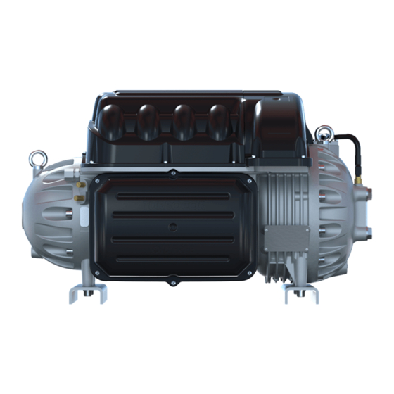
- Page 1 Applications and Installation Manual - Revision Q Danfoss Turbocor® Twin-Turbine Centrifugal Compressors TTS/TGS/TTH/TGH Compressors ® http://turbocor.danfoss.com...
- Page 2 List of Changes Revision Date Page Description of Change 06-12-2019 Redevelopment of manual to include TTH/TGH compressors 12-12-2019 Update to include TG490 and Medium Temp 04-06-2020 Major Revision H upgrade 2 of 114 M-AP-001-EN Rev. Q...
-
Page 3: Table Of Contents
Table of Contents Chapter 1.0 Introduction ........................11 1.1 Scope ........................................11 1.2 Organization of this Manual .................................11 1.3 Document Symbols ..................................11 Chapter 2.0 Overview of the TTS/TGS/TTH/TGH Compressor ............17 2.1 TTS/TGS/TTH/TGH Compressor Nomenclature ........................17 2.2 Refrigerant Type ....................................18 2.3 Environment ......................................19 2.4 Mains Plate Sealing..................................19 2.5 Configurations of the TTS/TGS/TTH/TGH Compressor Models ..................20 2.6 Compressor Module ..................................20... - Page 4 Chapter 13.0 System Design Guidelines..................61 13.1 General Requirements .................................61 13.2 Economizer Option ..................................62 13.3 Motor/Electronics Cooling Requirements ..........................62 13.4 Electrical Requirements ................................63 13.5 Application-Specific Requirements ............................63 Chapter 14.0 Sample Refrigeration Circuits ..................65 Chapter 15.0 Sound and Power Specifications ................75 15.1 TTS300 and TTS400 Sound Power Measurements ......................75 Chapter 16.0 Physical Data .......................79 16.1 Clearance ......................................79 16.2 Torque Specifications ...................................92...
- Page 5 List of Tables Table 1-1 Application Manual Applicability ..........................11 Table 1-2 Acronyms and Terms ................................13 Table 2-1 Refrigerant Used with Turbocor Compressors ......................18 Table 3-1 Backplane LEDs..................................27 Table 4-1 Control Wiring Details ................................31 Table 4-2 Jumper Details ..................................31 Table 5-1 Discharge Pressure Alarm and Trip Settings ......................35 Table 5-2 Discharge Temperature Trip Settings ...........................36 Table 5-3 Maximum Pressure Ratio Limits .............................36 Table 5-4 Maximum Allowable Pressure [PS] ..........................36...
- Page 6 List of Figures Figure 2-1 Old Type Code to New Type Code Rev. D ........................17 Figure 2-2 Compressor Nomenclature ............................18 Figure 2-3 Major Components ................................20 Figure 3-1 Compressor Fluid Path TGS230/TTS300 ........................21 Figure 3-2 Compressor Fluid Path (TGS310, TTS350, TGS390, TGS490, TTS400, TGS520, and TTS700) ....22 Figure 3-3 Compressor Cooling Circuit (TGS230 / TTS300) .....................23 Figure 3-4 Compressor Cooling Circuit (TTS300 Split-Cooling, TGS310, TTS350, TGS390, TGS490, TTS400, TT700, and TGS520) ................................23...
- Page 7 Figure 20-5 Motor-Cooling Connection and Access Port .......................102 Figure 20-6 Compressor I/O Board Connections ........................103 Figure 20-7 Interlock and Motor Speed Connections ......................104 Figure 20-8 Interlock Circuit Tests ..............................105 Figure 20-9 Typical Electrical Connections ..........................106 Figure 20-10 Ground Post Nuts ................................106 Figure 20-11 Compressor AC Input Terminals ..........................107 Figure A-1 Line Reactor Connections ............................109 Figure B-1 Interconnection Layout ..............................111...
- Page 8 THIS PAGE INTENTIONALLY LEFT BLANK 8 of 114 M-AP-001-EN Rev. Q...
- Page 9 Copyright laws of the United States of America (USA) and most other countries. This work is owned by Danfoss LLC, and was published as of the most recent revision of this publication, as indicated on the Title page of this document. This document is for the use Danfoss LLC customers and prospective customers only.
- Page 10 THIS PAGE INTENTIONALLY LEFT BLANK 10 of 114 M-AP-001-EN Rev. Q...
-
Page 11: Chapter 1.0 Introduction
(to 1 KV high power AC & DC) as well as complex control systems. Some potential safety situations may not be foreseen or covered in this guide. Danfoss LLC assumes personnel using this manual and working on Danfoss LLC compressors are familiar with, and carry out all safe work practices necessary to ensure safety for personnel and equipment. - Page 12 • • • DANGER • • • WARNING: Indicates an essential operating or maintenance procedure, practice, or condition which, if not strictly observed, could result in serious damage or destruction of equipment. • • • WARNING • • • CAUTION: Indicates an essential operating or maintenance procedure, practice, or condition which, if not strictly observed, could result in damage to equipment or potential problems in the outcome of the procedure being performed.
-
Page 13: Table 1-2 Acronyms And Terms
Table 1-2 Acronyms and Terms Acronym / Term Definition Alarms indicate a condition at the limit of the normal operating envelope. compressor Alarms alarms will still allow the compressor to run, but speed is reduced to bring the alarm condition under the alarm limit. AHRI Air-Conditioning, Heating, and Refrigeration Institute (www.ari.org;... - Page 14 Acronym / Term Definition Electromagnetic Compatibility Electromotive Force Electromagnetic Interference EMI Filter A circuit or device that provides electromagnetic noise suppression for an electronic device. Extended Performance Compressor ETL Testing Laboratories, now a mark of Intertek Testing Services. Electronic Expansion Valve. Pressure-independent refrigerant metering device driven by electrical input.
- Page 15 A software program provided by Danfoss LLC that can be downloaded to a PC or laptop Monitor Program computer to monitor, regulate, control or verify the operation of a compressor.
- Page 16 Vaneless Diffuser Similar to a Vaned Diffuser, except that it does not possess any de-swirl vanes. Volts Direct Current Variable Frequency Drive * Danfoss Turbocor’s commitment to excellence ensures continuous product improvements. * Subject to change without notice. 16 of 114...
-
Page 17: Chapter 2.0 Overview Of The Tts/Tgs/Tth/Tgh Compressor
Chapter 2.0 Overview of the TTS/TGS/TTH/TGH Compressor The TTS/TGS/TTH/TGH Centrifugal series of compressors is a group of compressors that covers the nominal capacity range from 90 to 200 Tons (TTS/TTH) and 70 to 150 Tons (TGS/TGH). This series of compressors are an oil free centrifugal design based on magnetic bearing technology. As of May 6, 2019, the product nomenclature changed. -
Page 18: Refrigerant Type
Turbocor TTS/TGS Series Figure 2-2 Compressor Nomenclature Type Code T T S 3 0 0 G E S 1 S 0 1 0 X 0 X X S 1 2 3 1 2 3 4 5 6 10 11 12 13 14 15 16 17 18 19 20 21 22 Product Series and Capacity (characters 1-6) TTS300 : TT Series 300 Aero Config Software (character 19-22) -
Page 19: Environment
Power must be applied to all compressors on the chiller for a minimum of 24 hours prior to starting the compressors. NOTE • Contact Danfoss Turbocor for lower ambient temperature operations. Refer to “Operating Envelopes, ” for details of the operating conditions. These conditions are in line with the AHRI 540 Standard. -
Page 20: Configurations Of The Tts/Tgs/Tth/Tgh Compressor Models
2.5 Configurations of the TTS/TGS/TTH/TGH Compressor Models The compressor, motor, and power assemblies are packaged in design. • • • CAUTION • • • It is important to take all precautions to avoid refrigerant migration, especially on air-cooled units. If the compressor is filled with liquid, there is a high risk of bearing damage, thus putting the compressor out of service. -
Page 21: Chapter 3.0 Functional Description
Chapter 3.0 Functional Description Compressor operation begins with a call for cooling from a chiller controller. The compressor controller then begins compressor ramp-up. 3.1 Main Fluid Path The following paragraphs describe the flow of refrigerant from the intake to the discharge port of the compressor (refer to see "Figure 3-1 Compressor Fluid Path TGS230/TTS300"... -
Page 22: Motor Cooling
Figure 3-2 Compressor Fluid Path (TGS310, TTS350, TGS390, TGS490, TTS400, TGS520, and TTS700) Volute Assembly Discharge Port High - Pressure / High - Temperature Low - Pressure / Low - Temperature Gas 2nd Stage Impeller Inlet Guide Vanes (IGV) Vaneless Diffuser 1st Stage Impeller De-swirl Vanes 3.2 Motor Cooling... -
Page 23: Figure 3-3 Compressor Cooling Circuit (Tgs230 / Tts300)
Figure 3-3 Compressor Cooling Circuit (TGS230 / TTS300) Liquid Refrigerant Inlet Solenoid Solenoid BMCC ORIFICE ORIFICE From Inverter Temp. Sensor Inverter BMCC From Motor From Motor Winding Temp. Cavity Temp. Sensor Sensor Motor/Rotor cooling gas and leakage Figure 3-4 Compressor Cooling Circuit (TTS300 Split-Cooling, TGS310, TTS350, TGS390, TGS490, TTS400, TT700, and TGS520) Liquid Refrigerant Inlet... -
Page 24: Inlet Guide Vanes
Figure 3-5 Compressor Cooling Circuit (TGH285 / TTH375) High Lift Cooling Circuit Flow Diagram Solenoid Inverter Inlet (Liquid Refrigerant) Inverter Temp Sensor Solenoid BMCC Motor Cavity Temp. Sensor Impeller Impeller Stage Stage 3.3 Inlet Guide Vanes Radial Axial Bearing Stator/Rotor Bearing Radial The Inlet Guide Vane (IGV) assembly is a variable-angle guiding device that is used for capacity control. -
Page 25: Figure 3-6 Compressor Control System Functional Block Diagram
Figure 3-6 Compressor Control System Functional Block Diagram External Power Components Surge Suppressor Motor Drive 3-Phase Line 380-575VAC 1.35*V Reactor 50/60 Hz Variable 460-853 VDC Frequency 3-Phase 3-Phase EMI/EMC Half-Controlled DC Link (0-750Hz) Inverter 380-575VAC Filter Rec�fier 0 VDC Capacitors AC Voltage 0 VDC 50/60 Hz... - Page 26 3.4.3 Bearing Motor Compressor Controller The hardware and software for the compressor controller and the bearing/motor controller physically reside in the BMCC. The BMCC is the central processor of the compressor. 3.4.4 Compressor Control The Compressor Controller is continuously updated with critical data from external sensors that indicate the compressor’s operating status.
-
Page 27: Magnetic Bearing System
3.4.11 Serial Driver The Serial Driver module performs serial-to-parallel conversion on the stepper motor drive signals from the BMCC. The module also contains four normally open relays under BMCC control. Two of the relays drive the motor-cooling solenoids, and the other two are used to indicate compressor fault status and running status. -
Page 28: Figure 3-8 Magnetic Bearing Control System
3.5.2 Bearing Control System The Bearing Control System uses rotor position feedback to close the loop and maintain the rotor in the correct running position (refer to "Figure 3-8 Magnetic Bearing Control System"). The Bearing Controller issues position commands to the Bearing PWM Amplifier. The position commands consist of five channels with each channel allocated to one of the five bearing actuator coils (one coil for each axis). -
Page 29: Chapter 4.0 Control Interface Wiring
Chapter 4.0 Control Interface Wiring The Compressor I/O Board is the entry point for control wiring from the chiller/plant to the compressor. Refer to Figures 4-1 and 4-2 for the proper Compressor I/O Board connectivity. Figure 4-1 Typical Control Wiring RS232 Monitoring Connector (DB9) EXV Phase 1A EXV #1... -
Page 30: Figure 4-2 Modbus Grounding Diagram
Figure 4-2 Modbus Grounding Diagram Retain Termination Jumper in Last Board Shield Shield Shield 120Ω CIM Board CIM Board CIM Board Termination Resistor should only be included Remove Termination if one is not included in the PLC. If the PLC Jumper in All has a resistor installed, do not add an addi- Intermediate Boards... -
Page 31: Table 4-1 Control Wiring Details
Table 4-1 Control Wiring Details Description COM (shield) Shield for RS-485 communication. Modbus RS-485 NetB/NetA Modbus over RS-485 communication port. Stepper Motor 1 Phase 1A, 1B, 2A, Optional output connections for controlling the main electronic expansion 2B and valve (evaporator) or auxillary electronic expansion valve (economizer or load Stepper Motor 2 Phase 1A, 1B, balancing valve). -
Page 32: Control Wiring Connection Guidelines
4.1 Control Wiring Connection Guidelines To ensure proper control wiring techniques, follow these guidelines: The ground reference of the external circuit connected to the Compressor I/O Board must be at the same potential as the ground reference on the Compressor I/O Board. The Interlock circuit should be voltage-free. -
Page 33: Compressor I/O Board Mounting Details
4.3 Compressor I/O Board Mounting Details The Compressor I/O Board (Figure 4-4) must be installed in a Underwriters Laboratories (UL) approved electrical enclosure equipped with DIN EN 50022, 50035, or 50045 mounting rails. The board should be mounted in a dry area, free from vibration and electrical noise. NOTE The UL listed enclosure should protect against moisture and other corrosive elements. - Page 34 THIS PAGE INTENTIONALLY LEFT BLANK 34 of 114 M-AP-001-EN Rev. Q...
-
Page 35: Chapter 5.0 General Specifications
Chapter 5.0 General Specifications 5.1 Construction • Compressor - Semi-hermetic design • Main Housing - Dimensionally-stabilized aluminum • Covers - High-impact, UV stabilized, flame-resistant polymer. • Covers - High-impact, UV stabilized, flame- resistant polymer. TGS series is identified by green cover. •... -
Page 36: Maximum Discharge Temperature
5.3 Maximum Discharge Temperature The maximum temperature that the compressor can operate is regulated directly by the Trip Limit. The Maximum Discharge Temperature Limits are defined in "Table 5-2 Discharge Temperature Trip Settings". Table 5-2 Discharge Temperature Trip Settings Unit Compressor TGS230ST TGS230MT TGS310 TGS490 TGS390 TGS520 TGH285 TTS300ST TTS300MT TTS350 TTS400 TTS700 TTH375 °F Trip °C... -
Page 37: Suction Pressure Limits
(e.g., cruise ships, floating platforms). Danfoss Turbocor compressors are produced for civilian use and are not intended for safety critical systems. Misapplication of a Turbocor compressor will not be covered under Danfoss LLC’s Standard Warranty Terms and Conditions. - Page 38 THIS PAGE INTENTIONALLY LEFT BLANK 38 of 114 M-AP-001-EN Rev. Q...
-
Page 39: Chapter 6.0 Electrical Specifications
Application of a compressor to any voltage which is outside of the nominal rated voltage defined on the compressor nameplate will result in voiding of the compressor warranty from Danfoss LLC, unless otherwise stated by Danfoss LLC. This includes any application of a 400V compressor in a 380V application without the use of a transformer to correct the voltage going into the compressor. -
Page 40: Disconnects
Table 6-3 FLA and LRA Value Range Default Model Voltage Max* TGS230 380V TGS230 400V TGS230 460V TGS230 575V TGS310 380V TGS310 400V TGS310 460V TGS390 380V TGS390 400V TGS390 460V TGS390 575V TGS490 380V TGS490 400V TGS490 460V TGS520 380V TGS520 400V... -
Page 41: Motor Insulation Class
Although all Turbocor compressors are Conformance European (CE) listed, the compliance of the compressor with the EMC directive depends on the use of the CE EMI/EMC filter provided by Danfoss LLC (see spare parts manual for further details). If this is not possible because of the nature of your application and/or installation, an alternative component with the same attenuation characteristics must be used to maintain compliance with the EMC Directive. -
Page 42: Surge Protection
If it is necessary to provide additional current harmonic reduction beyond that provided by the standard 5% line reactor, Danfoss LLC recommends the installation of a harmonic filter device in parallel with the compressor as shown in "Figure 20-9 Typical Electrical Connections" on page 106. -
Page 43: Equipment Panel
Therefore, Danfoss LLC advises to use some type of shielded cable for the mains input. -
Page 44: Idle Power Consumption
The mains input cable should be CSA, UL, or CE approved, three-wire with a common shield and single ground. The cable must be rated for 90°C (194°F) minimum at the maximum applicable current. It is recommended that the cable be double-jacketed, e.g., teck cable type. Refer to "Table 6-4 Main Cable Connector Plate Hole Sizes"... -
Page 45: Chapter 7.0 Compressor Performance
Chapter 7.0 Compressor Performance 7.1 Performance Ratings Compressor performance, including applicable capacity range, varies based on the operating conditions. The capacity range, efficiency, and other operational information for each compressor can be determined only by using the authorized software known as the “Compressor Performance Rating Engine”... - Page 46 THIS PAGE INTENTIONALLY LEFT BLANK 46 of 114 M-AP-001-EN Rev. Q...
-
Page 47: Chapter 8.0 Operating Envelopes
Chapter 8.0 Operating Envelopes Figure 8-1 Operating Envelope, TTS300 and TGS230 NOTE The maximum SDT of the operating envelope represents the limit for compressors with maximum FLA settings. The SDT for a compressor with a lower maximum current rating is lower than that shown and is related to the FLA rating of the particular compressor. -
Page 48: Figure 8-2 Operating Envelope, Tts300 And Tgs230 (Medium Temperature Compressor)
Figure 8-2 Operating Envelope, TTS300 and TGS230 (Medium Temperature Compressor) The actual obtainable capacity will be dependent on specific operating characteristics of each compressor model. Refer to the current authorized compressor selection/rating software for more exact values and conditions. 48 of 114 M-AP-001-EN Rev. -
Page 49: Figure 8-3 Operating Envelope, Tts350, Tgs310
Figure 8-3 Operating Envelope, TTS350, TGS310 , and TGS490 NOTE The maximum SDT of the operating envelope represents the limit for compressors with maximum FLA settings. The SDT for a compressor with a lower maximum current rating is lower than that shown and is related to the FLA rating of the particular compressor. -
Page 50: Figure 8-4 Operating Envelope, Tts400 And Tgs390
Figure 8-4 Operating Envelope, TTS400 and TGS390 NOTE The maximum SDT of the operating envelope represents the limit for compressors with maximum FLA settings. The SDT for a compressor with a lower maximum current rating is lower than that shown and is related to the FLA rating of the particular compressor. -
Page 51: Figure 8-5 Operating Envelope, Tts700 And Tgs520
Figure 8-5 Operating Envelope, TTS700 and TGS520 NOTE The maximum SDT of the operating envelope represents the limit for compressors with maximum FLA settings. The maximum SDT for compressors with an FLA less than that is lower than the upper bound of the operating envelope and depends on the FLA rating. -
Page 52: Figure 8-6 Operating Envelope, Tth375/Tgh285
Figure 8-6 Operating Envelope, TTH375/TGH285 NOTE The maximum SDT of the operating envelope represents the limit for compressors with maximum FLA settings. The maximum SDT for compressors with an FLA less than that is lower than the upper bound of the operating envelope and depends on the FLA rating. -
Page 53: Chapter 9.0 Minimum Unloading Capacity
Chapter 9.0 Minimum Unloading Capacity Due to the nature of centrifugal compression, the minimum stable load is dependent on the pressure ratio imposed on the compressor by the chiller system. All compressor performance, including unloading, should be determined through use of the relevant compressor selection/rating programs. 53 of 114 M-AP-001-EN Rev. - Page 54 THIS PAGE INTENTIONALLY LEFT BLANK 54 of 114 M-AP-001-EN Rev. Q...
-
Page 55: Chapter 10.0 Control Logic Guidelines For Multiple Compressors
NOTE Danfoss LLC highly recommends the use of a solenoid valve as a staging valve as it is faster to provide pressure relief to the compressor in case of emergency shutdown. We recommend to command the Solenoid valve with the "compressor status"... - Page 56 THIS PAGE INTENTIONALLY LEFT BLANK 56 of 114 M-AP-001-EN Rev. Q...
-
Page 57: Chapter 11.0 Product Certification
Chapter 11.0 Product Certification All TTS/TGS/TTH/TGH Series compressors are ETL and CE listed and have been tested in accordance with UL Standard 984 and CSA Standard C22.2. 57 of 114 M-AP-001-EN Rev. Q... - Page 58 THIS PAGE INTENTIONALLY LEFT BLANK 58 of 114 M-AP-001-EN Rev. Q...
-
Page 59: Chapter 12.0 Guide Specifications
IGVs shall be built-in to further trim the compressor capacity in conjunction with the variable-speed control to optimize compressor performance at low loads. Refer to Danfoss LLC Selection Software for performance calculations and limits. 12.5 Compressor Motor The compressor shall be provided with a direct-drive, high-efficiency, permanent-magnet synchronous motor powered by PWM voltage supply. -
Page 60: Compressor Electronics
12.6 Compressor Electronics The compressor shall include a microprocessor controller capable of controlling magnetic bearings and speed control. The controller shall be capable of providing monitoring, including commissioning assistance, energy outputs, operation trends, and fault codes via a Modbus interface. 12.6.1 Ancillary Devices A check valve shall be installed on the discharge port of all compressors to protect against backflow of refrigerant during coast down. -
Page 61: Chapter 13.0 System Design Guidelines
NOTE The compressor internal safety control settings are designed to provide protection for the compressor only. Designers MUST provide SYSTEM protection within their control design. Danfoss LLC will not be responsible for system protection other than the compressor. 13.1 General Requirements Check for compliance with all installation, operating, commissioning, and service steps, as outlined in the documentation set. -
Page 62: Economizer Option
To determine compressor capacity and efficiency, the economizer performance rating option is available in the Selection Software on the TT/TG Software Section of the Danfoss LLC web page (www. turbocoroem.com). The circuit must be properly designed to reflect the specified heat exchanger approach with minimized pressure drops across the liquid side and expansion side. -
Page 63: Electrical Requirements
The motor/electronics cooling outlet port is fitted with a 5/8” flare adapter. NOTE Danfoss LLC highly recommends the insulation of the suction and inter-stage pipe as well as the bottom of the compressor for MT applications to prevent ice buildups. -
Page 64: Table 13-2 Low Lift Pump Sizing
If more capacity is desired, it is advisable to raise the discharge pressure temporarily to increase the pressure ratio (point B) until the sensible heat in the building is dissipated. Figure 13-2 Centrifugal Performance Dynamics NOTE Contact Danfoss LLC for compressor selection and technical advice. 64 of 114 M-AP-001-EN Rev. Q... -
Page 65: Chapter 14.0 Sample Refrigeration Circuits
Chapter 14.0 Sample Refrigeration Circuits Figure 14-1 Typical Refrigeration Piping Schematic Discharge Port Economizer Motor Cooling Port Port Suction Port Sight Glass Filter/ Drier Staging Check Valve Valve Evaporator Optional configuration for Low Lift operation (CC 4.1 & later) Check Valve Expansion ... -
Page 66: Figure 14-2 Typical Refrigeration Piping Schematic With Staging And Load Balancing Valve
Figure 14-2 Typical Refrigeration Piping Schematic With Staging and Load Balancing Valve Discharge Port Economizer Motor Cooling Port Port Suction Port Sight Sight Glass Glass Filter/ Filter/ Drier Drier Check Valve Evaporator Staging Staging Valve Valve Load Load Balancing Balancing Valve Valve Condenser with... -
Page 67: Figure 14-3 Typical Refrigeration Piping Schematic With Flash Tank Economizer
Figure 14-3 Typical Refrigeration Piping Schematic With Flash Tank Economizer Discharge Port Economizer Motor Cooling Port Port Suction Port Sight Glass Filter/ Drier Check Valve Staging Evaporator Solenoid Valve Valve Condenser with Subcooler Filter/ Drier Expansion ... -
Page 68: Figure 14-4 Typical Refrigeration Piping Schematic With Closed Type Economizer
Figure 14-4 Typical Refrigeration Piping Schematic With Closed Type Economizer Discharge Port Economizer Motor Cooling Port Port Suction Port Sight Glass Filter/ Drier Check Staging Valve Valve Evaporator Condenser with Subcooler Expansion Valve Sight Glass Solenoid ... -
Page 69: Figure 14-5 Typical Refrigeration Piping Schematic Using Motor-Cooling Pressure Regulating Valve (Tts300/Tgs230 Medium Temperature Compressors Only)
Figure 14-5 Typical Refrigeration Piping Schematic Using Motor-Cooling Pressure Regulating Valve (TTS300/TGS230 Medium Temperature Compressors Only) Discharge Port Motor Cooling Pressure Port Regulating Valve Sight Glass Filter/ Suction Drier Port Economizer Check Port Valve Evaporator ... -
Page 70: Figure 14-6 Typical Refrigeration Piping Schematic Using Motor-Cooling Pressure Regulating Valve (Tth/Tgh Medium Temperature Compressors Only)
Figure 14-6 Typical Refrigeration Piping Schematic Using Motor-Cooling Pressure Regulating Valve (TTH/TGH Medium Temperature Compressors Only) Motor Cooling Port Sight Discharge Port Glass Pressure Regulating Valve Suction Port Economizer Filter/ Port Drier Evaporator Check Staging Valve Valve Expansion ... -
Page 71: Figure 14-7 Typical Refrigeration Piping Schematic With Multiple Dx Evaporators
Figure 14-7 Typical Refrigeration Piping Schematic With Multiple DX Evaporators Discharge Port Economizer Motor Cooling Port Port Suction Port Sight Glass Filter/ Drier Staging Valve Check Valve Evaporator Expansion Valve Condenser with Subcooler Expansion ... -
Page 72: Figure 14-8 Multiple Compressors Single Circuit Piping Schematic
Port Port Port (with integral (with integral Motor Cooling Motor Cooling strainer) strainer) Port Port Evaporator Sight Glass NOTE Contact Danfoss LLC for compressor selection and further technical advice. NOTE *Service valves are optional. 72 of 114 M-AP-001-EN Rev. Q... -
Page 73: Figure 14-9 Tth/Tgh Piping Schematic With Required Economizer (Closed Type) And Vapor Line Solenoid
Figure 14-9 TTH/TGH Piping Schematic with Required Economizer (Closed Type) and Vapor Line Solenoid Motor Cooling Suction Discharge Port Port Port Sight Glass Check Valve Evaporator Filter/ Drier Economizer Port Staging Valve Expansion Valve Sight Glass Condenser with ... -
Page 74: Figure 14-10 Tth/Tgh Piping Schematic With Required Economizer (Flash Tank) And Vapor Line Solenoid
Figure 14-10 TTH/TGH Piping Schematic with Required Economizer (Flash Tank) and Vapor Line Solenoid Motor Cooling Port Discharge Port Sight Sight Glass Glass Suction Port Check Valve Filter/ Filter/ Economizer Drier Drier Port Staging Valve Evaporator Solenoid Solenoid Valve Valve Economizer Condenser with Tank... -
Page 75: Chapter 15.0 Sound And Power Specifications
Chapter 15.0 Sound and Power Specifications 15.1 TTS300 and TTS400 Sound Power Measurements The sound power levels on the TTS300 and TTS400 compressors are measured in compliance with ISO 9614-1 (1993) and are given in decibels and in A-scale dB(A). Three series of sound power measurements were performed on the unit while in two (2) different modes: •... -
Page 76: Table 15-3 Sound Power At Third Octave Band, Tts300 Compressor
Table 15-3 Sound Power at Third Octave Band, TTS300 Compressor Sound Power, 250kW (70 Ton) Sound Power, 315kW (90 Ton) Third octave band Third octave band Linear scale (dB) A-weighted (dBA) Linear scale (dB) A-weighted (dBA) (Hz) (Hz) 55.5 41.8 59.6 45.8 62.0... -
Page 77: Table 15-6 Sound Power At Third Octave Band Of Tts400 Compressor
Table 15-6 Sound Power at Third Octave Band of TTS400 Compressor Sound Power, 420kW (120 Ton) Sound Power, 525kW (150 Ton) Third octave band Third octave band Linear scale (dB) A-weighted (dBA) Linear scale (dB) A-weighted (dBA) (Hz) (Hz) 1000 1000 1250 1250... - Page 78 THIS PAGE INTENTIONALLY LEFT BLANK 78 of 114 M-AP-001-EN Rev. Q...
-
Page 79: Chapter 16.0 Physical Data
Chapter 16.0 Physical Data This section contains data relative to compressor mounting, service clearance, and piping connections. NOTE The dimensions in the following figures show measurements in imperial with metric in parenthesis. Table 16-1 Physical Dimensions Compressor Weight Compressor Including I/O Cable Shipping Total Weight Kg Model... -
Page 80: Figure 16-2 Service Side View (Excluding Tth/Tgh Compressors)
Figure 16-2 Service Side View (Excluding TTH/TGH Compressors) 2 0 6 . 0 8 ( 8 . 1 1 ” ) MOTOR COOLING FITTING SIZE 1/2" SWEAT CONNECTION Front view Scale: 1:2 4 8 4 . 3 5 ( 1 9 . 0 7 ” ) 1 5 0 . -
Page 81: Figure 16-4 Tth/Tgh Suction Side View
Figure 16-4 TTH/TGH Suction Side View 7 9 . 9 9 6 ( 3 . 1 5 " ) Front view Scale: Figure 16-5 TTH/TGH Service Side View 7 0 5 . 5 ( 2 7 . 7 8 " ) 5 8 . -
Page 82: Figure 16-6 Tth/Tgh Second Stage Housing View
Figure 16-6 TTH/TGH Second Stage Housing View 5 8 9 . 5 6( 2 3 . 2 1 ” ) 2 2 0( 8 . 6 6 ” ) Front view Scale: 1 5 0( 5 . 9 ” ) 3 0 0( 1 1 . -
Page 83: Figure 16-8 Center Of Gravity Capacitor Side View (Excluding Tth/Tgh Compressors)
Figure 16-8 Center of Gravity Capacitor Side View (Excluding TTH/TGH Compressors) 7 8 7 ( 3 0 . 9 8 ” ) 2 2 0 . 2 ( 8 . 6 7 ” ) 1 6 7 ( 6 . 5 7 ” ) Rear view Scale: 1 5 0 . -
Page 84: Figure 16-10 Tth/Tgh Center Of Gravity Capacitor Side View
Figure 16-10 TTH/TGH Center of Gravity Capacitor Side View 7 0 5 . 7 ( 2 7 . 7 8 " ) Left view Scale: Figure 16-11 TTH/TGH Center of Gravity Top View 4 8 4 . 3 5 ( 1 9 . 0 7 " ) 1 8 2 . -
Page 85: Table 16-2 Center Of Gravity X-Y Coordinates
Table 16-2 Center of Gravity X-Y Coordinates TGS490/ TTS300/ TTS400/ TTS700/ TTH375/ Description Parameter TTS350/ TGS230 TGS390 TGS520 TGH285 TGS310 Length of Center of Gravity m (in) 257 mm (10.13") 249 mm (9.80") 247 mm (9.74") 251mm (9.87") 182.3 mm (7.18") Width of Center of Gravity m (in) 151 mm (5.95") 153.1 mm (6.03") -
Page 86: Figure 16-13 Discharge Port Detail (Tts350 And Tgs310)
Figure 16-13 Discharge Port Detail (TTS350 and TGS310) Gas Flow Figure 16-14 Discharge Port Detail (TTS400 and TGS390) Gas Flow 86 of 114 M-AP-001-EN Rev. Q... -
Page 87: Figure 16-15 Discharge Port Detail (Tts700, Tgs490, And Tgs520)
Figure 16-15 Discharge Port Detail (TTS700, TGS490, and TGS520) Gas Flow Figure 16-16 Discharge Port Detail (TTH375 and TGH285) ø 72.075 (2.84”) ø 36 1.41”) 90° 87 of 114 M-AP-001-EN Rev. Q... -
Page 88: Figure 16-17 Suction Port (All Models)
Figure 16-17 Suction Port (All Models) 88 of 114 M-AP-001-EN Rev. Q... -
Page 89: Figure 16-18 Suction Port Detail Dd (All Models Excluding Tts700 And Tgs520)
Figure 16-18 Suction Port Detail DD (All Models Excluding TTS700 and TGS520) Gas Flow Figure 16-19 Suction Port Detail DD (TTS700, TGS490, and TGS520) Gas Flow 89 of 114 M-AP-001-EN Rev. Q... -
Page 90: Figure 16-20 Tts300 And Tgs230 Flange Footprint Details
Figure 16-20 TTS300 and TGS230 Flange Footprint Details Figure 16-21 TTS350,TGS310,TTS400,TGS390, TTH375, and TGH285 Flange Footprint Details 90 of 114 M-AP-001-EN Rev. Q... -
Page 91: Table 16-3 Screw Hole Specifications
Figure 16-22 TTS700, TGS490, and TGS520 Flange Footprint Details Table 16-3 Screw Hole Specifications Port Fastner Thread Spec Thread Depth (mm) Recommended Torque (Nm) Suction 34.5 Discharge Economizer • • • WARNING • • • Refer to the manufacturer fastener specifications and torque as required, but do not exceed the torque values listed in "Table 16-3 Screw Hole Specifications". -
Page 92: Torque Specifications
16.2 Torque Specifications Table 16-4 Torque Specifications Description Ft.Lb. In.Lb. IGV and End Bell Bolts Pressure/Temp Sensor IGV Power Feedthrough Bearing Power and Sensor Feedthroughs Cavity Sensor E-Housing and Later SCR Mounting Screws A/C Bus Bars DC Capacitors and Bleed Resistor IGBT Mounting Screws Shraeder Valves Motor Cooling Body (Body Nut), E-Housing and Later*... -
Page 93: Chapter 17.0 Piping Considerations
The motor-cooling line should be channeled from the liquid line; refer to Section "13.1 General Requirements" on page 61 for more information. Danfoss LLC requires the installation of a sight glass and full-flow liquid dryer in the motor-cooling line. - Page 94 THIS PAGE INTENTIONALLY LEFT BLANK 94 of 114 M-AP-001-EN Rev. Q...
-
Page 95: Chapter 18.0 Environmental Considerations
Chapter 18.0 Environmental Considerations 18.1 Humidity If the compressor is installed in a humid environment, drip trays may be required to collect condensate. Insulation should be installed on the suction valve/piping and the end cap as this is where condensation is most likely to form. It is recommended to fit an End Cap insulator in a humid environment. - Page 96 THIS PAGE INTENTIONALLY LEFT BLANK 96 of 114 M-AP-001-EN Rev. Q...
-
Page 97: Chapter 19.0 Shipping Considerations
Danfoss LLC suggests the temporary installation of an anti-vibration bracket between the compressor’s base frame and mounting rail during transit, as shown in "Figure 19-1 Anti- Vibration Bracket". - Page 98 THIS PAGE INTENTIONALLY LEFT BLANK 98 of 114 M-AP-001-EN Rev. Q...
-
Page 99: Chapter 20.0 Installation
The compressor should be carefully inspected for visible signs of damage. Check for loose bolts and damage to covers or the outer casing. Damage should first be reported to the carrier, not Danfoss LLC. You can contact Danfoss LLC Customer Support and Service to assist in determining the extent of damage or if the compressor should be returned to Danfoss LLC. -
Page 100: Mounting Base
20.4 Mounting Base The compressor must be mounted on a rigid surface of sufficient structural integrity to support the weight of the compressor and valves (refer to "Figure 16-8 Center of Gravity Capacitor Side View (Excluding TTH/TGH Compressors)", "Figure 16-9 Center of Gravity Top View (Excluding TTH/TGH Compressors)", "Figure 16-10 TTH/TGH Center of Gravity Capacitor Side View", "Figure 16-11 TTH/ TGH Center of Gravity Top View", and "Table 16-2 Center of Gravity X-Y Coordinates"). -
Page 101: Piping Connections
Figure 20-4 Correct Compressor Mounting Pad Installation Screw Compressor Spring Mounting Rail Washer Flat Washer Rubber Mount Base Frame In the event the mounting base is not used and the compressor is secured directly to the chiller, refer to the fastener specifications in "Table 16-5 Mounting Base Screw Hole Specifications". Table 16-5 Mounting Base Screw Hole Specifications Fastner Thread Spec Thread Depth (mm) -
Page 102: Control Wiring
Figure 20-5 Motor-Cooling Connection and Access Port Motor Cooling Inlet Schrader Valves 20.6 Control Wiring The compressor I/O board enables communication of control and status signals between the compressor controller and external equipment. These signals include, among others, cooling demand, input, stepper motor control inputs and outputs, alarm and interlock contacts, and Modbus protocol communications. -
Page 103: Figure 20-6 Compressor I/O Board Connections
Figure 20-6 Compressor I/O Board Connections Compressor I/O Board Interface Cable 103 of 114 M-AP-001-EN Rev. Q... -
Page 104: Figure 20-7 Interlock And Motor Speed Connections
20.6.2 Circuit Grounding Improper grounding or voltage in circuits connected to the compressor I/O board can lead to component failures. In particular, the interlock and analog output circuits are sensitive to improperly connected external circuits (refer to "Figure 20-7 Interlock and Motor Speed Connections"). Prior to connecting the control wiring to the compressor I/O board, check for improper grounding. -
Page 105: Power Wiring
Keep power cables and control interface cables in separate conduits. Use metal cable glands for shielded cables to ensure good grounding. If you are installing a Danfoss LLC line reactor or EMI or harmonic filter in the mains input circuit, refer to the applicable installation instructions. -
Page 106: Figure 20-9 Typical Electrical Connections
Figure 20-9 Typical Electrical Connections Surge Suppressor (optional) Connect power wiring ground and ground of secondary transformer, including 24 control power Fuse (User-supplied) to common ground point in electrical panel. EMI/EMC AC Input Filter Voltage (optional) Circuit Protection (**) Line Fast-acting fuses (*) Reactor Manual Disconnect... -
Page 107: Figure 20-11 Compressor Ac Input Terminals
Figure 20-11 Compressor AC Input Terminals TTS300/TGS230 Compressors All TTS/TGS/TTH/TGH Models Prior to Revision H (Except TTS300/TGS230) Mains Stud - 3/8- 16 - 1.5” long Mains Input AC Input Pressure Connection Screw Upper Nut & Jam Nut Terminal Block Adapter Seal Bracket Opening All TTS/TGS/TTH/TGH Models, Revision H... - Page 108 THIS PAGE INTENTIONALLY LEFT BLANK 108 of 114 M-AP-001-EN Rev. Q...
-
Page 109: Figure A-1 Line Reactor Connections
Appendix A: A.1 Line Reactor Installation Instructions These instructions apply to the installation of the line reactor kit in a main supply panel. See the Spare Parts Selection Guide for product specifications. A.1.1 AC Line Cable Connection (From External Disconnect) NOTE The customer is responsible for supplying the mounting hardware for the line reactor. - Page 110 THIS PAGE INTENTIONALLY LEFT BLANK 110 of 114 M-AP-001-EN Rev. Q...
-
Page 111: Figure B-1 Interconnection Layout
Appendix B: B.1 EMI/EMC Filter Installation Instructions Mount the filter on the floor or on a wall in a vertical position. Ensure there is a minimum of 60mm (2 3/8”) of space for the cooling slots. B.1.1 Line Side Connection Input and output filter leads should be separated by a maximum practical distance within the enclosure and should be routed separately in interconnecting conduits when used (refer to "Figure B-1 Interconnection Layout"). -
Page 112: Figure B-2 Grounding Diagram
Figure B-2 Grounding Diagram Short Heavy Grounding Diagram Braided Cable Filter Ground Lug Main Ground Bus 112 of 114 M-AP-001-EN Rev. Q... - Page 113 Quick access to Danfoss Turbocor® troubleshooting. compressor The new version of the Danfoss TurboTool® 2.0 app for all your full service Danfoss Turbocor® compressor needs. 24/7 Access to Danfoss Turbocor® The user can select from a list The TurboTool® app makes...
- Page 114 Our products can be found in a variety of applications such as rooftops, chillers, residential air conditioners, heat pumps, coldrooms, supermarkets, milk tank cooling and industrial cooling processes. http://turbocor.danfoss.com Danfoss Turbocor 1769 E. Paul Dirac Drive 1769, Tallahassee FL 32310 USA | +1 850 504 4800 © Danfoss | DCS (CC) | 2020.05 M-AP-001-EN Rev. Q...
Need help?
Do you have a question about the TGS Series and is the answer not in the manual?
Questions and answers