
Subscribe to Our Youtube Channel
Related Manuals for Danfoss Turbocor TTS Series


Summary of Contents for Danfoss Turbocor TTS Series
- Page 1 Applications and Installation Manual - Revision S Danfoss Turbocor® Twin-Turbine Centrifugal Compressors TTS/TGS/TTH/TGH Compressors ® http://turbocor.danfoss.com |...
- Page 2 THIS PAGE INTENTIONALLY LEFT BLANK Page 2 of 136 - M-AP-001-EN Rev. S 9/8/2021...
-
Page 3: Table Of Contents
Table of Contents Table of Contents Chapter 1.0 Introduction 1.1 Scope 1.2 Document Symbols Chapter 2.0 Compressor Overview 2.1 TTS/TGS/TTH/TGH Compressor Nomenclature 2.2 Refrigerant Type 2.3 Environment 2.4 Configurations of the TTS/TGS/TTH/TGH Compressor Models 2.5 Compressor Module Chapter 3.0 Functional Description 3.1 Main Fluid Path 3.2 Motor Cooling 3.3 Inlet Guide Vanes... - Page 4 3.5.1 Overview 3.5.2 Bearing Control System Chapter 4.0 Control Interface Wiring 4.1 Control Wiring Connection Guidelines 4.2 Interface Cable 4.3 Compressor I/O Board Mounting Details 4.3.1 Compressor I/O Board Mounting Instructions Chapter 5.0 General Specifications 5.1 Construction 5.2 Maximum Pressure 5.3 Maximum Discharge Temperature 5.4 Suction Pressure Limits 5.5 Standards Compliance...
- Page 5 Chapter 7.0 Compressor Performance 7.1 Performance Ratings 7.2 Tolerance of Performance Ratings Chapter 8.0 Operating Envelopes Chapter 9.0 Minimum Unloading Capacity Chapter 10.0 Control Logic Guidelines for Multiple Compressors Chapter 11.0 Product Certification Chapter 12.0 Guide Specifications 12.1 General 12.2 Refrigerant 12.3 Compressor Bearings 12.4 Capacity Control 12.5 Compressor Motor...
- Page 6 Chapter 16.0 Physical Data 16.1 Clearance Chapter 17.0 Piping Considerations Chapter 18.0 Environmental Considerations 18.1 Humidity 18.2 Vibration Chapter 19.0 Shipping Considerations 19.1 Vibration Chapter 20.0 Installation 20.1 Unpacking and Inspection 20.2 Rigging Requirements 20.3 Unit Placement 20.4 Mounting Base 20.5 Piping Connections 20.6 Control Wiring 20.6.1 Control Wiring Connections...
- Page 7 List of Changes Revision Date Page Description of Change 06-12-2019 Redevelopment of manual to include TTH/TGH compressors 12-12-2019 Update to include TG490 and Medium Temp 04-06-2020 Major Revision H upgrade 02-01-2021 Includes High SST and general review/update 07-29-2021 Complete review/many Includes new TTS 575V small changes made option...
- Page 8 THIS PAGE INTENTIONALLY LEFT BLANK Page 8 of 136 - M-AP-001-EN Rev. S 9/8/2021...
- Page 9 In any event, the total aggregate liability for all damages of any kind and type (regardless of whether based in contract or tort) of Danfoss LLC, shall not exceed the purchase price of this product.
- Page 10 THIS PAGE INTENTIONALLY LEFT BLANK Page 10 of 136 - M-AP-001-EN Rev. S 9/8/2021...
-
Page 11: Chapter 1.0 Introduction
(to 1 KV high power AC & DC) as well as complex control systems. Some potential safety situations may not be foreseen or covered in this guide. Danfoss LLC assumes personnel using this manual and working on Danfoss LLC compressors are familiar with, and carry out, all safe work practices necessary to ensure safety for personnel and equipment. - Page 12 DANGER: Indicates an essential operation or maintenance procedure, practice, or condition which, if not strictly observed, could result in injury to or death of personnel or long-term health hazards. A Danger notification is displayed in the format shown below. • • • DANGER! • • • CAUTION: Indicates an essential operation or maintenance procedure, practice, or condition which, if not strictly observed, could result in damage to or destruction of equipment or potential problems in the outcome of the procedure being performed.
- Page 13 Acronym/Term Definition overheat protection to motor windings. Conformance European. The CE marking (also known as CE mark) is a mandatory conformity mark on many products placed on the single market in the European (EU) Economic Area. The CE marking certifies that a product has met EU health, safety, and environmental requirements, which ensure consumer safety.
- Page 14 Acronym/Term Definition Electromotive Force. Electromagnetic Interference. EMI Filter A circuit or device that provides electromagnetic noise suppression for an electronic device. EPDM Ethylene propylene diene monomer – type of synthetic rubber. ETL Testing Laboratories, now a mark of Intertek Testing Services. Electronic Expansion Valve.
- Page 15 Monitor Program A software program provided by Danfoss LLC that can be downloaded to a PC or laptop computer to monitor, regulate, control or verify the operation of a compressor.
- Page 16 Acronym/Term Definition Motor Back EMF Back electromotive force is a voltage that occurs in electric motors where there is relative motion between the armature of the motor and the external magnetic field and is also a parameter used to evaluate the strength of the permanent magnets of the shaft. One practical application is to use this phenomenon to indirectly measure motor speed as well as estimate position.
- Page 17 Acronym/Term Definition expansion valves. It contains four relays for the solenoid valves, compressor status and compressor run status respectively. Saturated Discharge Temperature. Service Monitor Tools a PC program provided byDanfoss LLC. A user friendly way of displaying compressor data to the user and offer adjustment of predetermined parameters.
- Page 18 Acronym/Term Definition Volts Direct Current. Variable Frequency Drive. Watt. Page 18 of 136 - M-AP-001-EN Rev. S 9/8/2021...
-
Page 19: Chapter 2.0 Compressor Overview
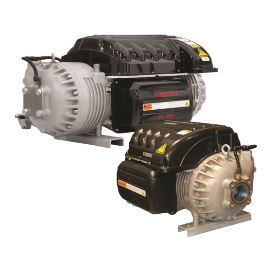
Chapter 2.0 Compressor Overview The TTS/TGS/TTH/TGH Centrifugal series of compressors is a group of compressors that covers the nominal capacity range from 90 to 200 Tons (TTS/TTH) and 70 to 150 Tons (TGS/TGH). This series of compressors are an oil free centrifugal design based on magnetic bearing technology. - Page 20 Figure 2-2 Compressor Nomenclature Page 20 of 136 - M-AP-001-EN Rev. S 9/8/2021...
-
Page 21: Refrigerant Type
Ensure all covers are in place and secured. The Danfoss Turbocor compressors have integrated seals in each cover which prevent ingress of moisture and contaminants; however, if the covers are not in place and properly secured, outside air and contaminates can intrude and potentially affect the electronics. -
Page 22: Configurations Of The Tts/Tgs/Tth/Tgh Compressor Models
Figure 2-3 Mains Plate Sealing NOTE Contact Danfoss LLC Applications for lower ambient temperature operations. Refer to Figure Operating Envelopes. in this manual for details of the operating conditions. These conditions are in line with the AHRI 540 Standard. All compressors/components should be protected from environments that could cause corrosion to exposed metals. For outdoor installations, a weather-proof enclosure with vents is recommended to house the compressor. -
Page 23: Compressor Module
Figure 2-4 Major Components 2.5 Compressor Module This section provides a brief overview of the Compressor Module. The Compressor Module is comprised of three portions: Aerodynamics - The aerodynamics portion manages the refrigerant compression process from the suction to the discharge including the inlet guide vane assembly. Motor - The motor portion contains a direct-drive, high-efficiency, permanent-magnet synchronous motor powered by pulse-width-modulating (PWM) voltage supply. - Page 24 THIS PAGE INTENTIONALLY LEFT BLANK Page 24 of 136 - M-AP-001-EN Rev. S 9/8/2021...
-
Page 25: Chapter 3.0 Functional Description
Chapter 3.0 Functional Description Compressor operation begins with a call for cooling from a chiller controller. The compressor controller then begins compressor ramp-up. 3.1 Main Fluid Path The following paragraphs describe the flow of refrigerant from the intake to the discharge port of the compressor (refer to Figure 3-1 Compressor Fluid Path TGS230/TTS300 and Figure 3-2 Compressor Fluid Path (TGS310, TTS350, TGS390, TGS490, TTS400, TGS520, and TTS700). -
Page 26: Motor Cooling
Figure 3-2 Compressor Fluid Path (TGS310, TTS350, TGS390, TGS490, TTS400, TGS520, and TTS700) Table 3-2 Compressor Fluid Path (TGS310, TTS350, TGS390, TGS490, TTS400, TGS520, and TTS700) Description Description Low-Pressure/Low Temperature Gas Second-Stage Impeller First-Stage Impeller Vaneless Diffuser Volute Assembly Discharge Port Vanes High-Pressure/High Temperature Gas 3.2 Motor Cooling... - Page 27 From the outlet of the orifices, the refrigerant is directed to the heatsink plate of the inverter and to the underside of the SCR heatsink. The refrigerant also passes through grooves surrounding the motor stator. As the refrigerant flows through the grooves, it vaporizes into a gas. At the coil outlet, the refrigerant gas is channeled back to the suction inlet via the motor cavity, thereby cooling the rotor.
- Page 28 Figure 3-4 Compressor Cooling Circuit (TTS300 Split-Cooling, TGS310, TTS350, TGS390, TGS490, TTS400, TTS700, and TGS520) Table 3-4 Compressor Cooling Circuit (TTS300 Split-Cooling, TGS310, TTS350, TGS390, TGS490, TTS400, TTS700, and TGS520) Description Description From Motor Winding Temp Sensor From Inverter Temp Sensor BMCC Solenoid M Motor/Rotor Cooling Gas and Leakage...
-
Page 29: Inlet Guide Vanes
Figure 3-5 Highlift Cooling Circuit Flow Diagram (TGH285/TTH375) Table 3-5 Highlift Cooling Circuit Flow Diagram (TGH285/TTH375) Description Description Solenoid M Radial Bearing Liquid Refrigerant Inlet Axial Bearing Solenoid E Impeller - 1 Stage Inverter Motor Cavity Temp. Sensor BMCC Impeller - 2 Stage Inverter Temp Sensor Radial Bearing... -
Page 30: Compressor Control Overview
3.4 Compressor Control Overview Refer to Figure 3-6 Compressor Control System Functional Block Diagram which shows a functional block diagram of the compressor control and monitoring system. Refer to Figure 3-8 Magnetic Bearing Control System which displays the component locations. The major components include: Motor Drive Soft-Start Board BMCC... -
Page 31: Soft Start
Because of the close integration between the compressor and the VFD, Danfoss LLC cannot support the use of non-integrated VFDs due to the extensive development required to ensure the same functionality and reliability as the standard integrated VFD. -
Page 32: Monitoring Functions
3.4.8 Monitoring Functions The Compressor Controller monitors more than 60 parameters, including: Gas pressure and temperature monitoring Line voltage monitoring and phase failure detection Motor temperature Line currents External interlock 3.4.9 Abnormal Conditions The Compressor Controller responds to abnormal conditions by monitoring: Surge RPMs Choke RPMs Power failure/phase unbalance... -
Page 33: High-Voltage Dc-Dc Converter
Table 3-6 Backplane LEDs Function +5V, +15V, +17HV, +24V LEDs are lighted when DC power is available. Cool-H, Cool-L LEDs are lighted when their respective coil is energized. LED is lighted when the shaft is spinning. Alarm LED is green when in normal status, red when in alarm status. D13, D14, D15, D16 LEDs indicate IGV status and flash when IGV is moving. - Page 34 allocated to one of the five bearing actuator coils (one coil for each axis). The amplifier uses Inverter technology to convert the low-voltage position commands to the 250VDC PWM signals that are applied to each bearing actuator coil. Rotor position sensors are located on rings attached to the front and rear radial bearing assemblies. The front sensor ring contains sensors that read the rotor position along the X, Y, and Z axes.
-
Page 35: Chapter 4.0 Control Interface Wiring
Chapter 4.0 Control Interface Wiring The Compressor I/O Board is the entry point for control wiring from the chiller/plant to the compressor. Refer to Figure 4-1 Typical Control Wiring. Figure 4-2 Modbus Grounding Diagram for the proper Compressor I/O Board connectivity. - Page 36 Figure 4-2 Modbus Grounding Diagram Table 4-1 Control Wiring Details Description COM (shield) Shield for RS-485 communication. Modbus RS-485 Modbus over RS-485 communication port. NetB/NetA Stepper Motor 1 Phase Optional output connections for controlling the main electronic expansion valve (evaporator) or auxiliary 1A, 1B, 2A, 2B, and electronic expansion valve (economizer or load balancing valve).
-
Page 37: Control Wiring Connection Guidelines
Description thermistor. An internal N/O contact that is closed while the compressor is running. The speed at which the contact closes is user-configurable via the monitor program. Circuit rated at 1A @ 30VDC/24VAC or 0.3A @ 120VAC. Analog Universal analog output manually controlled as a percentage of total voltage written through Modbus. This can be configured for 0-5V or 0-10V via on board jumpers. -
Page 38: Interface Cable
4. All interlock and analog output cables should be shielded with one end of the shield connected to the common analog or digital ground bus. The other end of the shield must not be grounded as this would create a ground loop. Refer to Figure 4-2 Modbus Grounding Diagram. 4.2 Interface Cable The cable that carries the I/O communication to the compressor is 5 meters (16.4 feet) in length and is equipped with high-density 44-pin connectors (female at one end and male at the other end). -
Page 39: Compressor I/O Board Mounting Details
4.3 Compressor I/O Board Mounting Details The Compressor I/O Board ( Figure 4-4 Compressor I/O Board) must be installed in a Underwriters Laboratories (UL) approved electrical enclosure equipped with DIN EN 50022, 50035, or 50045 mounting rails. The board should be mounted in a dry area, free from vibration and electrical noise. - Page 40 THIS PAGE INTENTIONALLY LEFT BLANK Page 40 of 136 - M-AP-001-EN Rev. S 9/8/2021...
-
Page 41: Chapter 5.0 General Specifications
Chapter 5.0 General Specifications 5.1 Construction Compressor - Semi-hermetic design Main Housing - Dimensionally-stabilized aluminum Covers - High-impact, UV stabilized, flame-resistant polymer (TGS series is identified by green cover) Shaft - High-strength alloy Impellers - High-strength aluminum Motor - Permanent magnet, synchronous, DC Bearings - Integrated, digitally-controlled, magnetic Compressor Control - Integrated, digital capacity control Enclosure - IP54 rating... -
Page 42: Suction Pressure Limits
Table 5-2 Discharge Temperature Fault Settings Unit Compressor TGS230ST TGS230MT TGS310 TGS490 TGS390 TGS520 TGH285 TTS300ST TTS300MT TTS350 TTS400 TTS700 TTH375 °F Fault °C Fault NOTE While the values here are represented in Gauge Pressure, the values in the registers will be defined in Absolute Pressure. Refer to the OEM Programming Manual to identify the specific registers associated with the Discharge Pressure Alarm and Discharge Pressure Fault Limits. -
Page 43: Standards Compliance
All TTS/TGS/TTH/TGH Series Turbocor compressors were designed for use in stationary building applications and are suitable for some marine applications (e.g., cruise ships, floating platforms). Danfoss Turbocor compressors are produced for civilian use and are not intended for safety critical systems. Misapplication of a Turbocor compressor will not be covered under Danfoss LLC’s Standard Warranty Terms and Conditions. - Page 44 THIS PAGE INTENTIONALLY LEFT BLANK Page 44 of 136 - M-AP-001-EN Rev. S 9/8/2021...
-
Page 45: Chapter 6.0 Electrical Specifications
Application of a compressor to any voltage which is outside of the nominal rated voltage defined on the compressor nameplate will result in voiding of the compressor warranty from Danfoss LLC, unless otherwise stated by Danfoss LLC. This includes any application of a 400V compressor in a 380V application without the use of a transformer to correct the voltage going into the compressor. - Page 46 Table 6-3 FLA and LRA Value Range Default Model Voltage Max* TGS230 380V TGS230 400V TGS230 460V TGS230 575V TGS310 380V TGS310 400V TGS310 460V TGS310 575V TGS390 380V TGS390 400V TGS390 460V TGS390 575V TGS490 380V TGS490 400V TGS490 460V TGS520 380V...
-
Page 47: Disconnects
Default Model Voltage Max* TTS400 575V TTS700 380V TTS700 400V TTS700 460V TTS700 575V TTH375 380V TTH375 400V TTH375 460V TTH375 575V NOTE Refer to the OEM Programming Manual to identify specific registers associated with the “3-Phase Over Current Alarm (FLA) and 3-Phase Over Current Fault (LRA).”... -
Page 48: Power Line Contactor
Although all Turbocor compressors are Conformance European (CE) listed, the compliance of the compressor with the EMC directive depends on the use of the CE EMI/EMC filter provided by Danfoss LLC. If this is not possible because of the nature of your application and/or installation, an alternative component with the same attenuation characteristics must be used to maintain compliance with the EMC Directive. -
Page 49: Surge Protection
If it is necessary to provide additional current harmonic reduction beyond that provided by the standard 5% line reactor, Danfoss LLC recommends the installation of a harmonic filter device in parallel with the compressor as shown in Figure 20-9 Typical Electrical Connections. The rule of selecting the Harmonic filter is: PFilter_Rated [kW] = LRA [A]*URated [V]*1.73*0.9/1000. -
Page 50: Equipment Panel
Figure 6-1 Typical Ground Connections NOTE Application of Turbocor compressors in any power system without a standard earth ground system should be reviewed and approved by the Turbocor application organization. 6.13 Equipment Panel Normally, the line reactor, EMI/EMC filter(s), and the harmonic filter will be installed in a panel. This could be the same panel where the controls are located. -
Page 51: Mains Input Cable Specification
Therefore, Danfoss LLC advises to use some type of shielded cable for the mains input. - Page 52 THIS PAGE INTENTIONALLY LEFT BLANK Page 52 of 136 - M-AP-001-EN Rev. S 9/8/2021...
-
Page 53: Chapter 7.0 Compressor Performance
Chapter 7.0 Compressor Performance 7.1 Performance Ratings Compressor performance, including applicable capacity range, varies based on the operating conditions. The capacity range, efficiency, and other operational information for each compressor can be determined only by using the authorized software known as the Compressor Performance Rating (CPR) Engine or CPR Engine. This software and a selection tool is available on our website. - Page 54 THIS PAGE INTENTIONALLY LEFT BLANK Page 54 of 136 - M-AP-001-EN Rev. S 9/8/2021...
-
Page 55: Chapter 8.0 Operating Envelopes
Engineer for expert guidance. Danfoss LLC has recently developed several variants of our compressors, each of which is designed to operate in a specific Saturated Suction Temperature (SST) range. Danfoss LLC strongly urges selecting a compressor which covers the range of SST expected for the application. - Page 56 Figure 8-1 Operating Envelope , Standard SST: TTS300 and TGS230 NOTE The maximum Saturated Discharge Temperature (SDT) of the operating envelope represents the limit for compressors with maximum FLA settings. The SDT for a compressor with a lower maximum current rating is lower than that shown and is related to the FLA rating of the particular compressor.
- Page 57 Figure 8-2 Operating Envelope , Medium Temperature: TTS300 and TGS230 NOTE The maximum SDT of the operating envelope represents the limit for compressors with maximum FLA settings. The SDT for a compressor with a lower maximum current rating is lower than that shown and is related to the FLA rating of the particular compressor.
- Page 58 Figure 8-3 Operating Envelope , Standard SST: TT350, TGS310, and TGS490 NOTE The maximum SDT of the operating envelope represents the limit for compressors with maximum FLA settings. The SDT for a compressor with a lower maximum current rating is lower than that shown and is related to the FLA rating of the particular compressor.
- Page 59 Figure 8-4 Operating Envelope , High SST: TTS350, TGS310, and TGS490 NOTE The maximum SDT of the operating envelope represents the limit for compressors with maximum FLA settings. The SDT for a compressor with a lower maximum current rating is lower than that shown and is related to the FLA rating of the particular compressor.
- Page 60 Figure 8-5 Operating Envelope , Standard SST: TTS400 and TGS390 NOTE The maximum SDT of the operating envelope represents the limit for compressors with maximum FLA settings. The SDT for a compressor with a lower maximum current rating is lower than that shown and is related to the FLA rating of the particular compressor.
- Page 61 (1), Figure 8-6 Operating Envelope High SST: TTS400 and TGS390 NOTE The maximum SDT of the operating envelope represents the limit for compressors with maximum FLA settings. The SDT for a compressor with a lower maximum current rating is lower than that shown and is related to the FLA rating of the particular compressor.
- Page 62 Figure 8-7 Operating Envelope , Standard SST: TTS700 and TGS520 NOTE The maximum SDT of the operating envelope represents the limit for compressors with maximum FLA settings. The SDT for a compressor with a lower maximum current rating is lower than that shown and is related to the FLA rating of the particular compressor.
- Page 63 Figure 8-8 Operating Envelope , High SST: TTS700, and TGS520 NOTE The maximum SDT of the operating envelope represents the limit for compressors with maximum FLA settings. The SDT for a compressor with a lower maximum current rating is lower than that shown and is related to the FLA rating of the particular compressor.
- Page 64 (1), Figure 8-9 Operating Envelope Standard SST: TTH375/TGH285 NOTE The maximum SDT of the operating envelope represents the limit for compressors with maximum FLA settings. The SDT for a compressor with a lower maximum current rating is lower than that shown and is related to the FLA rating of the particular compressor.
- Page 65 (1), Figure 8-10 Operating Envelope Medium Temperature: TTH375/TGH285 NOTE The maximum SDT of the operating envelope represents the limit for compressors with maximum FLA settings. The SDT for a compressor with a lower maximum current rating is lower than that shown and is related to the FLA rating of the particular compressor.
- Page 66 THIS PAGE INTENTIONALLY LEFT BLANK Page 66 of 136 - M-AP-001-EN Rev. S 9/8/2021...
-
Page 67: Chapter 9.0 Minimum Unloading Capacity
Chapter 9.0 Minimum Unloading Capacity Due to the nature of centrifugal compression, the minimum stable load is dependent on the pressure ratio imposed on the compressor by the chiller system. All compressor performance, including unloading, should be determined through use of the relevant compressor selection/rating programs. M-AP-001-EN Rev. - Page 68 THIS PAGE INTENTIONALLY LEFT BLANK Page 68 of 136 - M-AP-001-EN Rev. S 9/8/2021...
-
Page 69: Chapter 10.0 Control Logic Guidelines For Multiple Compressors
NOTE Danfoss LLC highly recommends the use of a solenoid valve as a staging valve as it is faster to provide pressure relief to the compressor in case of emergency shutdown. We recommend to command the Solenoid valve with the "compressor status" contact on the I/O board. - Page 70 THIS PAGE INTENTIONALLY LEFT BLANK Page 70 of 136 - M-AP-001-EN Rev. S 9/8/2021...
-
Page 71: Chapter 11.0 Product Certification
Chapter 11.0 Product Certification All TTS/TGS/TTH/TGH Series compressors are ETL listed and CE marked and have been tested in accordance with UL 60335-2-34:2017 Ed.6, CSA C22.2 No. 60335-2-34:2017 Ed.2 and EN 60335-2-34:2013. M-AP-001-EN Rev. S-9/8/2021 Page 71 of 136... - Page 72 THIS PAGE INTENTIONALLY LEFT BLANK Page 72 of 136 - M-AP-001-EN Rev. S 9/8/2021...
-
Page 73: Chapter 12.0 Guide Specifications
Capacity modulates infinitely as motor speed is varied across the range. IGVs shall be built-in to further trim the compressor capacity in conjunction with the variable-speed control to optimize compressor performance at low loads. Refer to Danfoss LLC Selection Software for performance calculations and limits. - Page 74 THIS PAGE INTENTIONALLY LEFT BLANK Page 74 of 136 - M-AP-001-EN Rev. S 9/8/2021...
-
Page 75: Chapter 13.0 System Design Guidelines
The compressor internal safety control settings are designed to provide protection for the compressor only. Designers MUST provide SYSTEM protection within their control design. Danfoss LLC will not be responsible for system protection other than the compressor. 13.1 General Requirements 1. -
Page 76: Economizer Option
To determine compressor capacity and efficiency, the economizer performance rating option is available in the Selection Software on the TT/TG Software Section of the Danfoss LLC web page (www. turbocoroem.com). The circuit must be properly designed to reflect the specified heat exchanger approach with minimized pressure drops across the liquid side and expansion side. -
Page 77: Electrical Requirements
5/8” flare adapter. NOTE Danfoss LLC highly recommends the insulation of the suction and inter-stage pipe as well as the bottom of the compressor for MT applications to prevent ice buildups. 13.5.2 High Evaporating Temperature Application (TGS310/TTS350/TGS490/TGS390/TTS400/TGS520/TTS700) NOTE High Evaporating Temperature is defined as between 12 and 30°C (53.6 and 86°F) and only applies to... -
Page 78: Limited Capacity At Low Pressure Ratios
13.5.3 Limited Capacity at Low Pressure Ratios Figure 13-2 Centrifugal Performance Dynamics illustrates the capacity reduction imposed by compressor logic when a compressor is operated at low lift conditions without a low lift pump and without the low lift function activated. - Page 79 Figure 13-2 Centrifugal Performance Dynamics NOTE Contact Danfoss LLC Applications for compressor selection and technical advice. M-AP-001-EN Rev. S-9/8/2021 Page 79 of 136...
- Page 80 THIS PAGE INTENTIONALLY LEFT BLANK Page 80 of 136 - M-AP-001-EN Rev. S 9/8/2021...
-
Page 81: Chapter 14.0 Sample Refrigeration Circuits
Chapter 14.0 Sample Refrigeration Circuits Figure 14-1 Typical Refrigeration Piping Schematic NOTE * Service valves are optional M-AP-001-EN Rev. S-9/8/2021 Page 81 of 136... - Page 82 Figure 14-2 Typical Refrigeration Piping Schematic with Staging and Load Balancing Valve NOTE * Service valves are optional Page 82 of 136 - M-AP-001-EN Rev. S 9/8/2021...
- Page 83 Figure 14-3 Typical Refrigeration Piping Schematic with Flash Tank Economizer NOTE * Service valves are optional M-AP-001-EN Rev. S-9/8/2021 Page 83 of 136...
- Page 84 Figure 14-4 Typical Refrigeration Piping Schematic with Closed Type Economizer NOTE * Service valves are optional Page 84 of 136 - M-AP-001-EN Rev. S 9/8/2021...
- Page 85 Figure 14-5 Typical Refrigeration Piping Schematic Using Motor-Cooling Pressure Regulating Valve (TTS300/TGS230 Medium Temperature Compressors Only) NOTE * Service valves are optional M-AP-001-EN Rev. S-9/8/2021 Page 85 of 136...
- Page 86 Figure 14-6 Typical Refrigeration Piping Schematic Using Motor-Cooling Pressure Regulating Valve (TTH/TGH Medium Temperature Compressors Only) NOTE * Service valves are optional Closed type economizer shown; open type can also be used Page 86 of 136 - M-AP-001-EN Rev. S 9/8/2021...
- Page 87 Figure 14-7 Typical Refrigeration Piping Schematic with Multiple DX Evaporators NOTE * Service valves are optional M-AP-001-EN Rev. S-9/8/2021 Page 87 of 136...
- Page 88 Figure 14-8 Multiple Compressors Single Circuit Piping Schematic NOTE Contact Danfoss LLC for compressor selection and further technical advice NOTE * Service valves are optional Page 88 of 136 - M-AP-001-EN Rev. S 9/8/2021...
- Page 89 Figure 14-9 TTH/TGH Piping Schematic with Required Economizer (Closed Type) and Vapor Line Solenoid NOTE Failure to include a solenoid valve in the compressor VAPOR line, wired to close immediately when the compressor shuts down, could result in serious damage to the compressor. NOTE All TGH/TTH compressors MUST include an active economizer (flash or plate style) when operated at pressure ratios above 2.0.
- Page 90 Figure 14-10 TTH/TGH Piping Schematic with Required Economizer (Flash Tank) and Vapor Line Solenoid NOTE * Service valves are optional Page 90 of 136 - M-AP-001-EN Rev. S 9/8/2021...
-
Page 91: Chapter 15.0 Sound And Power Specifications
Chapter 15.0 Sound and Power Specifications 15.1 TTS300 and TTS400 Sound Power Measurements The sound power levels on the TTS300 and TTS400 compressors are measured in compliance with ISO 9614-1 (1993) and are given in decibels and in A-scale dB(A). Three series of sound power measurements were performed on the unit while in two (2) different modes: For TTS300: 250kW (70 ton) refrigeration capacity 315kW (90 ton) refrigeration capacity... - Page 92 Table 15-3 Sound Power at Third Octave Band for TTS300 Sound Power, 250kW (70 Ton) Sound Power, 315kW (90 Ton) Linear scale Linear scale Third octave band (Hz) A-weighted (dBA) Third octave band (Hz) A-weighted (dBA) (dB) (dB) 55.5 41.8 59.6 45.8 62.0...
- Page 93 Table 15-6 Sound Power at Third Octave Band for TTS400 Sound Power, 420kW (120 Ton) Sound Power, 525kW (150 Ton) Linear scale Linear scale Third octave band (Hz) A-weighted (dBA) Third octave band (Hz) A-weighted (dBA) (dB) (dB) 1000 1000 1250 1250 1600...
- Page 94 THIS PAGE INTENTIONALLY LEFT BLANK Page 94 of 136 - M-AP-001-EN Rev. S 9/8/2021...
-
Page 95: Chapter 16.0 Physical Data
Chapter 16.0 Physical Data This section contains data relative to compressor mounting, service clearance, and piping connections. NOTE The dimensions in the following figures show measurements in metric with imperial in parenthesis. Table 16-1 Physical Dimensions Shipping Weight Compressor Total Model Length Width... - Page 96 Figure 16-1 Suction View All Models (Excluding TTH/TGH Compressors) Figure 16-2 Service Side View (Excluding TTH/TGH Compressors) Page 96 of 136 - M-AP-001-EN Rev. S 9/8/2021...
- Page 97 Figure 16-3 Discharge Side View (Excluding TTH/TGH Compressors) Figure 16-4 TTH/TGH Suction Side View M-AP-001-EN Rev. S-9/8/2021 Page 97 of 136...
- Page 98 Figure 16-5 TTH/TGH Service Side View Figure 16-6 TTH/TGH Second Stage Housing View Page 98 of 136 - M-AP-001-EN Rev. S 9/8/2021...
- Page 99 Figure 16-7 TTH/TGH Discharge Side View Figure 16-8 Center of Gravity Capacitor Side View (Excluding TTH/TGH Compressors) M-AP-001-EN Rev. S-9/8/2021 Page 99 of 136...
- Page 100 Figure 16-9 Center of Gravity Top View (Excluding TTH/TGH Compressors) Figure 16-10 TTH/TGH Center of Gravity Capacitor Side View Page 100 of 136 - M-AP-001-EN Rev. S 9/8/2021...
- Page 101 Figure 16-11 TTH/TGH Center of Gravity Top View Table 16-2 Center of Gravity X-Y Coordinates TTS300/ TGS490/ TTS350/ TTS400/ TTS700/ TTH375/ Description Parameter TGS230 TGS310 TGS390 TGS520 TGH285 Length of Center of 257 mm 249 mm (9.80") 247 mm 251mm 182.3 mm Gravity m (in) (10.13")
- Page 102 Figure 16-12 Discharge Port Detail (TTS300 and TGS230) Figure 16-13 Discharge Port Detail (TTS350 and TGS310) Page 102 of 136 - M-AP-001-EN Rev. S 9/8/2021...
- Page 103 Figure 16-14 Discharge Port Detail (TTS400 and TGS390) Figure 16-15 Discharge Port Detail (TTS700, TGS490, and TGS520) M-AP-001-EN Rev. S-9/8/2021 Page 103 of 136...
- Page 104 Figure 16-16 Discharge Port Detail (TTH375 and TGH285) Figure 16-17 Suction Port (All Models) Page 104 of 136 - M-AP-001-EN Rev. S 9/8/2021...
- Page 105 Figure 16-18 Suction Port Detail (All Models Excluding TTS700, TGS490, and TGS520) Figure 16-19 Suction Port Detail (TTS700, TGS490, and TGS520) M-AP-001-EN Rev. S-9/8/2021 Page 105 of 136...
- Page 106 Figure 16-20 TTS300 and TGS230 Flange Footprint Details Figure 16-21 TTS350, TGS310, TTS400, TGS390, TTH375, and TGH285 Flange Footprint Details Page 106 of 136 - M-AP-001-EN Rev. S 9/8/2021...
- Page 107 Figure 16-22 TTS700, TGS490, and TGS520 Flange Footprint Details Table 16-3 Screw Hole Specifications Port Fastener Thread Spec Thread Depth (mm) Recommended Torque (Nm) Suction 34.5 Discharge Economizer • • • CAUTION • • • Refer to the manufacturer fastener specifications and torque as required, but do not exceed the torque values listed in Table 16-3 Screw Hole Specifications."...
- Page 108 Table 16-4 Torque Specifications Description Ft.Lb. In.Lb IGV and End Bell Fasteners Pressure/Temp Sensor IGV Power Feedthrough Bearing Power and Sensor Feedthroughs Cavity Sensor E-Housing and Later SCR Mounting Fasteners A/C Bus Bars DC Capacitors and Bleed Resistors Inverter Mounting Fasteners Schaeder Valves Motor Cooling Body (Body Nut), E-Housing and Later* Motor Cooling Compression Nut, E-Housing and Later* Cover Plate...
-
Page 109: Chapter 17.0 Piping Considerations
Sample Refrigeration Circuits provides examples of compressor piping arrangements for the most common applications. The motor-cooling line should be channeled from the liquid line; refer to Section 13.1 General Requirements for more information. Danfoss LLC Applications requires the installation of a sight glass and full-flow liquid dryer in the motor-cooling line. NOTE Some applications may require alternative arrangements. - Page 110 THIS PAGE INTENTIONALLY LEFT BLANK Page 110 of 136 - M-AP-001-EN Rev. S 9/8/2021...
-
Page 111: Chapter 18.0 Environmental Considerations
Chapter 18.0 Environmental Considerations 18.1 Humidity If the compressor is installed in a humid environment, drip trays may be required to collect condensate. Insulation should be installed on the suction valve/piping and the end cap as this is where condensation is most likely to form. It is recommended to fit an End Cap insulator in a humid environment. - Page 112 THIS PAGE INTENTIONALLY LEFT BLANK Page 112 of 136 - M-AP-001-EN Rev. S 9/8/2021...
-
Page 113: Chapter 19.0 Shipping Considerations
Due to the flexibility of the compressor’s isolation mounts, compressor vibration during transit can fracture the motor cooling line’s rigid piping. Danfoss LLC Applications suggests the temporary installation of an anti-vibration bracket between the compressor’s base frame and mounting rail during transit, as shown in Figure 19-1 Anti-Vibration Bracket. - Page 114 THIS PAGE INTENTIONALLY LEFT BLANK Page 114 of 136 - M-AP-001-EN Rev. S 9/8/2021...
-
Page 115: Chapter 20.0 Installation
The compressor should be carefully inspected for visible signs of damage. Check for loose bolts and damage to covers or the outer casing. Damage should first be reported to the carrier, not Danfoss LLC. You can contact Danfoss LLC Product Support to assist in determining the extent of damage or if the compressor should be returned to Danfoss LLC. -
Page 116: Mounting Base
20.4 Mounting Base The compressor must be mounted on a rigid surface of sufficient structural integrity to support the weight of the compressor and valves. Refer to the following figures and table for further details. Figure 16-10 TTH/TGH Center of Gravity Capacitor Side View Figure 1-9 Center of Gravity Top View (Excluding TTH/TGH Compressors Figure 16-10 TTH/TGH Center of Gravity Capacitor Side View Figure 1-11 TTH/TGH Center of Gravity Top View... -
Page 117: Piping Connections
Figure 20-3 Incorrect Compressor Mounting Pad Installation Figure 20-4 Correct Compressor Mounting Pad Installation In the event the mounting base is not used and the compressor is secured directly to the chiller, refer to the fastener specifications in Table 20-1 Mounting Base Screw Hole Specifications. Table 20-1 Mounting Base Screw Hole Specifications Fastener Thread Spec Thread Depth (mm) -
Page 118: Control Wiring
1. After releasing the pressure, remove the suction and discharge connection blanking plates from the new compressor. 2. Attach the suction, discharge, and economizer (if applicable) connections. Solder all joints according to approved practice ensuring that dry nitrogen is used at all times. 3. -
Page 119: Circuit Grounding
The interface cable connects the compressor to the compressor I/O board. To connect the cable: 1. Plug the cable connector into connector J6 on the compressor I/O board. For RS-485 communication, the total length of the interface cable and control wiring can be extended up to 100 meters (328 feet) (refer to Figure 1-1 Typical Control Wiring Figure 4-3 I/O Wiring Specifications. -
Page 120: Voltage-Free Contacts
voltage is insufficient insulation of the external circuit. In case of uncertainty of the grounding, connect the negative terminals of the external circuit to a ground and then connect the external ground to the ground on the compressor I/O board. Figure 20-7 Interlock and Motor Speed Connections 20.6.3 Voltage-Free Contacts Prior to connecting the interlock terminals of the compressor I/O board, measure the resistance across the... -
Page 121: Power Wiring
Figure 20-8 Interlock Circuit Tests Measure the voltage between each customer interlock terminal and the frame ground while the interlock contacts are open and closed. In either contact state, if the measured voltage is not zero (0), verify the source of the voltage. Do not connect the interlock terminals until the voltage source is removed (refer to Figure 20-9 Typical Electrical Connections). - Page 122 Figure 20-9 Typical Electrical Connections NOTE (*) Class T 600 VAC fast-acting fuses must be installed for all models except for TGS230 and TTS300 compressors. (**) Circuit protection is required - refer to local electrical requirements. 1. Remove the fasteners that secure the cover and set the cover aside. 2.
- Page 123 Figure 20-10 Ground Post Nuts 8. The three compression lugs on the TTS300/TGS230 compressors need to be torqued to 20 Nm (15 ft- lbs). Figure 20-11 Compressor AC Input Terminals Refer to Table 20-2 Compressor AC Input Terminals for the descriptions of the items shown in Figure 20-11 Compressor AC Input Terminals and Figure All TTS/TGS/TTH/TGH Models, Revision H (Except TTS300/TGS230).
- Page 124 Figure 20-12 All TTS/TGS/TTH/TGH Models, Revision H (Except TTS300/TGS230) 9. The three 3/8”-16 nuts on all other compressors (excluding TTS300/TGS230 compressors) will need to be torqued to 21 Nm (15 ft-lbs). NOTE The bore size of the Terminal Block Adapter (TTS300 and TGS230 only) is 18 mm, therefore the maximum wire diameter must not exceed that size.
-
Page 125: Line Reactor Installation Instructions
Appendix A A.1 Line Reactor Installation Instructions These instructions apply to the installation of the line reactor kit in a main supply panel. Refer to the Spare Parts Selection Guide for product specifications. A.1.1 AC Line Cable Connection (From External Disconnect) NOTE The customer is responsible for supplying the mounting hardware for the line reactor. - Page 126 THIS PAGE INTENTIONALLY LEFT BLANK Page 126 of 136 - M-AP-001-EN Rev. S 9/8/2021...
-
Page 127: Emi/Emc Filter Installation Instructions
Appendix B B.1 EMI/EMC Filter Installation Instructions 1. Mount the filter on the floor or on a wall in a vertical position. 2. Ensure there is a minimum of 60mm (2 3/8”) of space for the cooling slots. B.1.1 Line Side Connection Input and output filter leads should be separated by a maximum practical distance within the enclosure and should be routed separately in interconnecting conduits when used (refer to Figure B-1 Interconnection Layout). - Page 128 Figure B-2 Grounding Diagram Page 128 of 136 - M-AP-001-EN Rev. S 9/8/2021...
-
Page 129: Pressure Regulating Valve Installation Instructions
Appendix C C.1 Pressure Regulating Valve Installation Instructions When installing the KVP 22, certain steps must be performed to ensure no internal valve damage occurs. 1. Remove the KVP 22 adjustment cap as shown in Figure C-1 Adjustment Cap Lift. Figure C-1 Adjustment Cap Lift 2. - Page 130 5. Slide both pipes over the stubs of the valve ensuring a minimum of a 9.5 mm (3/8”) connecting joint. 6. Wrap the valve in cool wet towels to help prevent excessive heat from damaging the valve. 7. Heat the two (2) sections of pipe and apply a (6% silver 94% tin) type solder ensuring the two (2) pipe connections are properly sealed.
- Page 131 11. Install the KVP 22 cap. Finger tight plus a ¼ turn (3Nm). • • • DANGER! • • • It is important to properly tighten the Schrader valve and the top cap. This is especially important when used with flammable refrigerants. M-AP-001-EN Rev.
- Page 132 THIS PAGE INTENTIONALLY LEFT BLANK Page 132 of 136 - M-AP-001-EN Rev. S 9/8/2021...
- Page 133 Boost your Turbocor® knowledge The Danfoss Turbocor® Training Program - Service, Maintenance, and Troubleshooting • Online and face-to-face training modules • Discover the advantages of oil-free technology • Go hands-on with a Turbocor compressor • Master the Turbocor monitoring software •...
- Page 134 THIS PAGE INTENTIONALLY LEFT BLANK Page 134 of 136 - M-AP-001-EN Rev. S 9/8/2021...
- Page 135 Quick access to Danfoss Turbocor® troubleshooting. compressor The new version of the Danfoss TurboTool® 2.0 app for all your full service 24/7 Danfoss Turbocor® compressor needs. Access to Danfoss Turbocor® The user can select from a list The TurboTool® app makes...
- Page 136 This also applies to products already on order provided that such alterations can be made without subsequential changes being necessary in specifications already agreed. All trademarks in this material are property of the respective companies. Danfoss and the Danfoss logotype are trademarks of Danfoss A/S. All rights reserved. Page 136 of 136 - M-AP-001-EN Rev. S 9/8/2021...
Need help?
Do you have a question about the Turbocor TTS Series and is the answer not in the manual?
Questions and answers