
Subscribe to Our Youtube Channel
Related Manuals for GE PACSystems RXi


Summary of Contents for GE PACSystems RXi
- Page 1 Intelligent Platforms Programmable Control Products PACSystems* RXi Distributed IO Controller ICRXICTL000 User Manual GFK-2816F August 2015...
- Page 2 Changes, modifications, and/or improvements to equipment and specifications are made periodically and these changes may or may not be reflected herein. It is understood that GE may make changes, modifications, or improvements to the equipment referenced herein or to the document itself at any time. This document is intended for trained personnel familiar with the GE products referenced herein.
- Page 4 Contact Information If you purchased this product through an Authorized Channel Partner, please contact the seller directly. General Contact Information Online technical support and GlobalCare http://support.ge-ip.com Additional information http://www.ge-ip.com/ Solution Provider solutionprovider.ip@ge.com Technical Support If you have technical problems that cannot be resolved with the information in this guide, please contact us by telephone or email, or on the web at http://support.ge-ip.com...
-
Page 6: Table Of Contents
Contents Chapter 1 Introduction ..................1 Specifications ......................2 1.1.1 Part Numbers ....................2 1.1.2 Mechanical Specifications ................2 1.1.3 RXi Controller Environmental Specifications ........... 2 1.1.4 Power Requirements ..................3 1.1.5 CPU Performance Specifications..............3 1.1.6 Communications Support ................. 3 System Version Information ..................5 RXi Controller User Features ..................6 1.3.1... - Page 7 Configuring the Embedded PNC ..............48 4.2.4 Configuring PROFINET LANs................ 54 4.2.5 Adding a GE Intelligent Platforms PROFINET Scanner to a LAN ....56 4.2.6 Adding a Third-Party IO-Device to a LAN ............59 4.2.7 Viewing / Editing IO-Device Properties ............63 4.2.8...
- Page 8 Contents 5.5.1 CPU Stop Modes ................... 81 5.5.2 Stop-to-Run Mode Transition ................. 82 Flash Memory Operation ..................83 Logic/Configuration Source and CPU Operating Mode at Power-up ...... 84 Clocks and Timers ....................86 5.8.1 Elapsed Time Clock ..................86 5.8.2 Time of Day Clock ..................
- Page 9 Contents 7.1.3 I/O Variables ....................121 7.1.4 Arrays ......................123 7.1.5 Variable Indexes and Arrays ................ 123 7.1.6 Ensuring that a Variable Index does not Exceed the Upper Boundary of an Array ......................125 Reference Memory ....................126 7.2.1 Word (Register) References ................ 126 7.2.2 Bit (Discrete) References ................
- Page 10 Contents Client Communications via the Ethernet Interface ..........150 8.6.1 Structure of the Communications Request ..........150 8.6.2 Controlling Communications in the Ladder Program ........153 8.6.3 Monitoring the Communications Channel ............ 154 8.6.4 Troubleshooting a Ladder Program ............. 155 8.6.5 Major and Minor Error Codes in the COMMREQ Status Word ....
- Page 11 Contents 10.7.4 Scan Set I/O for Remote I/O Modules ............214 10.7.5 I/O Defaults Operation ................. 214 10.8 PROFINET IO-Controller Diagnostics ..............215 10.8.1 Power-up and Reset ..................215 10.8.2 PROFINET IO-Controller Status Reporting ..........215 10.8.3 PROFINET IO Alarms .................. 216 10.8.4 PROFINET IO-Controller Faults in the Fault Tables ........
- Page 12 13.6 RXi OPC UA Server Information in Address Space ..........254 RXi OPC UA Server – Application Information ..........255 13.6.1 OPC UA Server – GE Device Information ........... 257 13.6.2 13.7 RXi OPC UA Automatic Restart Function ............. 258 13.8...
- Page 13 Contents Appendix B. PROFINET IO Performance Examples ........303 System Descriptions ....................304 B.1.1 1ms PROFINET Update Rate Systems ............304 B.1.2 16ms PROFINET Update Rate Systems ............. 305 Appendix C. User Memory Allocation .............. 307 Items that Count Against User Memory ..............307 User Program Memory Usage ................
-
Page 14: Chapter 1 Introduction
Chapter 1. Introduction Chapter 1 Introduction The RXi Controller combines the PACSystems control engine with PROFINET-based distributed I/O and gigabit Ethernet (GbE) communications into a single package. An Intelligent Display Module (IDM) with a resistive touch panel display is mounted on the RXi Controller for enhanced operator usability. -
Page 15: Specifications
Chapter 1. Introduction Specifications 1.1.1 Part Numbers ICRXICTL000 RXi Controller ICRXIACCIDM01 Intelligent Display Module (IDM) ICRXIACCBPL Optional Backplate for DIN rail mounting (rev B or later required) IC690ACC001 Real Time Clock (RTC) battery, replacement ICRXIACCEPK01A Energy Pack. Includes base, CapPack module and Energy Pack to Controller cable. -
Page 16: Power Requirements
Chapter 1. Introduction 1.1.4 Power Requirements RXi Controller with IDM 1.5 A at 24Vdc (18–30 Vdc) 36 Watts minimum power supply recommended RXI Controller with IDM and 3 A at 24Vdc (18–30 Vdc) Energy Pack 72 Watts minimum power supply recommended 1.1.5 CPU Performance Specifications Processor... - Page 17 Chapter 1. Introduction PROFINET Controller (PNC) Specifications PROFINET version PROFINET Version 2.2 General Class A IO-Controller Port connectors Two RJ-45 with 10/100/1000 Mbps. Supports PROFINET and Media Redundancy Protocol (MRP). IEEE 802.2 Logical Link Control Class I IEEE 802.3 CSMA/CD Medium Access Control 10/100/1000 Mbps Maximum I/O Memory 128 Kbytes of combined input/output memory...
-
Page 18: System Version Information
Chapter 1. Introduction System Version Information The RXi Controller’s web page can be viewed using standard web browsers. It displays component serial number and version information, and provides access to firmware updates via the Internet. Note: The following example shows an optional ICRXIACCEPK01A Energy Pack. Sample Controller Home Page GFK-2816F August 2015... -
Page 19: Rxi Controller User Features
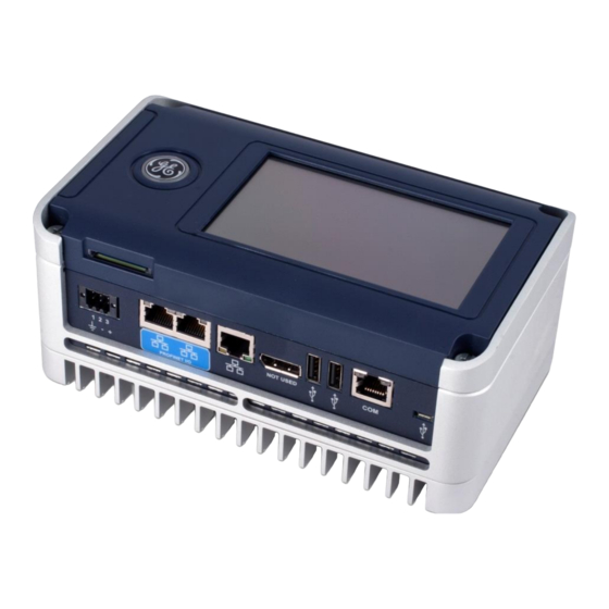
Chapter 1. Introduction RXi Controller User Features 1.3.1 Indicator and Port Locations 1.3.2 Status LED Operation LED State RXi Controller State Blue, blinking Power on Green, blinking Operating system initialization complete/Jump to Application Blue, solid Stop mode Green, solid Run mode Red, solid Stop Fault Red, steady blink... -
Page 20: Profinet And Gbe Port Leds
Chapter 1. Introduction 1.3.3 PROFINET and GbE Port LEDs Each port has two LED indicators, ACTIVITY and LINK. LED State Operating State ACTIVITY LINK ACTIVITY Blinking, Amber 10/100/1000 activity LINK On, Green Gigabit link status GFK-2816F August 2015... -
Page 21: Additional Information
For additional information, refer to the manuals listed below. Manuals can be downloaded from the Support website. Proficy Machine Edition Logic Developer Getting Started Manual GFK-1918 PACSystems RXi Energy Pack ICRXIACCEPK01A Quick Start Guide GFK-2835 PACSystems Controllers: Battery and Energy Pack Manual GFK-2741 PACSystems RX7i and RX3i CPU Programmer’s Reference Manual... -
Page 22: Revisions In This Manual
Chapter 1. Introduction Revisions in this Manual Note: A given feature may not be implemented on all versions of the RXi Controller. To determine whether a feature is available on a given CPU model and firmware version, please refer to the Important Product Information (IPI) document provided for the CPU version that you are using. - Page 23 Chapter 1. Introduction PACSystems* RXi Distributed IO Controller User Manual GFK-2816F...
-
Page 24: Chapter 2 Installation
(ground). (Refer to Section 2.4.2 Connecting the RXi Controller Directly to 24Vdc Input Power. ■ If you are using an Energy Pack, refer to the PACSystems RXi Energy Pack ICRXIACCEPK01A Quick Start Guide, GFK-2835 for grounding information. ■... -
Page 25: Mounting Orientation
Chapter 2. Installation Panel Central Earth Ground Point Ground Ground Wiring Example 2.2.2 Mounting Orientation The cooling fins on the back of the controller must be vertical. Correct Power and communications port connections Incorrect PACSystems* RXi Distributed IO Controller User Manual GFK-2816F... -
Page 26: Dimensions And Clearances For Installation
Chapter 2. Installation 2.2.3 Dimensions and Clearances for Installation Dimensions RXi Controller: 191.8 mm x 115.6 mm x 81.3 mm (7.55 in x 4.55 in. x 3.2 in) Backplate: 226 mm x 137 mm x 12 mm (8.90 in. x 5.39 in. x 0.47 in.) Minimum clearances for heat Each side: 51mm (2 inches) dissipation... -
Page 27: Mounting Procedures
Chapter 2. Installation Mounting Procedures The RXi Controller has four captive machine screws in its base for attaching the unit to the Backplate or panel. Note: Before selecting a mounting method, refer to the thermal requirements in Section 1.1.3 RXi Controller Environmental Specifications. 2.3.1 Mounting the RXi Controller Directly on a Panel You will need the following:... -
Page 28: Mounting The Rxi Controller On A Din Rail
Chapter 2. Installation 2.3.2 Mounting the RXi Controller on a DIN Rail You will need the following: ■ One 2.5mm hex driver (included with the RXi Controller) ■ One flathead or large Phillips screwdriver ■ One Backplate, ICRXIACCBPL When installed on the Backplate, the controller mounts to a standard EN 50022 DIN rail with the following dimensions. - Page 29 Chapter 2. Installation 2. Install the unit on the DIN Rail. a. Start with the unit rotated approximately 20º from the panel. b. Engage the latches at either the top or bottom of the black DIN rail clip (attached to the adaptor) onto the DIN rail.
-
Page 30: Mounting The Rxi Controller On A Panel Using A Backplate
Chapter 2. Installation 2.3.3 Mounting the RXi Controller on a Panel Using a Backplate When mounting the Controller/Backplate assembly on the panel, you can insert the screws from the front of the Backplate or from the back of the panel You will need the following: ■... -
Page 31: Installing The Idm On The Rxi Controller
Place the IDM on the RXi and use a flathead or large Phillips screwdriver to hand-tighten the four captive screws. 2.3.5 Installing the Energy Pack To install the ICRXIACCEPK01A Energy Pack, refer to the PACSystems RXi Energy Pack ICRXIACCEPK01A Quick Start Guide, GFK-2835. PACSystems* RXi Distributed IO Controller User Manual GFK-2816F... -
Page 32: Connectors And Cabling
Shielded cable required for 1 Gbps operation. 2.4.1 Connecting Input Power using the Energy Pack To connect power to the Controller through the Energy Pack, refer to the PACSystems RXi Energy Pack ICRXIACCEPK01A Quick Start Guide, GFK-2835. 2.4.2 Connecting the RXi Controller Directly to 24Vdc Input Power... -
Page 33: Connecting To The Gbe Port
Chapter 2. Installation A small screwdriver (such as a 1.4 mm flat-head jeweler’s screwdriver) ■ Using the power cord, attach the power supply to the power terminal block. To insert the wires in the power terminal block connector, you may need to use a small screwdriver to release the spring clamp on the terminal block. - Page 34 Chapter 2. Installation Ethernet Media The RXi Controller can operate directly on 10Base-T, 100Base-TX or 1000Base-T media via its network port. All three arrangements can use up to 100m of twisted pair cable between each node and a switch, hub, or repeater. Note: For all three types, shielded twisted pair (STP) cable is required to maintain CE compliance.
-
Page 35: Connecting To A Profinet Network
Chapter 2. Installation 2.4.4 Connecting to a PROFINET Network The RXi Controller provides two RJ-45 ports for PROFINET network connections. They can also be used for general Ethernet communications on a 10BaseT, 100BaseTX, or 1000BaseT IEEE 802.3 network. PROFINET IO can be connected to either of the two PROFINET ports. Use of Media Redundancy Protocol (MRP) requires both PROFINET ports. -
Page 36: Sd (Secure Digital) Card Slot
Chapter 2. Installation 2.4.8 SD (Secure Digital) Card Slot Not implemented 2.4.9 DISPLAY PORT Not implemented GFK-2816F August 2015... -
Page 37: Replacing The Rtc Battery
Chapter 2. Installation Replacing the RTC Battery The real-time clock is backed up by a lithium coin cell battery, IC690ACC001, which has an estimated life of 5 years and must be replaced every 5 years on a regular maintenance schedule. There are no diagnostics or indicators that monitor RTC battery status. If the RTC battery fails, the CPU date and time is reset to 12:00 AM, 01-01-2008 at startup. - Page 38 Chapter 2. Installation 1. Remove power from the RXi Controller. 2. Loosen the four captive screws on the Display Module and remove it. 3. Remove the inner lid from the RXi Controller. 4. Remove the RTC battery from the retaining clip, being careful to not bend the positive terminal clip.
- Page 39 Chapter 2. Installation PACSystems* RXi Distributed IO Controller User Manual GFK-2816F...
-
Page 40: Chapter 3 Getting Started: Initial Power-Up And Configuration
Power supply and power cord. Refer to Section 2.4.2, Connecting the RXi Controller Directly to 24Vdc Input Power for requirements. Energy Pack kit, ICRXIACCEPK01A. Refer to the PACSystems RXi Energy Pack ICRXIACCEPK01A Quick Start Guide, GFK-2835 for installation and operation. -
Page 41: Connecting Input Power And The Gbe Cable
Chapter 3. Getting Started: Initial Power-up and Configuration Connecting Input Power and the GbE Cable 1. Connect input power as described in Section 2.4.2, Connecting the RXi Controller Directly to 24Vdc Input Power. 2. Connect the PC running Proficy Machine Edition software to the GbE port as described in Section 2.4.3, Connecting to the GbE Port. -
Page 42: Establishing Programmer Communications With The Unit And Downloading A Project
Chapter 3. Getting Started: Initial Power-up and Configuration Establishing Programmer Communications with the Unit and Downloading a Project 1. Set the IP Address on the RXi. Caution The Ethernet interface must be configured with the correct IP Address for proper operation in a TCP/IP Ethernet network. - Page 43 Chapter 3. Getting Started: Initial Power-up and Configuration 2. Go online with Proficy Machine Edition software. In Proficy Machine Edition, create a project with a PACSystems RXi target. In the Inspector, set the active target’s IP Address property to the address of the RXi.
-
Page 44: Configuring The Embedded Profinet Io-Controller And Its Io Devices On A Profinet Network
Basic configuration steps for a PROFINET network: Configure the PROFINET IO-Controller parameters and properties in the Proficy Machine Edition hardware configuration tool. Add IO-Devices to the PROFINET network. These can be GE Intelligent Platforms PROFINET Scanner (PNS) modules or third-party IO-Devices. Configure the IO-Devices. -
Page 45: Intelligent Display Module (Idm) - Basic Operations
Chapter 3. Getting Started: Initial Power-up and Configuration Intelligent Display Module (IDM) - Basic Operations Although Proficy Machine Edition is required to create and download configuration and logic to the RXi, you can perform many operations with the IDM. These include setting an initial IP address, starting or stopping the RXi, and viewing and clearing fault tables. -
Page 46: Idm Operational Notes
Chapter 3. Getting Started: Initial Power-up and Configuration IDM Operational Notes ■ The IDM communicates through an internal Ethernet connection using the SRTP protocol. No more than 47 user SRTP connections should be established to the controller, so that a connection is available for the IDM. ■... - Page 47 Chapter 3. Getting Started: Initial Power-up and Configuration PACSystems* RXi Distributed IO Controller User Manual GFK-2816F...
-
Page 48: Chapter 4 Configuration
Chapter 4. Configuration Chapter 4 Configuration The PACSystems RXi Controller and PROFINET I/O system is configured using Proficy Machine Edition Logic Developer-PLC programming software. Refer to the Proficy Machine Edition Logic Developer Getting Started Manual, GFK-1918 and the online help for a description of configuration functions. -
Page 49: Configuring Controller Operation
To configure the RXi Controller’s embedded CPU functionality using the Proficy Machine Edition Logic Developer-PLC programming software: 1. In the Project tab of the Navigator, expand your PACSystems RXi target and the hardware configuration. 2. Right click the Controller and choose Configure. The Parameter Editor window displays the CPU parameters. -
Page 50: Controller Settings Parameters
Standard Modbus Addressing: Causes the Ethernet firmware to use the standard map, which is displayed on the Modbus TCP Address Map tab. Default: Disabled For details on the PACSystems RXi implementation of Modbus TCP server, refer to Section 8.5, Modbus TCP Server Operation. GFK-2816F... -
Page 51: Controller Scan Parameters
Chapter 4. Configuration 4.1.2 Controller Scan Parameters These parameters determine the characteristics of CPU sweep execution. Scan Parameters Sweep Mode The sweep mode determines the priority of tasks the CPU performs during the sweep and defines how much time is allotted to each task. The parameters that can be modified vary depending on the selection for sweep mode. - Page 52 Chapter 4. Configuration Scan Parameters Controller (Available only when Sweep Mode is set to Normal. Read-only if the Controller Communications Communications Window Mode is set to Complete.) The maximum execution time for the Window Timer (ms) Controller Communications Window per scan. This value cannot be greater than the value for the watchdog timer.
- Page 53 Choices: 0, 1, 2, 3, 4, 5. Defaults: ▪ 0 when creating a new PACSystems RXi target or converting a Series 90-70 target to RXi. ▪ 1 when converting a Series 90-30 target to RXi. PACSystems* RXi Distributed IO Controller User Manual...
-
Page 54: Controller Memory Parameters
Chapter 4. Configuration Using the IDM to select Sweep modes and Communications Window Values You can use the IDM to change the CPU sweep mode and values for the communications windows as follows: To access additional screens, touch the Next button. Note: additional information related to IDM operation, refer to Section 3.6, IDM Operational Notes. - Page 55 Chapter 4. Configuration Calculation of Memory Required for Managed Memory The total number of bytes required for symbolic and I/O variables is calculated as follows: [((number of symbolic discrete bits) × 3) / (8 bits/byte)] [((number of I/O discrete bits) × Md) / (8 bits/byte)] [(number of symbolic words ×...
- Page 56 Chapter 4. Configuration Memory Allocation Configuration Memory Parameters Reference Points %I Discrete Input, %Q Discrete Output, The upper range for each of these memory types. Read only. %M Internal Discrete, %S System, %SA System, %SB System, %SC System, %T Temporary Status, %G Genius Global Total Reference Points Read only.
-
Page 57: Fault Parameters
Chapter 4. Configuration 4.1.4 Fault Parameters You can configure each fault action to be either diagnostic or fatal. A diagnostic fault does not stop the Controller from executing logic. It sets a diagnostic variable and is logged in a fault table. A fatal fault transitions the Controller to the Stop Faulted mode. -
Page 58: Modbus Tcp Address Map
Chapter 4. Configuration 4.1.6 Modbus TCP Address Map This read-only tab displays the standard mapping assignments between Modbus address space and the CPU address space. Ethernet interfaces in the PACSystems controller use Modbus-to-Controller address mapping based on this map. Modbus Register The Modbus protocol uses five reference table designations: 0xxxx Coil Table. -
Page 59: Access Control
Chapter 4. Configuration 4.1.7 Access Control The Access Control list allows you to specify the reference address ranges that can be accessed by non-local devices such as HMIs and other controllers. To use this feature, Enhanced Security must be enabled in the target’s properties. When Enhanced Security mode is enabled, any reference address range not defined cannot be accessed by other devices. -
Page 60: Configuring The Embedded Profinet Io-Controller (Pnc)
Chapter 4. Configuration Configuring the Embedded PROFINET IO-Controller (PNC) This section explains how to configure the RXi PNC and its IO-devices in a PACSystems RXi Controller system. The Proficy Machine Edition programming software is used to create and download the configuration for an RXi PROFINET network and its devices. -
Page 61: Basic Configuration Steps
Configure the parameters of the PNC. ■ Select the PNC and add IO-Devices to its LAN. These IO-Devices can be GE Intelligent Platforms PNS modules or third-party IO-Devices. PNS modules and third-party IO-Devices use GSDML files to describe their capabilities. Proficy Machine Edition imports these GSDML files and incorporates the devices into the configuration. - Page 62 Chapter 4. Configuration 3. Edit the PNC’s parameters and its communications properties as described in this chapter. Exploring PROFINET Networks To explore the PROFINET networks in the system while PROFICY Machine Edition is online with the RXi system, right-click on the Target icon (not the PNC) and select Explore PROFINET Networks under the Online Commands menu item.
- Page 63 Chapter 4. Configuration Viewing the PROFINET IO-Controller’s LAN To view the LANs in the project, click Tools in the PROFICY Machine Edition toolbar, and select LAN View, or right-click the PNC and select Manage LANs. Adding the first RXi target to the project automatically creates a LAN for it. For each subsequent RXi target, an existing LAN can be selected or a new LAN can be created.
- Page 64 Chapter 4. Configuration Media Redundancy Tab By default, a PNC is not set up for Media Redundancy. If the system will use Media Redundancy (refer to Chapter 11, PROFINET Redundant Media for more information), open the Media Redundancy Tab and select either Client or Manager: If the PNC will be a Media Redundancy Client, click on Ring Port 1 and Ring Port 2 to choose the module ports then select the Domain Name that will be used.
- Page 65 Chapter 4. Configuration Terminals Tab This configuration tab is displayed only when the PROFINET IO-Controller’s Variable Mode property is set to True. When Variable Mode is selected, the Status bits are referenced as I/O variables that are mapped to the status bits on this configuration tab. The use of I/O variables allows you to configure the PNC without having to specify the reference addresses to use for the status information.
- Page 66 Chapter 4. Configuration Non-Volatile Configuration Parameters and Properties for PNC These values are updated the first time a hardware configuration is stored to the RXi. They are not reset to the default values when configuration is cleared; they can only change when a new hardware configuration is stored.
-
Page 67: Configuring Profinet Lans
Chapter 4. Configuration 4.2.4 Configuring PROFINET LANs To view the LANs in the project, click on Tools in the Machine Edition toolbar, and select LAN View from the menu. Expand the LAN icon in the LAN View to see the devices it includes. Configuring the LAN Properties Machine Edition automatically assigns a set of default properties to the LAN. - Page 68 Chapter 4. Configuration Subnet Mask: Mechanism that filters network communications so that they are routed only to subnets to which they are addressed. The value defined here propagates to PNCs and I/O devices throughout the network. Caution If the subnet mask is improperly set, devices may be unable to communicate on the network and might disrupt network communications.
-
Page 69: Adding A Ge Intelligent Platforms Profinet Scanner To A Lan
Chapter 4. Configuration 4.2.5 Adding a GE Intelligent Platforms PROFINET Scanner to a LAN To add a PROFINET Scanner (PNS) to a LAN, in the Navigator, right-click the PNC and select Add IO-Device. The PROFINET Device Catalog, which is populated by the GSDML files installed with Proficy Machine Edition, appears. - Page 70 Chapter 4. Configuration Configuring a PROFINET Scanner After adding a PNS to the LAN, its parameters can be configured by either double-clicking the scanner in the Navigator, or right-clicking and selecting Configure from the menu. PROFINET Scanner Parameters The parameters displayed will depend on the type of PNS. For configuration details, refer to the user manual for the PNS.
- Page 71 Chapter 4. Configuration Adding Modules to a Remote Node To add a module to the remote node, right click on the PNS icon in the Navigator and select Change Module List. In the right pane of the Change Module List window, expand the list of module types.
- Page 73 Chapter 4. Configuration Editing Third-Party IO-Device Parameters To configure a third-party IO-Device’s parameters, either double-click on the module in the Navigator, or right-click on the module and select Configure from the menu. Upon opening the IO-Devices configuration, you will see an IO-Device Access Point tab, a GSDML Details tab, and possibly additional parameter tabs (if defined by the device manufacturer in the associated GSDML file).
- Page 74 Chapter 4. Configuration If the IO-Device will be a Media Redundancy Manager, you can edit the Ring Port selections as above. The device’s GSDML file determines the valid ranges for Default Test Interval and Test Monitoring Count. For the Media Redundancy Manager, the Domain Name can be edited by typing over the default name.
- Page 75 Chapter 4. Configuration Configuring Sub-Modules of a Third-Party IO-Device To configure the sub-modules of a third-party IO-Device, expand it in the Navigator. For example: This example’s device is a switch. The parameters of its ports can be viewed and edited by either double-clicking on a port, or selecting a port then right-clicking and selecting Configure from the menu.
-
Page 76: Viewing / Editing Io-Device Properties
Chapter 4. Configuration Sub-Module Parameters (GSDML Tab) The GSDML tab displays the device’s GSDML parameters, which cannot be edited. 4.2.7 Viewing / Editing IO-Device Properties In addition to the parameter configuration described on the previous pages, all IO-Devices (PNS modules and third-party devices) have other configurable properties. These properties are displayed in the Proficy Machine Edition Inspector pane when the device is selected in the Navigator. - Page 77 Chapter 4. Configuration Note: Because the update rate affects loading on the PNC, the maximum number of devices (up to 128) is limited to the equivalent of eight devices with 1ms update rates. For additional information, refer to PNC Loading Limits on page 47. Reference Variable: To be used by the PNIO_DEV_COMM logic blocks.
-
Page 78: Assigning Io-Device Names
Chapter 4. Configuration 4.2.8 Assigning IO-Device Names After the PNS and third-party IO-Devices on the LAN have been entered into the configuration, the Discovery and Configuration Protocol (DCP) tool in Proficy Machine Edition must be used to assign a name to each IO-Device. This step is required before downloading the configuration from the PNC, or the PNC will be unable to connect to the devices and deliver their configuration. - Page 79 Chapter 4. Configuration If the name of the device on the network is not correct, you must update the device name. To do this, select the device in the list of devices and click Edit Device. This will open a new dialog that can be used to set various parameters, including device name, directly on the device.
-
Page 80: After The Configuration Is Stored To The Rxi Cpu
Chapter 4. Configuration 4.2.9 After the Configuration is Stored to the RXi CPU If the configuration is stored to non-volatile memory or if the Energy Pack is present, the RXi Controller maintains configuration data over a power cycle. The PNC transfers the configuration for remote IO-Devices over the PROFINET network. PROFINET delivers IO-Device configurations when the IO-Controller establishes an Application Relationship (AR) with the IO-Device. -
Page 81: Configuring The Embedded Ethernet Interface
Chapter 4. Configuration Configuring the Embedded Ethernet Interface Before you can use the embedded Ethernet Interface, you must configure it using the programming software. Ethernet interface configuration includes the following procedures: ▪ Using the IDM to assign a temporary IP address (page 29) for initial network operation, such as connecting the programmer to download the hardware configuration. -
Page 82: Pinging Tcp/Ip Ethernet Interfaces On The Network
Chapter 4. Configuration Note: If the isolated network is connected to another network, the IP addresses 10.0.0.1 through 10.0.0.255 must not be used and the subnet mask, and gateway IP address must be assigned by the network administrator. The IP addresses must be assigned so that they are compatible with the connected network. -
Page 83: Storing (Downloading) Hardware Configuration
Chapter 4. Configuration Storing (Downloading) Hardware Configuration A PACSystems control system is configured by creating a configuration file in the programming software, then transferring (downloading) the file from the programmer to the controller. The CPU stores the configuration file in its non-volatile memory. After the configuration is stored, I/O scanning is enabled or disabled according to the newly stored configuration parameter, Stop-Mode I/O. -
Page 84: Chapter 5 Cpu Operation
Chapter 5. CPU Operation Chapter 5 CPU Operation This chapter describes the operating modes of a PACSystems RXi CPU and describes the tasks the CPU carries out during these modes. The following topics are discussed: ■ CPU Sweep ■ Program Scheduling Modes ■... -
Page 85: Cpu Sweep
Chapter 5. CPU Operation CPU Sweep The application program in the CPU executes repeatedly until stopped by a command from the programmer, from another device, from the Intelligent Display Module, or a fatal fault occurs. In addition to executing the application program, the CPU obtains data from input devices, sends data to output devices, performs internal housekeeping, performs communications tasks, and performs self-tests. -
Page 86: Parts Of The Cpu Sweep
Chapter 5. CPU Operation 5.1.1 Parts of the CPU Sweep The major phases in a typical CPU sweep are shown in the figure below and explained in the table following. Parts of a Typical CPU Sweep GFK-2816F August 2015... - Page 87 Chapter 5. CPU Operation Major Phases in a Typical CPU Sweep Phase Activity Housekeeping The housekeeping portion of the sweep performs the tasks necessary to prepare for the start of the sweep. This includes updating %S bits, determining timer update values and determining the mode of the sweep (Stop or Run.
-
Page 88: Cpu Sweep Modes
Chapter 5. CPU Operation 5.1.2 CPU Sweep Modes Normal Sweep Mode In Normal Sweep mode, each sweep can consume a variable amount of time. The Logic window is executed in its entirety each sweep. The Communications window can be set to execute in a Limited or Run-to-Completion mode. - Page 89 Chapter 5. CPU Operation Constant Sweep Mode In Constant Sweep mode, each sweep begins at a specified Constant Sweep time after the previous sweep began. The Logic Window is executed in its entirety each sweep. If there is sufficient time at the end of the sweep, the CPU alternates among the Controller Communications, Backplane Communications, and Background windows, allowing them to execute until it is time for the next sweep to begin.
- Page 90 Chapter 5. CPU Operation Constant Window Mode In Constant Window mode, each sweep can consume a variable amount of time. The Logic Window is executed in its entirety each sweep. The CPU alternates among the three windows, allowing them execute for a time equal to the value set for the Constant Window timer.
-
Page 91: Program Scheduling Modes
Chapter 5. CPU Operation Program Scheduling Modes The CPU supports one program scheduling mode, the Ordered mode. An ordered program is executed in its entirety once per sweep in the Logic Window. Window Modes The previous section describes the phases of a typical CPU sweep. The Controller Communications, Backplane Communications, and Background windows can be run in various modes, based on the CPU sweep mode. -
Page 92: Data Coherency In Communications Windows
Chapter 5. CPU Operation Data Coherency in Communications Windows When running in Constant or Limited Window mode, the Controller and Backplane Communications Windows may be terminated early in all CPU sweep modes. If an external device, such as CIMPLICITY HMI, is transferring a block of data, the coherency of the data block may be disrupted if the communications window is terminated prior to completing the request. -
Page 93: Run/Stop Operations
Chapter 5. CPU Operation Run/Stop Operations The PACSystems CPUs support four run/stop modes of operation. You can change these modes in the following ways: configuration from the programming software, LD function blocks, and system calls from C applications. Switching to and from various modes can be restricted based on privilege levels, passwords, etc. -
Page 94: Cpu Stop Modes
Chapter 5. CPU Operation 5.5.1 CPU Stop Modes The CPU has two modes of operation while it is in Stop mode: ■ I/O Scan Enabled - the Input and Output scans are performed each sweep ■ I/O Scan Disabled - the Input and Output scans are skipped When the CPU is in Stop mode, it does not execute the application program. -
Page 95: Stop-To-Run Mode Transition
Chapter 5. CPU Operation 5.5.2 Stop-to-Run Mode Transition The CPU performs the following operations on Stop-to-Run transition: ■ Validation of sweep mode and program scheduling mode selections ■ Validation of references used by programs with the actual configured sizes ■ Re-initialization of data areas for external blocks and standalone C programs ■... -
Page 96: Flash Memory Operation
Chapter 5. CPU Operation Flash Memory Operation The CPU stores the current configuration and application in user memory. You can also store this data into non-volatile flash memory. The PACSystems CPU provides enough flash memory to hold all of user space, all reference tables that aren't counted against user space, and any overhead required. -
Page 97: Logic/Configuration Source And Cpu Operating Mode At Power-Up
Chapter 5. CPU Operation Logic/Configuration Source and CPU Operating Mode at Power-up Flash and user memory can contain different values for the Logic/Configuration Power-up Source parameter. The following tables summarize how these settings determine the logic/configuration source after a power cycle. CPU mode is affected by the Power-up Mode and Stop-Mode I/O Scanning parameters, and the power down mode as shown in the tables on page 85. - Page 98 Chapter 5. CPU Operation CPU Mode when Memory is not Preserved and Power-up Source is Flash Configured CPU Mode Power-up Mode Run Enabled Stop Stop Disabled Last Run Disabled CPU Mode when Memory is Preserved Configuration Parameters Power Down Mode CPU Mode Power-up Mode Stop-Mode I/O Scanning Run Enabled...
-
Page 99: Clocks And Timers
Chapter 5. CPU Operation Clocks and Timers Clocks and timers provided by the CPU include an elapsed time clock, a time-of-day clock, and software and hardware watchdog timers. For information on timer instructions provided by the CPU instruction set, refer to the Proficy Machine Edition online help. -
Page 100: Watchdog Timers
Chapter 5. CPU Operation 5.8.3 Watchdog Timers Software Watchdog Timer A software watchdog timer in the CPU is designed to detect failure to complete sweep conditions. The timer value for the software watchdog timer is set using the programming software. The allowable range for this timer is 10 to 2550 ms; the default value is 200 ms. The software watchdog timer always starts from zero at the beginning of each sweep. -
Page 101: Timed Contacts
Chapter 5. CPU Operation To recover from Stop-Halt mode and return to normal operation, all non-volatile memory must be cleared. This can be done by disconnecting the Energy Pack and power cycling the unit. If power cycled with the Energy Pack connected, the CPU returns to Stop-Halt mode and retains all non-volatile memory, including fault tables. -
Page 102: System Security
Chapter 5. CPU Operation System Security The PACSystems CPU supports the following two types of system security: ■ Passwords/privilege levels ■ OEM protection With firmware releases 7.80 and later, RXi Controller provides full support for Enhanced Security Passwords, which provides a more secure mechanism for setting and authenticating passwords and OEM keys. -
Page 103: Oem Protection - Legacy Mode
Chapter 5. CPU Operation Protection Level Request from Programmer In Legacy mode, upon connection to the CPU, the programmer requests the CPU to move to the highest unprotected level. The programmer requests a privilege level change by supplying the new privilege level and the password for that level. -
Page 104: Enhanced Security For Passwords And Oem Protection
Chapter 5. CPU Operation 5.9.3 Enhanced Security for Passwords and OEM Protection Enhanced Security passwords provide a cryptographically secure password protocol between an SRTP client (for example Proficy Machine Edition) and a PACSystems controller. Enhanced Security passwords operate very similar to the Legacy security password operation that is supported by previous firmware releases. -
Page 105: Legacy/Enhanced Security Comparison
Chapter 5. CPU Operation 5.9.4 Legacy/Enhanced Security Comparison Feature Legacy (less secure) Enhanced (more secure) Level 2, 3 and 4 protection Levels 2, 3 and 4 must be set Passwords can be set or modified simultaneously. (If individually or in a group. When you only want to change one, changing passwords, the old you must enter all three.) -
Page 106: Pacsystems I/O System
Chapter 5. CPU Operation PACSystems I/O System 5.10 The embedded PNC provides the interface between the CPU and other devices. For details, refer to Section 10.7, RXi CPU Operations for PROFINET. 5.10.1 I/O System Diagnostic Data Collection Diagnostic data in a PACSystems I/O system is obtained via diagnostic bits sent from the I/O modules to their PROFINET scanners. -
Page 107: Power-Up And Power-Down Sequences
Chapter 5. CPU Operation Power-Up and Power-Down Sequences 5.11 Note: To ensure user memory backup, an operational Energy Pack must be attached at the moment of power-down and at power recovery. 5.11.1 Power-Up Sequence System power-up consists of the following parts: ■... -
Page 108: Retention Of Data Memory Across Power Failure
Chapter 5. CPU Operation 5.11.3 Retention of Data Memory across Power Failure The following types of data are preserved across a power cycle with an operational Energy Pack: ■ Application program ■ Fault tables and other diagnostic data ■ Checksums on programs and blocks ■... - Page 109 Chapter 5. CPU Operation PACSystems* RXi Distributed IO Controller User Manual GFK-2816F...
-
Page 110: Chapter 6 Program Organization
Chapter 6. Program Organization Chapter 6 Program Organization This chapter provides information about the operation of application programs in a PACSystems CPU. ■ Structure of the Application Program ■ Controlling Program Execution ■ Interrupt-Driven Blocks GFK-2816F August 2015... -
Page 111: Structure Of A Pacsystems Application Program
Chapter 6. Program Organization Structure of a PACSystems Application Program A PACSystems application consists of one block-structured application program. The application program contains all the logic needed to control the operations of the CPU and the modules in the system. Application programs are created using the programming software and transferred to the CPU. -
Page 112: Nested Calls
Chapter 6. Program Organization Edition online help. 6.1.4 Nested Calls The CPU allows nested block calls as long as there is enough execution stack space to support the call. If there is not enough stack space to support a given block call, an Application Stack Overflow fault is logged. - Page 113 Chapter 6. Program Organization Program Blocks Any block can be a program block. The _MAIN block is automatically declared when you create a block-structured program. When you declare any other block, you must assign it a unique block name. A block is automatically configured with no input parameters and one output parameter (OK).
- Page 114 Chapter 6. Program Organization Parameterized Blocks Any block except _MAIN can be a parameterized block. When you declare a parameterized block, you must assign it a unique block name. A parameterized block can be configured with up to 63 input and 64 output parameters. A parameterized block executes when called from the program logic in the _MAIN block, another block, or itself.
- Page 115 Chapter 6. Program Organization Using Parameters with a Parameterized Block A parameterized block may be defined to have between 0 and 63 formal input parameters, and between 1 and 64 formal output parameters. A ‘power-flow out’ (or OK) parameter, named Y0, is automatically defined for every parameterized block. It is a BOOL parameter of LENGTH 1, and indicates the successful execution of the parameterized block.
- Page 116 Chapter 6. Program Organization Arguments or actual parameters are passed into a parameterized block when a parameterized block call is executed. In general, arguments to formal parameters may come from any memory type, may be data flow, and may be constants (when the formal parameter’s LENGTH is 1).
- Page 117 Chapter 6. Program Organization User Defined Function Blocks Users can define their own blocks, which have parameters and instance data, instead of being limited to the standard and built-in function blocks provided in the PACSystems instruction set. In many cases, the use of this feature results in a reduction in total program size.
- Page 118 Chapter 6. Program Organization Creating UDFB Instances You create an instance of a UDFB by calling it in your logic and assigning an instance name in the function properties. In the following LD example, the first rung creates two instances of the UDFB, Motors. The instance variables associated with the instances are motors.motor1 and motors.motor2.
- Page 119 Chapter 6. Program Organization Using Parameters with UDFBs UDFBs support up to 63 inputs and up to 64 outputs. Each UDFB has a predefined Boolean output parameter, Y0, which the CPU sets to true upon each invocation of the block. Y0 can be controlled by logic within the block and provides the output status of the block.
- Page 120 Chapter 6. Program Organization Using Internal Member Variables with UDFBs A UDFB can have any number of internal member variables. Internal variables’ values are not passed through the input and output parameters. An internal variable cannot have the same name as a parameter of the UDFB it is defined in. An internal variable can be: ■...
- Page 121 Chapter 6. Program Organization UDFB Operation with Other Blocks A UDFB instance that is of global scope can be invoked by another UDFB’s logic or any other block’s logic. A UDFB instance that is passed (by reference) as an argument to a UDFB can be invoked by the UDFB’s logic.
- Page 122 Chapter 6. Program Organization Using Parameters With an External Block An external block may be defined to have between zero and 63 formal input parameters and between one and 64 formal output parameters. A ‘power-flow out’ (or OK) parameter, named Y0, is automatically defined for every external block.
-
Page 123: Local Data
Chapter 6. Program Organization 6.1.6 Local Data Each block or UDFB in a block-structured program has an associated local data block. _MAIN’s data block memory is referenced by %P; all other data block memories are referenced by %L. The size of the data block is dependent on the highest reference in its block for %L and in all blocks for %P. -
Page 124: Parameter Passing Mechanisms
Chapter 6. Program Organization 6.1.7 Parameter Passing Mechanisms All blocks (except _MAIN) have at least one parameter and thus are affected by parameter passing mechanisms. A parameter passing mechanism describes the way that data is passed from an argument in a calling block to a parameter in the called block, and from the parameter in the called block back to the argument in the calling block. -
Page 125: Languages
Chapter 6. Program Organization When a parameter is passed by value (UDFB inputs only), the value of its argument is copied into a local stack memory associated with the called block. All logic within the called block that reads or writes to the parameter is reading or writing to this stack memory. - Page 126 Chapter 6. Program Organization LIFORD_INT ABS_INT Data Move Timers LIFORD_DINT ABS_DINT BLKCLR ONDTR LIFOWRT_INT ABS_REAL BITSEQ OFDT LIFOWRT_DINT ABS_LREAL MOVE_BIT LIFOWRT_DWORD SCALE_INT MOVE_DINT SCALE_DINT MOVE_INT SCALE_UINT MOVE_UINT Array SQRT_INT MOVE_WORD ARRAY_MOVE_BIT SQRT_DINT MOVE_DWORD ARRAY_MOVE_BYTE Counters SQRT_REAL MOVE_REAL ARRAY_MOVE_WORD UPCTR SQRT_LREAL MOVE_LREAL ARRAY_MOVE_DWORD DNCTR...
- Page 127 Chapter 6. Program Organization Service Requests (SVC_REQ) 1,Change/read constant sweep timer 2,Read window modes and time values 3,Change controller communications window mode and timer value 4,Change backplane communications window mode and timer value 5,Change background task window mode and timer value 6,Change/read number of words to checksum 7,Read or change the...
-
Page 128: Controlling Program Execution
Chapter 6. Program Organization Controlling Program Execution There are many ways in which program execution can be controlled to meet the system’s timing requirements. The PACSystems CPU instruction set contains several powerful control functions that can be included in an application program to limit or change the way the CPU executes the program and scans I/O. -
Page 129: Interrupt-Driven Blocks
Chapter 6. Program Organization Interrupt-Driven Blocks Timed interrupts can be used to start a block’s execution. These interrupts are generated by the CPU based on a user-specified time interval with an initial delay (if specified) applied on Stop-to-Run transition of the CPU. Caution Interrupt-driven block execution can interrupt the execution of non-interrupt-driven logic. -
Page 130: Configuring Timed Interrupts
Chapter 6. Program Organization Note: We strongly recommend that interrupt-driven blocks not be called from the _MAIN block or other non-interrupt driven blocks because the interrupt and non-interrupt driven blocks could be reading and writing the same global memories at indeterminate times relative to each other. - Page 131 Chapter 6. Program Organization activities. Execution of the normal CPU sweep activities is resumed after the interrupt-driven block execution completes. If the CPU receives one or more interrupts while executing an interrupt block, it places the incoming interrupts into the queue while it finishes executing the current interrupt block. If an interrupt driven block is already in the queue, additional interrupts that occur for this block are ignored.
-
Page 132: Chapter 7 Cpu Program Data
Chapter 7. CPU Program Data Chapter 7 CPU Program Data This chapter describes the types of data that can be used in an application program, and explains how that data is stored in the PACSystems CPU’s memory. ■ Variables ■ Reference Memory ■... -
Page 133: Variables
Chapter 7. CPU Program Data Variables A variable is a named storage space for data values. It represents a memory location in the target PACSystems CPU. A variable can be mapped to a reference address (for example, %R00001). If you do not map a variable to a specific reference address, it is considered a symbolic variable. -
Page 134: I/O Variables
Chapter 7. CPU Program Data ■ Arrays of the following data types are not supported: Arrays of user defined function block (UDFB) instance variables. Arrays of TON, TOF, or TP instance variables. Arrays of reference ID variables (RIVs) that contain one or more linked RIV elements. Note: A RIV array is supported when none of its elements is linked. - Page 135 Chapter 7. CPU Program Data Restrictions on the Use of I/O Variables ■ Since I/O variables are a form of symbolic variable, the same restrictions that apply to other symbolic variables of the same data type and array bounds apply to I/O variables. ■...
-
Page 136: Arrays
Chapter 7. CPU Program Data 7.1.4 Arrays An array is a complex data type composed of a series of variable elements with identical data types. Any variable can become an array, except for another array, a variable element, or a UDFB. - Page 137 Chapter 7. CPU Program Data An index variable can be one of the following: Symbolic variable I/O variable Variable mapped to % memory areas such as %R Structure element Array element with a constant index ...
-
Page 138: Ensuring That A Variable Index Does Not Exceed The Upper Boundary Of An Array
Chapter 7. CPU Program Data The following do not support array elements with variable indexes: Indirect references Reference ID variables (RIVs) and I/O variables when accessed in the Hardware Configuration Note: In logic, RIVs and I/O variables support variable indexes. ... -
Page 139: Reference Memory
Chapter 7. CPU Program Data Reference Memory The CPU stores program data in bit memory and word memory. Both types of memory are divided into different types with specific characteristics. By convention, each type is normally used for a specific type of data, as explained below. However, there is great flexibility in actual memory assignment. - Page 140 Chapter 7. CPU Program Data Bit in Word References Bit in word referencing allows you to specify individual bits in a word reference type as inputs and outputs of Boolean expressions, functions, and calls that accept bit parameters (such as parameterized blocks).
-
Page 141: Bit (Discrete) References
Chapter 7. CPU Program Data 7.2.2 Bit (Discrete) References Type Description Represents input references. %I references are located in the input status table, which stores the state of all inputs received from input modules during the last input scan. A reference address is assigned to discrete input modules using your programming software. -
Page 142: User Reference Size And Default
Chapter 7. CPU Program Data User Reference Size and Default Maximum user references and default reference sizes are listed in the table below. Item Range Default Reference Points %I reference 32768 bits 32768 bits %Q reference 32768 bits 32768 bits %M reference 32768 bits 32768 bits... -
Page 143: Transitions And Overrides
Chapter 7. CPU Program Data Transitions and Overrides The %I, %Q, %M, and %G user references, and symbolic variables of type BOOL, have associated transition and override bits. %T, %S, %SA, %SB, and %SC references have transition bits but not override bits. The CPU uses transition bits for counters, transitional contacts, and transitional coils. -
Page 144: Retentiveness Of Logic And Data
Chapter 7. CPU Program Data Retentiveness of Logic and Data Data is defined as retentive if it is saved by the CPU when the CPU transitions from STOP mode to RUN mode. The following items are retentive: ■ program logic ■... -
Page 145: Data Scope
Chapter 7. CPU Program Data Data Scope Each of the user references has scope; that is, it may be available throughout the system, available to all programs, restricted to a single program, or restricted to local use within a block. User Reference Type Range Scope... -
Page 146: System Status References
Chapter 7. CPU Program Data System Status References System variables in the CPU are assigned to system status references in %S, %SA, %SB, and %SC memory. The four timed contacts (time tick references) include #T_10MS, #T_100MS, #T_SEC, and #T_MIN. Examples of other system variables include #FST_SCN, #ALW_ON, and #ALW_OFF Note: %S bits are read-only bits;... -
Page 147: Sa, %Sb, And %Sc References
Chapter 7. CPU Program Data 7.7.2 %SA, %SB, and %SC References Note: %SA, %SB, and %SC contacts are not set or reset until the input scan phase of the sweep following the occurrence of the fault or a clearing of the fault table(s). %SA, %SB, and %SC contacts can also be set or reset by user logic and CPU monitoring devices. - Page 148 Chapter 7. CPU Program Data Reference System Definition Variable %SB0010 #BAD_RAM Set when the CPU detects corrupted user memory at power-up. Cleared when the CPU detects that user memory is valid at power-up or by clearing the Controller Fault table. %SB0011 #BAD_PWD Set when a password access violation occurs.
-
Page 149: How Program Functions Handle Numerical Data
Chapter 7. CPU Program Data How Program Functions Handle Numerical Data Regardless of where data is stored in memory – in one of the bit memories or one of the word memories – the application program can handle it as different data types. 7.8.1 Data Types Type... -
Page 150: Floating Point Numbers
Chapter 7. CPU Program Data Type Name Description Data Format Register 2 Register 1 BCD-8 Eight-Digit Uses two consecutive 16-bit data memory locations (32 consecutive bits). Each BCD digit uses 4 bits per digit to represent numbers from 0 to 9. The complete valid 21 17 range of the 8-digit BCD data type is 0 to 99999999. - Page 151 Chapter 7. CPU Program Data Most Significant Register Least Significant Register Bits 17-32 Bits 1-16 Most Significant Bit Least Significant Bit Most Significant Bit Least Significant Bit Internal Format of LREAL Numbers Bits 49-64 Bits 33-48 Bits 17-32 Bits 1-16 52-bit mantissa 11-bit exponent 1-bit sign (Bit 64)
-
Page 152: User Defined Types
Chapter 7. CPU Program Data User Defined Types: A UDT is a structured data type consisting of elements of other selected data types. Each top-level UDT element can be one of the following: Top-level UDT Element Example Simple data type, except STRING Another UDT, except any in which the current UDT is A UDT named UDT_ABC has a top-level element whose nested at any level. -
Page 153: Udt Limits
Chapter 7. CPU Program Data 7.9.3 UDT Limits Maximum number of UDTs per target: 2048 Maximum UDT size: 65,535 bytes Note: Bit spares created to line up the end of a section of BOOL variables or arrays with the end of a byte will count toward the maximum size. ... -
Page 154: Operands For Instructions
Chapter 7. CPU Program Data Operands for Instructions 7.10 The operands for PACSystems instructions can be in the following forms: ■ Constants ■ Variables that are located in any of the PACSystems memory areas (%I, %Q, %M, %T, %G, %S, %SA, %SB, %SC, %R, %W, %L, %P, %AI, %AQ) ■... -
Page 155: Word-For-Word Changes
Chapter 7. CPU Program Data Note the following: ■ Indirect references, which are available for all WORD-oriented memories (%R, %W, %P, %L, %AI, %AQ), can be used as arguments to instructions wherever located variables in the corresponding WORD-oriented memory are allowed. Note that indirect references are converted into their corresponding direct references immediately before they are passed into an instruction or function. -
Page 156: Chapter 8 Gigabit Ethernet (Gbe) Interface Overview And Operation
The Ethernet Interface provides TCP/IP communications with other controllers and with computers running the TCP/IP version of the programming software. These communications use the GE SRTP and Modbus TCP protocols over a four-layer TCP/IP (Internet) stack. The Ethernet Interface provides SRTP server and Modbus TCP client/server capability. As a client, the Interface can initiate communications with other controllers that contain Ethernet Interfaces. -
Page 157: Pacsystems Ethernet Interface Communications Features
Chapter 8. Gigabit Ethernet (GbE) Interface Overview and Operation PACSystems Ethernet Interface Communications Features ▪ Full controller programming and configuration services with inactivity timeout ▪ TCP/IP communication services using SRTP (server) ▪ Modbus TCP Server, supporting Modbus Conformance classes 0, 1, and 2. ▪... -
Page 158: Srtp Server Operation
Chapter 8. Gigabit Ethernet (GbE) Interface Overview and Operation SRTP Server Operation Remote Series 90 PLCs that use SRTP Channels COMMREQs expect the CPU to be in slot 1. In order to support communications with Series 90 SRTP clients such as Series 90 PLCs using SRTP Channels, the RXi internally redirects incoming SRTP requests addressed to rack 0, slot 1 to rack 0, slot 0. -
Page 159: Modbus Tcp Server Operation
Chapter 8. Gigabit Ethernet (GbE) Interface Overview and Operation Modbus TCP Server Operation The Modbus TCP Server supports up to 16 simultaneous connections. These connections are not shared with any other applications. Other TCP-based application protocols such as SRTP Server use a different set of TCP connections. 8.5.1 Modbus Conformance Classes PACSystems Modbus TCP Server supports Modbus Conformance classes 0, 1, and 2. - Page 160 Chapter 8. Gigabit Ethernet (GbE) Interface Overview and Operation Applicable Functions ▪ Read File Record ▪ Write File Record Translating %W Reference Addresses To find the PACSystems %W memory address equivalent of a Modbus File and Record: %W = 10,000 (F-1) + R To find the Modbus File and Record equivalent of a PACSystems %W memory address: (Discard any fractional portion;...
-
Page 161: Address Configuration
Chapter 8. Gigabit Ethernet (GbE) Interface Overview and Operation Modbus Coil Table The Modbus Coil table is mapped exclusively to the CPU Discrete Output (%Q) table. Applicable Functions ▪ Read Coils ▪ Write Coils ▪ Write Single Coil 8.5.5 Address Configuration Address mapping is done in the Machine Edition Hardware Configuration of the CPU. -
Page 162: Modbus Function Codes
Chapter 8. Gigabit Ethernet (GbE) Interface Overview and Operation 8.5.6 Modbus Function Codes This section summarizes the mapping of PACSystems reference tables to Modbus addresses by the Modbus function codes supported by the Modbus TCP Server. The mapping shown in this table assumes that the RXi Controller is configured to use its default reference table sizes. -
Page 163: Client Communications Via The Ethernet Interface
Chapter 8. Gigabit Ethernet (GbE) Interface Overview and Operation Client Communications via the Ethernet Interface The RXi Controller supports Client communications via the Ethernet interface using Modbus TCP Channels. This capability allows the RXi controller to initiate data transfer on the network with servers that use these protocols. - Page 164 Chapter 8. Gigabit Ethernet (GbE) Interface Overview and Operation The COMMREQ Command Block The Command Block contains the details of a command to be performed by the Interface. The address in CPU memory of the Command Block is specified by the IN input of the COMMREQ function block.
- Page 165 Chapter 8. Gigabit Ethernet (GbE) Interface Overview and Operation (Words 7 and up) Data Block: The Data Block defines the Channel command to be performed. For information on how to fill in the Channel command information, refer to the next sections. Status Data Several types of status data are available to the client application program.
-
Page 166: Controlling Communications In The Ladder Program
Chapter 8. Gigabit Ethernet (GbE) Interface Overview and Operation FT Output of the COMMREQ Function Block This output indicates that the RXi CPU detected errors in the COMMREQ function block and/or Command Block and did not pass the Command Block to the Ethernet interface. This output is set if there is a programming error in the COMMREQ function block itself, if the rack and slot specified in the COMMREQ SYSID parameter is incorrect, or if the data block length specified in the Command Block is out of range. -
Page 167: Monitoring The Communications Channel
Chapter 8. Gigabit Ethernet (GbE) Interface Overview and Operation Sequencing Communications Requests If the Ethernet interface receives Command Blocks from the CPU faster than the interface can process them, the Interface will log an exception event 08, Entry 2=0024H and will log the Controller Fault table entry: Backplane Communications with Controller Fault;... -
Page 168: Troubleshooting A Ladder Program
Chapter 8. Gigabit Ethernet (GbE) Interface Overview and Operation 8.6.4 Troubleshooting a Ladder Program There are several forms of status data that can be accessed by the application program. The use of the LAN Interface OK bit in the LAN Interface status word is described in the example: Section 8.7.3, COMMREQ Example –... -
Page 169: Major And Minor Error Codes In The Commreq Status Word
Chapter 8. Gigabit Ethernet (GbE) Interface Overview and Operation 8.6.5 Major and Minor Error Codes in the COMMREQ Status Word Major Error Codes in the COMMREQ Status Word Success or a Major Error Code appears in the low byte of the COMMREQ Status Word. Hexadecimal values for the low byte are listed below. - Page 170 Chapter 8. Gigabit Ethernet (GbE) Interface Overview and Operation Minor Error Codes for Major Error Code 05H (at Remote Server Controller) and 85H (at Client Controller) Error Status (Hexadecimal) Error Description Remote Server Client 8F05H 8F85H Session already exists. 8E05H 8E85H Memory write is prohibited.
- Page 171 Chapter 8. Gigabit Ethernet (GbE) Interface Overview and Operation Error Status (Hexadecimal) Error Description Remote Server Client F205H F285H Invalid program cannot log in. F405H F485H Invalid input parameter in request. F505H F585H Invalid password. F605H F685H Invalid sweep state to set. F705H F785H Required to log in to a task for service.
- Page 172 Chapter 8. Gigabit Ethernet (GbE) Interface Overview and Operation Minor Error Codes for Major Error Code 11H (at Remote Server Controller) Error Status SRTP Error Description (Hexadecimal) 0111H Generic SRTP error. 0211H The controller is inaccessible. 0311H Reserved. 0411H Unexpected SRTP version encountered in received message. 0511H Unrecognized SRTP message received.
- Page 173 Chapter 8. Gigabit Ethernet (GbE) Interface Overview and Operation Error Status SRTP Error Description (Hexadecimal) 3F11H Request failed due to an error in the remote device, most likely running out of Dual-Port RAM text buffers. 4011H Unable to free dual port memory that was allocated for a connection or block transfer area. 4111H The backplane task could not be registered because the service request handler was not specified.
- Page 174 Chapter 8. Gigabit Ethernet (GbE) Interface Overview and Operation Minor Error Codes for Major Error Code 90H (at Client Controller) Error Status Error Description (Hexadecimal) 0190H Timeout expired before transfer completed; still waiting on transfer. 0290H Period expired before transfer completed; still waiting on transfer. 8190H COMMREQ data block too short for the command.
- Page 175 Chapter 8. Gigabit Ethernet (GbE) Interface Overview and Operation Error Status Error Description (Hexadecimal) AA90H An attempt to establish a TCP connection with a Remote Server has failed. Check the following: ▪ Make sure the Server is turned on. ▪ Make sure cables are connected.
- Page 176 Chapter 8. Gigabit Ethernet (GbE) Interface Overview and Operation Minor Error Codes for Major Error Code 91H (at Remote Modbus TCP Server) The Minor codes for Major Error Code 91H indicate standard Modbus exception codes returned from the remote Modbus TCP server/slave device. Error Status Error Description (Hexadecimal)
-
Page 177: Modbus Tcp Client (Channels) Operation
Chapter 8. Gigabit Ethernet (GbE) Interface Overview and Operation Modbus TCP Client (Channels) Operation Modbus TCP Client allows the PACSystems controller to initiate data transfer with other Modbus TCP server devices on the network. Modbus TCP channels are set up in the application program. The Modbus TCP Client supports COMMREQ driven channel commands to open new channels, close existing channels, and transfer data on an existing channel. -
Page 178: Operation Of The Communications Request For Modbus Channels
Chapter 8. Gigabit Ethernet (GbE) Interface Overview and Operation 8.7.1 Operation of the Communications Request for Modbus Channels The diagram below shows how Communications Requests are executed to complete a data read from the remote Modbus TCP device. The figure illustrates the successful operation of a data read. -
Page 179: Modbus Tcp Channel Commands
Chapter 8. Gigabit Ethernet (GbE) Interface Overview and Operation 8.7.2 Modbus TCP Channel Commands The RXi Ethernet interface supports the following channel commands: ■ Open a Modbus TCP Connection (3000) ■ Close a Modbus TCP Connection (3001) ■ Read Data from a Modbus Server Device to the controller (3003) ■... - Page 180 Chapter 8. Gigabit Ethernet (GbE) Interface Overview and Operation Command 3000 Example Establish a channel (Channel 5) to a remote Modbus TCP device at IP address 10.0.0.1. Return the COMMREQ Status word to %R10. (Hex) Word 1 00008 (0008) Length of Channel command Data Block Word 2 00000 (0000) Always 0 (no-wait mode request)
- Page 181 Chapter 8. Gigabit Ethernet (GbE) Interface Overview and Operation Close a Modbus TCP Client Connection (3001) The application program closes a Modbus TCP Client Connection by issuing the Close Modbus TCP Client Connection COMMREQ. The Close COMMREQ closes the underlying TCP connection and frees the channel for other communication tasks.
- Page 182 Chapter 8. Gigabit Ethernet (GbE) Interface Overview and Operation Read Data from a Modbus TCP Device (3003) The Read Data from a Modbus TCP Device COMMREQ requests a data transfer from a Modbus TCP device to the controller. The Read Data COMMREQ must reference an active Modbus TCP channel previously established with the Open Modbus TCP Client Connection COMMREQ.
- Page 183 Chapter 8. Gigabit Ethernet (GbE) Interface Overview and Operation Data returned from the remote device is stored in the controller data area specified in the Read Modbus TCP Device COMMREQ. Data can be stored in any of the controller data areas.
- Page 184 Chapter 8. Gigabit Ethernet (GbE) Interface Overview and Operation (Word 10) Local Controller Memory Type: Words 10-11 specify the location in the local controller where the Ethernet interface will store data received from the remote device. Valid values for Word 10 are listed below. Value Type (Decimal) Description...
- Page 185 Chapter 8. Gigabit Ethernet (GbE) Interface Overview and Operation Command 3003, Example 2 Read nine (9) Input Discretes starting from Discrete input address 5 in the remote Modbus TCP server. Store the registers at location %T3(bit mode). Return the COMMREQ Status word to %R10.
- Page 186 Chapter 8. Gigabit Ethernet (GbE) Interface Overview and Operation Command 3003, Example 3 – Read Exception Status Read the Exception Status from the remote Modbus TCP server. Store the Exception Data at location %Q4(bit mode). Return the COMMREQ Status word to %R10. (Hex) Word 1 00008 (0008)
- Page 187 Chapter 8. Gigabit Ethernet (GbE) Interface Overview and Operation Command 3003, Example 4 – Read FIFO Queue Read the FIFO Queue from the remote Modbus TCP server. Store the FIFO Queue Data at location %W1. Return the COMMREQ Status word to %R10. (Hex) Word 1 00008 (0008)
- Page 188 Chapter 8. Gigabit Ethernet (GbE) Interface Overview and Operation Write Data to a Modbus TCP Device (3004) The Write Data to a Modbus TCP Device COMMREQ requests a data transfer from the controller to a Modbus TCP server. The Write Data COMMREQ must reference an active Modbus TCP channel previously established with the Open Modbus TCP Client Connection COMMREQ.
- Page 189 Chapter 8. Gigabit Ethernet (GbE) Interface Overview and Operation Command 3004, Example 1 – Set Single Register Write one register from %AI10 to register address 200 in the remote Modbus TCP server. Return the COMMREQ Status word to %R10. Use channel 6, a channel previously opened with the Open Modbus TCP Client Connection COMMREQ.
- Page 190 Chapter 8. Gigabit Ethernet (GbE) Interface Overview and Operation Command 3004, Example 2 – Write Single Coil Set coil 501 ON in the remote Modbus TCP device using the value at %Q4. Return the COMMREQ Status word to %R10. Use channel 6, a channel previously opened with the Open Modbus TCP Client Connection COMMREQ.
- Page 191 Chapter 8. Gigabit Ethernet (GbE) Interface Overview and Operation Command 3004, Example 3 – Set Multiple Registers Write the four registers from Discrete Input Memory (%I40 to) address 200 in the remote Modbus TCP server. Return the COMMREQ Status word to %R10. Use channel 6, a channel previously opened with the Open Modbus TCP Client Connection COMMREQ.
- Page 192 Chapter 8. Gigabit Ethernet (GbE) Interface Overview and Operation Read/Write Multiple Registers to/from a Modbus Server Device (3005) The Read/Write Multiple Registers to/from a Modbus Server Device COMMREQ is used to read and write data between the remote server and the controller with one COMMREQ operation.
- Page 193 Chapter 8. Gigabit Ethernet (GbE) Interface Overview and Operation (Word 11) Local Controller Starting Address LSW (Write With Data Read From Server): Word 11 determines the least significant word (LSW) of the starting address in the local controller from which the data is to be written. The value entered is the offset (1-based) from the beginning of controller memory for the memory type and mode specified in Word 10.
- Page 194 Chapter 8. Gigabit Ethernet (GbE) Interface Overview and Operation Mask Write Register Request to a Modbus Server Device (3009) The Mask Write Register Request to a Modbus Server Device COMMREQ is used to modify the contents of a specified remote device register using a combination of an AND mask, OR mask and the current register’s value.
-
Page 195: Commreq Example - Modbus Tcp Channels
Chapter 8. Gigabit Ethernet (GbE) Interface Overview and Operation 8.7.3 COMMREQ Example – Modbus TCP Channels The input values for the Block Move Functions in this example are taken from the Open Modbus TCP Connection (3000), Modbus TCP Read (3003), and Close Modbus TCP Connection (3001) examples in this chapter. - Page 196 Chapter 8. Gigabit Ethernet (GbE) Interface Overview and Operation Rung #3: The MOVE WORD function moves a zero to the CRS word referenced in the Command Block (see rung #4). This clears the CRS word. This rung also resets the OPEN_FLT output coil of the COMMREQ function block in rung #5.
- Page 197 Chapter 8. Gigabit Ethernet (GbE) Interface Overview and Operation Rung #6: When ETH_READY is set the CRS word for the Open Modbus TCP Connection COMMREQ is monitored for a status of 1, indicating that the Open COMMREQ completed successfully. The CRS word change to 1 sets coil OPEN_SUCCESS. Rung #7: When OPEN_SUCCESS is set it triggers READ_REQ, which enables execution of the BLKMOV, MOVE and COMMREQ functions for the Modbus TCP Read COMMREQ.
- Page 198 Chapter 8. Gigabit Ethernet (GbE) Interface Overview and Operation Rung #11: When ETH_READY is set the CRS word for the Modbus TCP Read COMMREQ is monitored for a status of 1, indicating that the Read COMMREQ completed successfully. The CRS word change to 1 sets coil READ_SUCCESS. Rung #12: When READ_SUCCESS is set it triggers CLOSE_REQ, which enables execution of the BLKMOV, MOVE and COMMREQ functions for the Close Modbus TCP Connection COMMREQ.
-
Page 199: Pacsystems Modbus Client Endian Conversion Example
Chapter 8. Gigabit Ethernet (GbE) Interface Overview and Operation Rung #15: The COMMREQ Function has the same input parameters as in Rung 5. The FT output (energizes the CLOSE_FLT coil in this example) is turned ON (set to 1) if there were problems preventing the delivery of the Command Block to the Ethernet interface. -
Page 200: Ethernet Interface Diagnostics
Chapter 8. Gigabit Ethernet (GbE) Interface Overview and Operation Ethernet Interface Diagnostics 8.8.1 Diagnostics Tools The following tools are available to assist you in diagnosing problems with the Ethernet interface and the network. ▪ Controller Fault table ▪ Ethernet status bits ▪... - Page 201 Chapter 8. Gigabit Ethernet (GbE) Interface Overview and Operation Controller Fault Table Descriptions for Ethernet User Action Controller Fault Backplane communications with Check to make sure that the logic application is not sending controller fault; lost request COMMREQs faster than the Ethernet interface can process them. Reduce the rate at which the application is sending COMMREQs to the Ethernet interface.
- Page 202 Chapter 8. Gigabit Ethernet (GbE) Interface Overview and Operation User Action Controller Fault LAN network problem exists; Excessive backlog of transmission requests due to excessive performance degraded traffic on the network. For a sustained period the MAC was unable to send frames as quickly as requested. If problem persists, contact Technical Support.
- Page 203 Chapter 8. Gigabit Ethernet (GbE) Interface Overview and Operation Station Manager You can use the Station Manager to troubleshoot a problem with the Ethernet interface, with the network, or with your application. Only monitor commands are supported in the first release: EXS, HELP, LOG, LTIME, NODE, PLCREAD, SOSW, STAT, TALLY and TIME The LOG, TALLY, and STAT Station Manager commands are especially useful.
- Page 204 Chapter 8. Gigabit Ethernet (GbE) Interface Overview and Operation Ethernet Interface Status Bits The Ethernet Interface status bits occupy a single block of either reference memory or I/O variables. The access type and location of the Ethernet Interface Status bits is specified during configuration of the Ethernet Interface.
- Page 205 Chapter 8. Gigabit Ethernet (GbE) Interface Overview and Operation LAN Interface Status (LIS) Bits The LAN Interface Status bits (bits 1 – 16) monitor the health of the Ethernet Interface. Note: Unless the LAN Interface OK bit is set (Status Bit 16), the other status bits are invalid. Bit 1, Port set to Full Duplex: This bit is set to 1 when the port is set to full duplex.
-
Page 206: Troubleshooting Common Ethernet Difficulties
Chapter 8. Gigabit Ethernet (GbE) Interface Overview and Operation 8.8.2 Troubleshooting Common Ethernet Difficulties Some common Ethernet errors are described below. Ethernet errors are generally indicated in the Controller Fault Table and the Ethernet exception log. As previously explained, Controller Faults generated by the Ethernet interface contain Ethernet exception events within the extra fault data. - Page 207 Chapter 8. Gigabit Ethernet (GbE) Interface Overview and Operation Controller Timeout Errors Controller timeout errors may occur when the SRTP traffic to the Ethernet Interface exceeds the controller’s ability to process the requests, or when the controller is unable to deliver mail to the Ethernet Interface.
- Page 208 Chapter 8. Gigabit Ethernet (GbE) Interface Overview and Operation SRTP and Modbus TCP Connection Timeout When the Ethernet Interface is abruptly disconnected from a remote SRTP or Modbus TCP device (for example, by disconnecting the Ethernet cable), the underlying TCP connection attempts to re-establish communication.
-
Page 209: Commreq Flooding Can Interrupt Normal Operation
Chapter 8. Gigabit Ethernet (GbE) Interface Overview and Operation 8.8.3 COMMREQ Flooding Can Interrupt Normal Operation The controller logic application program should generally wait for a response from each COMMREQ function block before activating another COMMREQ function block to the same endpoint. -
Page 210: Chapter 9 Profinet Io-Controller Overview
The PNC connects to a PROFINET network via one or both of its two external switch ports. For details, refer to Section 2.4.4, Connecting to a PROFINET Network. The PROFINET protocol supported by the PACSystems RXi can be sent and received over either of the two external ports. -
Page 211: Profinet Networks For Pacsystems
IO Devices on the PROFINET bus. IO Devices on the network can include GE Intelligent Platforms PNS modules and a wide range of third-party devices. The example below shows a basic system with one RXi Controller, and a PROFINET network with GE Intelligent Platforms IO-Scanners and third-party IO-Devices. -
Page 212: Basic System: One Rxi Controller Using Multiple Ports
The illustration below shows a basic system consisting of an RXi Controller node controlling one PROFINET network. The network can connect up to 128 compatible IO-Devices, including any combination of GE Intelligent Platforms PROFINET Scanners and third-party IO-Devices. This example shows an RXi Controller that is directly connected to two separate IO-Devices in a star topology. -
Page 213: Basic System: Third-Party Devices And Proficy Machine Edition Programmer200
Chapter 9. PROFINET IO-Controller Overview 9.2.3 Basic System: Third-Party Devices and Proficy Machine Edition Programmer Third-party IO Devices can be used with the PNC if their manufacturer provides a GSDML file that can be imported into Proficy Machine Edition. The GSDML file defines the characteristics of the IO-Device and its I/O modules. -
Page 214: Glossary Of Profinet Terms
Send Clock. CPU Node In a PACSystems RXi PROFINET network, a CPU Node is a node that has a PACSystems RXi Controller that is connected to the PROFINET network. - Page 215 Chapter 9. PROFINET IO-Controller Overview Glossary of PROFINET Terms Reduction Along with Send Clock determines the Update Period for a PROFINET cyclic data Ratio transfer between two devices (see IOCR). The Update Period equals the Reduction Ratio multiplied by the Send Clock time. For example, if the Reduction Ratio is 4 and the Send Clock is 1ms, the Update Period is 4ms.
-
Page 216: Chapter 10 Profinet Io-Controller Operation
Chapter 10. PROFINET IO-Controller Operation Chapter 10 PROFINET IO-Controller Operation This chapter describes: ■ PROFINET Operation Overview PROFINET Communications Application Relationships Types of PROFINET Communications External Switch VLAN Priority Settings ■ Operations of the PNC Duplicate Device IP Address Detection Duplicate Controller IP Address Detection Resolving Duplicate IP Addresses ■... -
Page 217: Profinet Operation Overview
Chapter 10. PROFINET IO-Controller Operation PROFINET Operation Overview 10.1 An RXi Controller uses PROFINET communications for data exchange. The same network can also be used for basic Ethernet communications, but use of a separate Ethernet LAN and RXi Ethernet interface is recommended for most applications. A PROFINET network can include three types of devices: PROFINET IO-Controller The RXi Controller operates as an IO-Controller. -
Page 218: Types Of Profinet Communications
Chapter 10. PROFINET IO-Controller Operation 10.1.3 Types of PROFINET Communications The PNC uses two types of PROFINET communication transfers: real-time and non-real- time. The illustration below shows real-time communications as solid lines and non-real-time communications as dashed lines. RXi Controller with PNC Controller Non-real-time data:... -
Page 219: Operations Of The Profinet Io-Controller In The Rxi System
Chapter 10. PROFINET IO-Controller Operation Operations of the PROFINET IO-Controller in the RXi System 10.2 The PNC performs the following operations: ■ Consumes PROFINET IO-Device configuration from the CPU and transfers it to the IO- Devices over the PROFINET network. ■... -
Page 220: Duplicate Profinet Io-Controller Ip Address
Chapter 10. PROFINET IO-Controller Operation 10.2.2 Duplicate PROFINET IO-Controller IP Address The PNC detects that a network device has the same IP address as its own: a) during power-up, b) when a new hardware configuration is downloaded from the programmer and c) during operation when a device with a conflicting IP address announces its presence on the network. -
Page 221: I/O Scanning
I/O Scanning 10.3 In the PACSystems RXi PROFINET network, multiple I/O cycles run asynchronously and independently. The example below illustrates typical cycles in a system with an RXi Controller and VersaMax PNS modules used as IO-Devices. Cycles may be different for other GE Intelligent Platforms scanners and third-party devices. -
Page 222: Data Coherency
Data Coherency 10.4 In a PACSystems RXi PROFINET network, it is important to note that I/O data coherency is at the PROFINET submodule level. The PNC coherently transfers I/O data to and from the CPU on a PROFINET submodule basis. This means that output data from a single CPU output scan for multiple PROFINET submodules may not be transferred during the same PROFINET IO production cycle. -
Page 223: Performance Factors
Chapter 10. PROFINET IO-Controller Operation Performance Factors 10.5 There are many factors that affect the timing of I/O as it flows through the system. Primary factors include: CPU Sweep Time Configured PROFINET IO Update Rate(s) Number of PROFINET IO Devices ... -
Page 224: Profinet Io Update Rate Configuration
Chapter 10. PROFINET IO-Controller Operation PROFINET IO Update Rate Configuration 10.6 Selecting PROFINET IO update rates is one of the primary means for adjusting performance of the system. Consider the following when choosing an appropriate value. In general, for most applications, there is little benefit to configuring PROFINET IO update rates faster than half the CPU Sweep time. -
Page 225: Rxi Cpu Operations For Profinet
Chapter 10. PROFINET IO-Controller Operation RXi CPU Operations for PROFINET 10.7 This section describes several CPU functions as related to their operation when used with a PROFINET network. In addition, the RXi CPU and Proficy Machine Edition provide special tools for use in systems with PROFINET: ■... -
Page 226: Pnio_Dev_Comm Function Block
Chapter 10. PROFINET IO-Controller Operation 10.7.2 PNIO_DEV_COMM Function Block The PNIO_DEV_COMM function block monitors communications between a specified PNC and a specified IO-Device. PNIO_DEV_COMM can be used by the application logic to take a corrective action or turn on an indicator if a specific device fails. It might also be used by a custom HMI to show which PROFINET IO-Device connections are currently established. -
Page 227: Do I/O For Remote Io Modules
Chapter 10. PROFINET IO-Controller Operation 10.7.3 DO I/O for Remote IO Modules In addition to the normal I/O updates that occur during the RXi CPU’s scan, the application program in the CPU can use the DO I/O function to access the I/O data associated with Remote IO Modules on the PROFINET network during the logic portion of the CPU sweep. -
Page 228: Profinet Io-Controller Diagnostics
Chapter 10. PROFINET IO-Controller Operation PROFINET IO-Controller Diagnostics 10.8 This section describes: ■ Problems During Power-up ■ Status Reporting ■ Fault Contacts ■ PROFINET I/O Alarms ■ PROFINET IO-Controller Faults in the RXi Fault Tables Clearing the RXi Fault Tables Faults Reported to the RXi Controller Fault Table Faults Reported to the RXi I/O Fault Table 10.8.1 Power-up and Reset... -
Page 229: Profinet Io Alarms
Chapter 10. PROFINET IO-Controller Operation 10.8.3 PROFINET IO Alarms PROFINET IO uses Alarms to transfer indications of changes or problems in the remote IO-Device. For example, Diagnosis Alarms are used to indicate a problem with a channel such as a short circuit, a blown fuse, or over-temperature condition. The PNC translates PROFINET alarms into CPU faults for the RXi CPU. -
Page 230: Chapter 11 Profinet Redundant Media
Chapter 11. PROFINET Redundant Media Chapter 11 PROFINET Redundant Media The PNC supports PROFINET Media Redundancy Protocol (MRP). It can be used as either a Media Redundancy Manager (MRM) or Media Redundancy Client (MRC) on a redundant media ring. Use of the MRP allows a ring network to automatically heal itself in the event of a single break of the ring network. -
Page 231: Profinet Media Redundancy Protocol
Chapter 11. PROFINET Redundant Media PROFINET Media Redundancy Protocol 11.1 PROFINET Media Redundancy Protocol (MRP) supports devices configured in a ring topology with a maximum of 1 Manager and 63 Clients. It is based on the functions of IEC 62439. Media Redundancy Protocol is not routable between different IP subnets. Each device within a Redundant Media network has at least two physical pathways to two other devices on the network. -
Page 232: Mrp Failover Performance
Chapter 11. PROFINET Redundant Media MRP Failover Performance 11.2 There are two ways an MRM detects a break in the ring: ■ a message from an MRC that provides LinkUp/LinkDown detection ■ a test packet timeout interval A network using Media Redundancy Protocol recovers from a ring failure within 80 milliseconds when running at 100 Mbps full duplex with default values. -
Page 233: Effect Of Mrc Linkup/Linkdown Detection On Failover Performance
Chapter 11. PROFINET Redundant Media 11.2.2 Effect of MRC LinkUp/LinkDown Detection on Failover Performance If a client device in a media redundancy ring provides LinkUp/LinkDown detection, the network recovery time can be significantly shorter than the test packet timeout interval because the break is detected immediately. -
Page 234: Ring Topology With One Controller
Chapter 11. PROFINET Redundant Media Ring Topology with One Controller 11.3 The diagram below illustrates a simple ring topology with one RXi Controller node and three IO-Devices on the same PROFINET network. In this example, the RXi Controller is configured to be the Media Redundancy Manager and the IO-Devices, in this case VersaMax and RX3i PNS modules, are configured to be Media Redundancy Clients. -
Page 235: Ring Topology With Multiple Controllers
Chapter 11. PROFINET Redundant Media Ring Topology with Multiple Controllers 11.4 The next illustration shows a more complex network. There are two RXi CPU nodes and five IO-Devices, in this case, RX3i PNS and VersaMax PNS modules. All devices are on the same network ring. One PNC is configured as the Media Redundancy Manager (MRM);... -
Page 236: Setting Up Media Redundancy Protocol
Chapter 11. PROFINET Redundant Media Setting Up Media Redundancy Protocol 11.5 Media Redundancy must first be set up in the hardware configuration of all devices on the ring. Parameters for configuring Media Redundancy using Proficy Machine Edition are described in Media Redundancy Tab on page 51. For port locations, refer to Section 1.3, RXi Controller User Features. -
Page 237: Sequence For Replacing A Media Redundancy Manager
Chapter 11. PROFINET Redundant Media Sequence for Replacing a Media Redundancy Manager 11.6 If it is necessary to replace the PNC that is serving as the Media Redundancy Manager, the replacement module must be set up as a Media Redundancy Manager before adding it to the ring. -
Page 238: Chapter 12 Profinet Network Management
Chapter 12. PROFINET Network Management Chapter 12 PROFINET Network Management The PNC supports the SNMP (Simple Network Management Protocol) and LLDP (Link Layer Discovery Protocol) standards to facilitate network management. This chapter describes: ■ SNMP Overview of SNMP Supported SNMP Features SNMP Read Access MIB-II Groups Supported MIB-II System Group Values... -
Page 239: Snmp
Chapter 12. PROFINET Network Management SNMP 12.1 The PNC’s built-in SNMP (Simple Network Management Protocol) Server/Agent function can be used by a third-party SNMP Client or Network Management Station to access network data. 12.1.1 Overview of SNMP SNMP is a UDP-based network protocol that facilitates the exchange of management information between network devices. -
Page 240: Snmp Read Access
Chapter 12. PROFINET Network Management 12.1.3 SNMP Read Access SNMP provides standard commands that allow a client to read SNMP data. The PNC supports all of these commands. ■ ■ GETNEXT ■ GETBULK The SNMP Community strings supported for read access are: ■... -
Page 241: Mib-Ii System Group Values
Uniquely identifies the kind of device being managed. The first part of the value returned (1.3.6.1.4.1.24893) indicates that this is a GE Intelligent Platforms device. The two numbers after that (1.5) indicate that it is a product made for the Control Systems Business. The three numbers after that identify (in order): ... -
Page 242: Lldp
Chapter 12. PROFINET Network Management LLDP 12.2 The PNC implements the Link Layer Discovery Protocol (LLDP). A PROFINET IO-Supervisor or other network host may use LLDP to discover the PROFINET network. 12.2.1 Overview of LLDP The Link Layer Discovery Protocol is an IEEE standardized protocol used by network devices to advertise their identity and capabilities and receive that information from physically adjacent link layer peers. -
Page 243: Lldp Tlvs
Chapter 12. PROFINET Network Management 12.2.3 LLDP TLVs The following is a brief description of the RXi PNC LLDP TLVs. Chassis ID TLV The Chassis ID is always the first TLV in the LLDPDU. Chassis ID identifies the particular device on the network. PROFINET defines two possible Chassis ID formats; each format has a different Chassis ID subtype. - Page 244 Chapter 12. PROFINET Network Management PROFINET Chassis MAC TLV The PROFINET Chassis MAC indicates the internal MAC address used by the PROFINET stack. This is not the MAC address of any individual network port. MAC/PHY Config/Status TLV The MAC/PHY Configuration/Status indicates the supported auto-negotiation capability, the current negotiated capability, and the MAU type of the network port over which this LLDP message is sent.
- Page 245 Chapter 12. PROFINET Network Management PACSystems* RXi Distributed IO Controller User Manual GFK-2816F...
-
Page 246: Chapter 13 Opc Ua Server
Chapter 13. OPC UA Server Chapter 13 OPC UA Server OPC Unified Architecture, or OPC UA, is a communication standard published by the OPC Foundation to provide data communications interoperability for industrial automation. This standard specifies client-server communications with a service-oriented architecture. It is typically used to allow automation controller servers (such as the RXi) to share process data for the purposes of monitoring, control, supervision, and logging with Human-Machine Interface (HMI), workstation, alarm system, condition monitoring, and historian clients. -
Page 247: Application Logic To Control Rxi Opc Ua Server
Chapter 13. OPC UA Server Application Logic to Control RXi OPC UA Server 13.1 The RXi OPC UA server is controlled by means of a service request (SVC REQ function block). The service request allows you to start, stop, restart and clear OPC specific information. - Page 248 Chapter 13. OPC UA Server If the SVC_REQ does not pass power, the operation did not complete. The time zone offset adjusts the OPC UA server time zone. The Controller’s Time of Day clock must be synchronized to local time and the time zone offset is your location’s offset relative to Universal Time Coordinated (UTC, formerly known as Greenwich Mean Time or GMT).
- Page 249 Chapter 13. OPC UA Server OPC UA Server – Service Request – STOP This function stops the OPC UA Server on the controller. It does not remove or clear the configuration files. Note: This request can only be successfully performed when the OPC UA server is started.
- Page 250 Chapter 13. OPC UA Server OPC UA Server – Service Request – CLEAR This function clears the configuration files and certificates used by the OPC UA Server on the controller. Note: This request can only be successfully performed when the server is stopped. Parameters for the CLEAR function service request are: Data Direction Parameter...
- Page 251 Chapter 13. OPC UA Server OPC UA Server – Service Request – RESTART This function stops and then restarts the OPC UA server on a target. Note: This request can only be successfully performed when the OPC UA server is started.
- Page 252 Chapter 13. OPC UA Server OPC UA Server – Service Request – SERVER_STATUS The SERVER_STATUS sub-function code can be used to obtain info about the server status. The sub-function uses the following bitmask OPC_UA_SERVER_STAT_READY_TO_START_BITMASK 0x0001 OPC_UA_SERVER_STAT_RUNNING_BITMASK 0x0002 OPC_UA_SERVER_STAT_RESTARTS_PENDING_BITMASK 0x0004 Parameters for the SERVER_STATUS function service request are: Data Direction Parameter Summary...
- Page 253 Chapter 13. OPC UA Server Example: PACSystems* RXi Distributed IO Controller User Manual GFK-2816F...
- Page 254 Chapter 13. OPC UA Server OPC UA Server – Service Request – CONFIG_STATUS The CONFIG_STATUS sub-function code can be used to obtain info about the server status. The sub-function uses the following bitmask: OPC_UA_SERVER_CONFIG_STAT_CONFIG_CLEAR 0x0001 OPC_UA_SERVER_CONFIG_STAT_CONFIG_EXISTS 0x0002 Parameters for the SERVER_STATUS function service request are: Data Direction Parameter Summary...
- Page 255 Chapter 13. OPC UA Server Example of Config Status Request: PACSystems* RXi Distributed IO Controller User Manual GFK-2816F...
-
Page 256: Opc Ua Server Subroutine
OPC-UA Server: Application Logic Quick Start Guide entitled that includes an example subroutine is available at the GE Intelligent Platforms support site, http://support.ge-ip.com. An example subroutine call, per the application note, is displayed below for reference. RXi OPC UA Example Subroutine... - Page 257 Chapter 13. OPC UA Server Outputs Parameter Description Data Type ServerRunning True when OPC UA server is running Bool and ready for clients to connect and exchange data. ServerConfiguration True when OPC UA configuration files Bool and certificates have been created. ServerStatus RXi OPC UA Server Status: 16-bit bitfield...
-
Page 258: Connect Opc Ua Client To Opc Ua Server
Chapter 13. OPC UA Server Connect OPC UA Client to OPC UA Server 13.2 Once the RXi OPC UA server is running, a client can connect to the server and browse the address space. The RXi OPC UA server uses the OPC UA Binary protocol to communicate with the client. - Page 259 Chapter 13. OPC UA Server Project Inspector Window Note In the figure above, Force Compact PVT is set to true. This is the required setting for the RXi OPC UA Server. PACSystems* RXi Distributed IO Controller User Manual GFK-2816F...
- Page 260 Chapter 13. OPC UA Server From the client side, we can establish a connection by placing the above information into the connection string (refer to screenshot below). OPC UA Server Client Connection String We can then connect to the RXi OPC UA server. Note: The Client can see the Controller Target Name when connecting to the server.
-
Page 261: Opc Ua Client Authentication Settings
Chapter 13. OPC UA Server OPC UA Client Authentication Settings 13.3 OPC UA provides three authentication methods to logon to a server: ■ Anonymous, ■ Username/Password, and ■ Certificate-based. The RXi OPC UA server supports Anonymous and Username/Password Authentication methods. Machine Edition controller project settings determine the Authentication method used by the RXi OPC UA server. -
Page 262: Username/Password Authentication
Chapter 13. OPC UA Server 13.3.2 Username/Password Authentication You enable OPC UA server Username/Password Authentication by enabling RXi controller passwords. Machine Edition is used to enable controller passwords. To access this setting using Machine Edition, open the RXi hardware configuration in the Project tab within the Navigator, expand the hardware configuration, and select the controller. -
Page 263: Rxi Opc Ua Security Settings
Chapter 13. OPC UA Server Please reference the Machine Edition documentation for additional details regarding setting passwords and the privileges assigned to different levels. Machine Edition Online Command to Set Passwords 13.3.3 RXi OPC UA Security Settings The RXi OPC UA server does not support message encryption. OPC UA clients typically have two settings for security. -
Page 264: Opc Ua Address Space
Chapter 13. OPC UA Server OPC UA Address Space 13.4 The OPC UA address space contains information about the server and its application. An OPC UA client browses the address space to determine server functionality and RXi controller application variables available from the server. An example client address space view is displayed below. -
Page 265: Publish Rxi Application Variables To Opc Ua Address Space
Chapter 13. OPC UA Server Publish RXi Application Variables to OPC UA Address Space 13.5 Machine Edition allows you to select application variables to include in the OPC UA address space. This is done by means of the variable’s publish attribute. The publish attribute is accessed using the variable Inspector within Machine Edition. - Page 266 Chapter 13. OPC UA Server The OPC UA server regenerates the address space only at startup. Thus, adding a new variable or modifying an existing variable publish attribute requires the server to perform the startup sequence. In most cases, the controller performs this function for you. Please reference Section 13.1.1, OPC UA Server –...
-
Page 267: Rxi Opc Ua Server Information In Address Space
Chapter 13. OPC UA Server RXi OPC UA Server Information in Address Space 13.6 OPC UA servers allow clients to self-discover the OPC UA servers and the server capabilities. Thus, there is significant information on both the application variables themselves and the server contained within the address space. The following highlights some of these attributes. -
Page 268: Rxi Opc Ua Server - Application Information
Chapter 13. OPC UA Server The address space entries under BuildInfo can be accessed to learn more information for a specific RXi controller. Placing the variables in a subscription allows easy access to variable values (refer to screenshot below). Buildinfo Subscription 13.6.1 RXi OPC UA Server –... - Page 269 Chapter 13. OPC UA Server An example is displayed below. The example above indicates the following about the RXi Address Space Status = All Elements Published to Address Space The number of published elements did not exceed the maximum allowed by the controller.
-
Page 270: Opc Ua Server - Ge Device Information
Chapter 13. OPC UA Server 13.6.2 OPC UA Server – GE Device Information The RXi OPC UA server publishes controller specific information under the GE Device Information node. OPC UA Address Space – GE Device Information The tree structure allows you to drill down into both the Controller and Energy Pack nodes to get information on these devices. -
Page 271: Rxi Opc Ua Automatic Restart Function
Chapter 13. OPC UA Server RXi OPC UA Automatic Restart Function 13.7 The OPC UA server generates the address space when it starts up. Thus, for a running OPC UA server, adding, deleting, or modifying a variable’s publish attribute requires that the server be restarted. -
Page 272: Rxi Opc Ua Server Certificates
Chapter 13. OPC UA Server RXi OPC UA Server Certificates 13.8 OPC UA client/server connections exchange digital certificates during the connection process. The RXi OPC UA server generates a self-signed certificate for the connection process. The RXi OPC UA certificate includes application-specific information within the certificate. -
Page 273: Opc Ua Performance Considerations
Chapter 13. OPC UA Server OPC UA Performance Considerations 13.9 As mentioned in preceding notes, the OPC UA Server supports 5 concurrent clients and 12,500 addressable elements. Care is suggested both approaching and operating at the max-max condition: 5 clients accessing the full complement of 12,500 elements simultaneously. -
Page 274: Chapter 14 Diagnostics
Chapter 14. Diagnostics Chapter 14 Diagnostics This chapter explains the PACSystems fault handling system, provides definitions of fault extra data, and suggests corrective actions for faults. Faults occur in the control system when certain failures or conditions happen that affect the operation and performance of the system. -
Page 275: Fault Handling Overview
Chapter 14. Diagnostics Fault Handling Overview: 14.1 The PACSystems CPU detects three classes of faults: Fault Class Examples Internal Failures (Hardware) Non-responding modules Memory checksum errors External I/O Failures (Hardware) Loss of module Addition or module Operational Failures Communication failures Configuration failures Password access failures 14.1.1 System Response to Faults... -
Page 276: Fault Actions And Fault Action Configuration
Chapter 14. Diagnostics 14.1.3 Fault Actions and Fault Action Configuration Fatal faults cause the fault to be recorded in the appropriate table, diagnostic variables to be set, and the system to be stopped. Only fatal faults cause the system to stop. Diagnostic faults are recorded in the appropriate table, and any diagnostic variables are set. -
Page 277: Using The Fault Tables
Chapter 14. Diagnostics Using the Fault Tables 14.2 To display the fault tables in Logic Developer software, 1. Go online with the PACSystems. 2. Select the Project tab in the Navigator, right click the Target node and choose Diagnostics. The Fault Table Viewer appears. The controller fault table and the I/O fault table display the following information: Controller Time/Date The current date and time of the CPU. - Page 278 Chapter 14. Diagnostics Viewing Controller Fault Details Note: The fault action displayed in the expanded fault details indicates the fault action specified by the fault that was logged, but not necessarily the executed fault action. To determine what action was executed for a particular fault in a configurable fault group, you must refer to the hardware configuration settings.
-
Page 279: I/O Fault Table
Chapter 14. Diagnostics 14.2.2 I/O Fault Table The I/O fault table displays I/O faults such as circuit faults, address conflicts, forced circuits, I/O module addition/loss faults and I/O bus faults. The fault table displays a maximum of 64 faults. When the fault table is full, it displays the earliest 32 faults (33—64) and the last 32 faults (1—32). - Page 280 Chapter 14. Diagnostics Viewing I/O Fault Details To see I/O fault details, click the fault entry. The detailed information box for the fault appears. (To close this box, click the fault.) The detailed information for I/O faults includes: This number is always 1. I/O Bus The serial bus address of the device that reported or has the fault.
-
Page 281: System Handling Of Faults
Chapter 14. Diagnostics System Handling of Faults 14.3 The system fault references listed below can be used to identify the specific type of fault that has occurred. (A complete list of system status references is provided in 7.7, System Status References.) 14.3.1 System Fault References System Fault... - Page 282 Chapter 14. Diagnostics Fault References for Configurable Faults Fault Address (Default Description May Also Be Set Action) #SBUS_ER %SA0032 System bus error. #HRD_FLT, #SY_PRES, (diagnostic) #SY_FLT #SFT_IOC %SA0029 Non-recoverable software error in an IO Controller #IO_FLT, #IO_PRES, (diagnostic) (IOC). #SFT_FLT #LOS_RCK %SA0012 Loss of rack (loss of power) or missing a configured...
- Page 283 Chapter 14. Diagnostics Fault References for Non-Configurable Faults Fault Address Description Result #HRD_CPU %SA0010 CPU hardware fault (such as failed memory Sets #SY_FLT, #SY_PRES, #HRD_FLT (fatal) device). #HRD_SIO %SA0027 Non-fatal hardware fault on any module in the Sets #SY_FLT, #SY_PRES, #HRD_FLT (diagnostic) system, such as failure of a serial port on a LAN interface module.
-
Page 284: Using Fault Contacts
Chapter 14. Diagnostics Fault Address Description Result #SFT_CPU %SB0013 CPU software fault. A non-recoverable error CPU immediately transitions to Stop-Halt (fatal) has been detected in the CPU. May be caused mode. The only activity permitted is by Watchdog Timer expiring. communication with the programmer. -
Page 285: Controller Fault Details
Chapter 14. Diagnostics Controller Fault Details 14.4 14.4.1 Controller Fault Groups Default Group Name Fault Action Configurable Comments Loss of or Missing Option Diagnostic If one of these faults is logged Module against the Ethernet interface, contact Technical Support and provide the information contained in the fault entry. - Page 286 Chapter 14. Diagnostics Default Group Name Fault Action Configurable Comments Program or Block Occurs when the CPU detects error Checksum Failure Group conditions in program or blocks. It also occurs during Run mode background checking. In all cases, the Fault Extra Data field of the controller fault table record contains the name of the program or block in which the error occurred.
-
Page 287: Controller Fault Descriptions And Corrective Actions
Chapter 14. Diagnostics Default Group Name Fault Action Configurable Comments CPU or PNC System Generated by the operating software software failure of the CPU. They occur at many different points of system operation. When a fatal fault occurs, the CPU immediately transitions to Stop-Halt. - Page 288 Chapter 14. Diagnostics Group/ Error Code Description Cause Recommended Correction 11-16 LAN MAC address MAC address programmed by softswitch Change MAC address on mismatch utility does not match configuration stored softswitch utility or in software. from software. 11-37 Controller reference out A reference on either the trigger, disable, or Modify the incorrect reference to of range...
- Page 289 Chapter 14. Diagnostics Group/ Error Code Description Cause Recommended Correction CPU’s critical operating The CPU’s critical operating temperature 13-168 Turn off the RXi Controller to temperature exceeded. exceeded. allow heat to disperse and implement measures to regulate ambient operating temperature. 13-h PNC hardware failure.
- Page 290 Chapter 14. Diagnostics Group/ Error Code Description Cause Recommended Correction ▪ 17-All Program or block The CPU has detected a corrupted program Clear CPU memory and error checksum failure or block. retry the store. codes The name of the offending program block is ▪...
- Page 291 Chapter 14. Diagnostics Group/ Error Code Description Cause Recommended Correction 22-54 Operand is not byte A variable in user logic is not properly byte- Correct logic or adjust memory aligned. aligned for the requested operation. size in hardware configuration. 22-59 PSB called by a block Parameterized blocks do not have their own Determine which block called...
-
Page 292: Controller Fault Notes
Chapter 14. Diagnostics Group/ Error Code Description Cause Recommended Correction CPU’s critical operating temperature 135-218 Critical over- Turn off RXi to allow heat to temperature failure exceeded. disperse and implement measures to regulate ambient operating temperature. 135-All Critical fatal error. A critical fatal error has occurred during Display the controller fault table. - Page 293 Chapter 14. Diagnostics Bus address Module’s directed data length Configured module’s directed data length Error Code 22-59, PSB called by a block whose %L or %P memory is not large enough The maximum size of %L or %P is 8192 words per block. If your application needs more space, consider changing some %P or %L references to %R, %W, %AI, or %AQ.
- Page 294 Chapter 14. Diagnostics Error code 140-53, Access Control Fault Fault example Location: 0.8 Date/Time: 07-07-2013 17:06:55.087 Group:140 INFO_CPU_SOFTWR - CPU software event Error Code:53 Action:1 Task Num:3 Extra Data: 00 fa 02 a5 00 00 00 00 01 1e 06 00 00 00 00 00 00 00 01 00 00 00 00 00 Meaning of this example fault A 1-bit READ request beginning at %S7 was rejected due to an access violation.
-
Page 295: Energy Pack Diagnostics (Error Code 18-1, Low Battery Fault)
Chapter 14. Diagnostics 14.4.4 Energy Pack Diagnostics (Error Code 18-1, Low Battery Fault) The Controller provides two status bits, %S0014 and %SA0011, which can be monitored by user logic to determine the Energy Pack’s operating condition. %S0014 %SA0011 Energy Pack Status Energy Pack is connected and operational. -
Page 296: I/O Fault Details
Chapter 14. Diagnostics I/O Fault Details 14.5 The I/O fault table reports the following data about faults: ■ Fault Group ■ Fault Action ■ Fault category ■ Fault type ■ Fault description All faults have a fault category, but a fault type and fault group may not be listed for every fault. -
Page 297: I/O Fault Categories
Chapter 14. Diagnostics 14.5.2 I/O Fault Categories Fault Category Fault Type Description Fault Extra Data Circuit Fault (1) Discrete Fault (1) Loss of User Side Power (01 hex) Circuit Configuration Short Circuit in User Wiring (02 hex) Circuit Configuration Sustained Overcurrent (04 hex) Circuit Configuration Low or No Current Flow (08 hex) Circuit Configuration... - Page 298 Chapter 14. Diagnostics Fault Category Fault Type Description Fault Extra Data Addition of IOC (9) Extra Module (01 hex) Reset Request (02 hex) Loss of IOC (10) Timeout Unexpected State Unexpected Mail Status IOC Software Faults (11) Loss of I/O Module (14) Loss of sub-module on PROFINET device PROFINET supervisor controlling a...
-
Page 299: I/O Fault Descriptions And Corrective Actions
Chapter 14. Diagnostics 14.5.3 I/O Fault Descriptions and Corrective Actions Group/ Category Cause Recommended Correction Description Type/ Error Code ▪ Note: This fault is always 2-10 Loss of or missing IO Verify that the module in controller displayed as Fatal in the I/O Fault the slot/bus address is the Table, regardless of its configured correct module. - Page 300 Chapter 14. Diagnostics Group/ Category Description Cause Recommended Correction Type/ Error Code 3-35-0-0 Loss of network port on A configured network port on the Repair or replace the missing or PROFINET device. PROFINET device is no longer malfunctioning network port on present.
- Page 301 Chapter 14. Diagnostics Group/ Category Description Cause Recommended Correction Type/ Error Code 9-6-10-0 Multiple Media Redundancy The PNC is configured as a Media Update the PNC configuration to Managers have been Redundancy Manager and other change its MRP role to either detected on the network.
- Page 302 Chapter 14. Diagnostics Group/ Category Description Cause Recommended Correction Type/ Error Code 9-70-0-0 PNC is no longer heavily Load applied to PNC has been None. loaded. reduced to an acceptable level, after it was previously heavily loaded. 9-71-0-0 Duplicate IP address detected PNC has detected a duplicate IP Either remove the device on the on the network.
- Page 303 Chapter 14. Diagnostics Group/ Category Description Cause Recommended Correction Type/ Error Code 28-37-0-0 Unexpected PROFINET The PNC has received a Consult Device manufacturer Alarm received. PROFINET alarm that is documentation. unexpected. Possible causes could Note: Alarm details are include a malformed PROFINET provided in the Fault Extra Data Alarm packet or an Alarm for a PROFINET sub-module that is not...
- Page 304 Chapter 14. Diagnostics Group/ Category Description Cause Recommended Correction Type/ Error Code 28-46-0-0 Diagnosis Appears A PROFINET Alarm has been Consult Device manufacturer PROFINET Alarm received received indicating that a documentation. (Alarm contains only diagnostic condition has been Note: Alarm details are Maintenance status).
- Page 305 Chapter 14. Diagnostics Group/ Category Description Cause Recommended Correction Type/ Error Code 28-58-x-y Port Data Error Disappears A PROFINET Alarm has been None. PROFINET Alarm received received indicating that a Port Error Note: Alarm details are (Alarm contains Qualified condition has been resolved on the provided in the Fault Extra Data Channel Data).
-
Page 306: Appendix A. Cpu Performance Data
Appendix A. CPU Performance Data Appendix A. CPU Performance Data This appendix contains instruction and overhead timing collected for the RXi CPU. This timing information can be used to predict CPU sweep times. GFK-2816F August 2015... -
Page 307: Boolean Execution Times
Appendix A. CPU Performance Data Boolean Execution Times Boolean execution times for contacts and coils depend on several factors, including the PACSystems CPU model, the type of reference address associated with the contact or coil, and whether the address is used directly, computed, or passed as a parameter. To help compare Boolean performance across PACSystems CPUs, average time measurements are presented below for the RXi CPU. -
Page 308: Instruction Timing
Appendix A. CPU Performance Data Instruction Timing The tables in this section list the execution and incremental times in microseconds for each function supported by the RXi CPU. A.2.1 Execution Times Two execution times are displayed for each instruction. Execution Time Description Enabled Time in microseconds required to execute the function or function block when... - Page 309 Appendix A. CPU Performance Data RXi Instruction Times Instruction Enabled Disabled Increment ABS_DINT 0.464 0.296 ABS_INT 0.457 0.297 ABS_LREAL 0.574 ABS_REAL 0.455 0.278 ACOS 0.725 0.272 ACOS_LREAL 0.972 0.293 ADD_DINT 0.598 0.414 ADD_INT 0.548 0.416 ADD_LREAL 0.701 0.429 ADD_REAL 0.581 0.411 ADD_UINT 0.563...
- Page 310 Appendix A. CPU Performance Data Instruction Enabled Disabled Increment BLKMOV_INT 0.868 0.692 BLKMOV_REAL 0.863 0.65 BLKMOV_UINT 0.83 0.657 BLKMOV_WORD 0.862 0.699 BIT_SET_DWORD 0.621 0.365 BIT_SET_WORD 0.621 0.371 BIT_TST_DWORD 0.732 0.429 0.0002 BIT_TST_WORD 0.72 0.425 0.0004 CALL_C 2.154 0.082 CALL_LDBK 1.649 0.102 CALL_PSB 1.203...
- Page 311 Appendix A. CPU Performance Data Instruction Enabled Disabled Increment DO_IO 4.79 0.405 DO_IO WITH ALT 4.882 0.412 DRUM 1.543 1.227 EQ_DATA EQ_DINT 0.51 0.256 EQ_INT 0.544 0.255 EQ_LREAL 0.469 EQ_REAL 0.538 0.272 EQ_UINT 0.481 0.234 0.645 0.285 EXP_LREAL 0.883 0.311 EXPT 1.019 0.344...
- Page 312 Appendix A. CPU Performance Data Instruction Enabled Disabled Increment LIFO_WRT_INT 0.74 0.479 0.00014 0.644 0.282 LN_LREAL 0.728 0.289 0.62 0.264 LOG_LREAL 0.719 0.27 LREAL_TO_DINT 0.677 LREAL_TO_REAL 0.497 0.263 LT_DINT 0.49 0.278 LT_INT 0.515 0.258 LT_LREAL 0.447 0.313 LT_REAL 0.485 0.258 LT_UINT 0.45 0.231...
- Page 313 Appendix A. CPU Performance Data Instruction Enabled Disabled Increment NOT_DWORD 0.707 0.362 0.02917 NOT_WORD 0.699 0.371 0.01689 OFDTR 1.104 1.02 ONDTR 1.141 0.919 OR_DWORD 0.905 0.532 0.04118 OR_WORD 0.855 0.512 0.02337 PID_IND 1.692 1.563 PID_ISA 1.727 1.594 RAD_2_DEG 0.448 0.268 RAD_2_DEG_LREAL 0.597 0.292...
- Page 314 Appendix A. CPU Performance Data Instruction Enabled Disabled Increment SRCHDWORD 0.931 0.61 0.01717 SRCHWORD 0.98 0.611 0.01627 SUB_DINT 0.582 0.398 SUB_INT 0.556 0.395 SUB_LREAL 0.701 0.428 SUB_REAL 0.585 0.415 SUS_IO 1.309 0.103 SVC_REQ 1 1.437 0.244 SVC_REQ 2 1.747 0.234 SVC_REQ 3 1.018 0.26...
-
Page 315: Profinet Io-Controller And Profinet Io Sweep Impact
Appendix A. CPU Performance Data Instruction Enabled Disabled Increment TBL_RD_INT 0.809 0.585 0.00018 TBL_WRT_DINT 0.894 0.575 0.00012 TBL_WRT_INT 0.876 0.537 0.00007 1.11 1.008 1.954 1.059 1.177 1.057 1.404 1.061 TRUNC_DINT 0.591 0.249 TRUNC_INT 0.55 0.212 UINT_TO_BCD4 0.49 0.313 UINT_TO_DINT 0.487 0.346 UINT_TO_INT 0.452... -
Page 316: Appendix B. Profinet Io Performance Examples
Appendix B. PROFINET IO Performance Examples Appendix B. PROFINET IO Performance Examples Note: The configurations and performance numbers shown here are examples; Actual performance timings will vary depending on your exact configuration and network setup. This section presents various PROFINET IO systems and their measured I/O performance for a simple 16 point Discrete I/O Loopback. -
Page 317: System Descriptions
Appendix B. PROFINET IO Performance Examples System Descriptions B.1.1 1ms PROFINET Update Rate Systems A.1 – Single Device The PNC was connected to a single VersaMax PNS (IC200PNS001) configured for a 1msec. PROFINET update rate. The PNS contained four mixed discrete 16 point in/out modules (IC200MDD844). -
Page 318: 16Ms Profinet Update Rate Systems
Appendix B. PROFINET IO Performance Examples B.1.2 16ms PROFINET Update Rate Systems B.1 – Multi-Device This system contained an RXi controller connected in a network bus configuration to 20 VersaMax PNS modules (IC200PNS001), each configured for a 16ms PROFINET update rate. Each PNS contained at least 1 discrete input, discrete output, analog input, or analog output module. - Page 319 Appendix B. PROFINET IO Performance Examples PACSystems* RXi Distributed IO Controller User Manual GFK-2816F...
-
Page 320: Appendix C. User Memory Allocation
Appendix C. User Memory Allocation Appendix C. User Memory Allocation User Memory Size is the number of bytes of memory available to the user for controller applications. Model User Memory Size Bytes ICRXICTL000 10MB 10,485,760 Items that Count Against User Memory The following items count against the CPU memory and can be used to estimate the minimum amount of memory required for an application. -
Page 321: User Program Memory Usage
Appendix C. User Memory Allocation User Program Memory Usage Space required for user logic includes the following items. C.2.1 %L and %P Program Memory %L and %P are charged against your user space and sized depending on their use in your applications. -
Page 322: Appendix D. Product Certifications And Standards
Appendix D. Product Certifications and Standards Appendix D. Product Certifications and Standards This appendix describes the compliance markings that appear on the PACSystems RXi Controller and the corresponding standards to which the products have been certified. Agency Approvals Agency Standard or... -
Page 323: Standards Overview
Appendix D. Product Certifications and Standards Standards Overview For environmental specifications, refer to Section 1.1.3, RXi Controller Environmental Specifications. EMC Emissions and Immunity Specifications EMC Product Standards Industrial Control EN 61131-2 EMC Zone B requirements Equipment Information Technology EN 55022 Emissions EN 55024 Equipment... -
Page 324: Government Regulations
Appendix D. Product Certifications and Standards Government Regulations The FCC requires the following note to be published according to FCC guidelines: Note: This equipment has been tested and found to comply with the limits for a Class A digital device, pursuant to Part 15 of the FCC Rules. These limits are designed to provide reasonable protection against harmful interference when the equipment is operated in a commercial environment. - Page 326 GE Intelligent Platforms Additional Resources Information Centers For more information, please visit the GE Intelligent Platforms web site: Headquarters: 1-800-433-2682 or 1-434-978-5100 www.ge-ip.com Global regional phone numbers are available on our web site www.ge-ip.com Copyright © 2013-2015 General Electric Company. All Rights Reserved *Trademark of General Electric Company and/or its subsidiaries.
Need help?
Do you have a question about the PACSystems RXi and is the answer not in the manual?
Questions and answers