Table of Contents
Advertisement
Quick Links
Advertisement
Table of Contents

Subscribe to Our Youtube Channel
Related Manuals for Keysight Technologies U9361C


Summary of Contents for Keysight Technologies U9361C
- Page 1 Keysight Technologies U9361C/F/G/M RCal Receiver Calibrator Measurement Guide...
- Page 2 The information contained in this document is subject to change without notice. Keysight Technologies makes no warranty of any kind with regard to this material, including but not limited to, the implied warranties of merchantability and fitness for a particular purpose.
-
Page 3: Table Of Contents
Programming with MATLAB page 57 Magnitude Calibration and Comparison with Use Current Meas ......page 57 Calibration Table Setup for VMA ................page 58 Appendix: Connector Care ..................page 61 Resources ........................page 63 U9361C/F/G/M RCal Receiver Calibrator Measurement Guide... -
Page 4: Overview Of Rcal
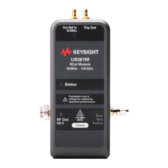
2.4 mm male (option MMM) or 2.4 mm female (option MMF) U9361G 10 MHz - 67 GHz 1.85 mm male (option MMM) or 1.85 mm female (option MMF) U9361M 10 MHz – 110 GHz 1.0 mm male (option MMM) U9361C/F/G/M RCal Receiver Calibrator Measurement Guide... -
Page 5: Rcal I/O
RCal be connected to the external 10 MHz Ref Out from the signal analyzer, or another reference that both RCal and the analyzer are locked to. The default setting of the RCal is Ref = External. U9361C/F/G/M RCal Receiver Calibrator Measurement Guide... -
Page 6: Rf Output
6 dB attenuator. Higher frequencies require smaller connector geometries, such as 1 mm. To avoid damaging these fragile connectors, please follow the recommendations in “Appendix: Connector Care” on page U9361C/F/G/M RCal Receiver Calibrator Measurement Guide... -
Page 7: Led Indicators On Rcal Module
Amber Blink = Temperature Unstable (during warm-up period) Red = USB Power Failure Red Blink = USB Power Failure Red Blink = External Ref unlocked Red Blink = Processor Error Blue Blink = Self Identification U9361C/F/G/M RCal Receiver Calibrator Measurement Guide... -
Page 8: Rcal Software - Configuration
(See “Available RCal Models and Options” on page This section provides an overview of how to perform the RCal configuration, calibration, and application. RCal calibrations are created and applied within the calibration configuration window. U9361C/F/G/M RCal Receiver Calibrator Measurement Guide... -
Page 9: Left-Panel Controls
RCal module with the signal analyzer for complex calibrations. Identify RCal Module: Identifies the active RCal module. If multiple RCal modules are connected to the signal analyzer, touching this key will cause LEDs on the active unit to flash. U9361C/F/G/M RCal Receiver Calibrator Measurement Guide... -
Page 10: Configuration Table Overview
1. Use Current Meas automatically populates the Cal Row using parameters from the current X-Series Signal Analyzer application. This feature is supported by the Signal Analyzer mode and many others, but it is not supported by every X-Series Signal Analyzer application. U9361C/F/G/M RCal Receiver Calibrator Measurement Guide... -
Page 11: Rcal Configuration Table - Parameters
Complex is only available if RCal Option only (no phase corrections). Use for swept CPX is installed. measurements. Complex: Select for correcting magnitude and phase. Use for correcting IF responses for IQ demodulation measurements. U9361C/F/G/M RCal Receiver Calibrator Measurement Guide... - Page 12 Swept is only used for Magnitude calibrations. Calibration is valid for the maximum Other paths for IQ demodulation include: bandwidth of the IF path. — 40 MHz — 160 MHz — 255 MHz — 520 MHz — 1 GHz U9361C/F/G/M RCal Receiver Calibrator Measurement Guide...
- Page 13 LO > RF or LO < RF). Alternate if using alternate-side mixing for digital demodulation to flip the side of image products, then you would want to calibrate the alternate mixing side. All does both. U9361C/F/G/M RCal Receiver Calibrator Measurement Guide...
- Page 14 False (default) allows instrument to interpolate and approximate when correction data is “close”; on page 18 for more details. reduces frequency of Apply errors. True requires strict match between correction data and instrument settings. U9361C/F/G/M RCal Receiver Calibrator Measurement Guide...
-
Page 15: Rcal Software - Calibration And Application
— The signal analyzer reads relevant factory calibration data from the RCal module to prepare for corrections. — The signal analyzer makes measurements and calculates the difference between expected and actual measurements. — The differences are stored as corrections to be applied to a later measurement. U9361C/F/G/M RCal Receiver Calibrator Measurement Guide... -
Page 16: Applying A Calibration
"RCal" in orange as shown below. The Apply indicator is dynamic; as you change analyzer settings, RCal will re-evaluate to check if any RCal corrections in the active correction pool are applicable. U9361C/F/G/M RCal Receiver Calibrator Measurement Guide... -
Page 17: Errors, Warnings, And Status
In most applications, the state parameters of a given measurement can be found and set via: — The “Meas Bar” summary (at top of screen) — The Meas Setup menu Best RCal Configuration Practices The following recommendations should be considered when creating RCal calibration states: U9361C/F/G/M RCal Receiver Calibrator Measurement Guide... -
Page 18: Multiple Sa Input Ports And Rcal Modules
This overlap may be over a portion of the spectrum trace. This usually is undesired, and should be avoided or fixed by: — Selecting Apply in a single row, or fewer rows, until the warning goes away, or configuring RCal to avoid overlap. U9361C/F/G/M RCal Receiver Calibrator Measurement Guide... -
Page 19: Key Steps For Every Rcal Calibration
2. Make sure that the Ext 10 MHz reference is connected and that the selected USB connection supplies ample current. 3. If source control is desired for the calibration, connect the necessary input and output triggers between the analyzer and source. U9361C/F/G/M RCal Receiver Calibrator Measurement Guide... -
Page 20: Demonstrations
— The Trig connections between the signal generator and signal analyzer are recommended for demos involving source control. The software trigger can also be used without a physical connection. — The USB-C connection is located above the Ext Ref In and Trig Out ports, as shown below. U9361C/F/G/M RCal Receiver Calibrator Measurement Guide... - Page 21 1. Connect your signal generator to the LAN or to the SA through GPIB. 2. Navigate to Meas Setup > Select Source. 3. Add the source address using GPIB or LAN, highlight it, then choose Select Highlighted Source to add the source. U9361C/F/G/M RCal Receiver Calibrator Measurement Guide...
-
Page 22: Demo #1 - Simple Magnitude Calibration
1. Connect the RF output of the signal generator to the RF input of the signal analyzer with the attenuator in between. On the Spectrum Analyzer: 2. Select Mode Preset to set the analyzer to a known state. U9361C/F/G/M RCal Receiver Calibrator Measurement Guide... - Page 23 Demonstrations 3. Select Freq and set the Start Freq to 3 GHz and Stop Freq to 4 GHz. 4. Select Sweep > Sweep Config and set the Points to 101. U9361C/F/G/M RCal Receiver Calibrator Measurement Guide...
- Page 24 7. Set RF Out > On. The RF output state is indicated by the LED next to the toggle button. On the signal analyzer: 1. Select Trace. In the Select Trace drop-down, select Trace 1. 2. Set Trace Type to Max Hold, and then in the View/Blank area, select Active. U9361C/F/G/M RCal Receiver Calibrator Measurement Guide...
- Page 25 The trace will begin to flatten as the maximum points are saved. 3. Once the trace has stabilized, save it for comparison by selecting View in the View/Blank area. 4. Disconnect the RF cable from the signal generator and connect it to the RCal module. U9361C/F/G/M RCal Receiver Calibrator Measurement Guide...
- Page 26 7. When calibration is complete, select Apply, then Close the window. 8. Disconnect the cable from the RCal RF Out port and connect it to the signal generator RF Out port. U9361C/F/G/M RCal Receiver Calibrator Measurement Guide...
- Page 27 10. Set Trace Type to Max Hold, and then in the View/Blank area, select View Active. The trace will begin to flatten as the maximum points are saved. Notice the improvement in the measurement. U9361C/F/G/M RCal Receiver Calibrator Measurement Guide...
-
Page 28: Demo #2 - Magnitude Cal With Source Control, Multiple States
On the Signal Analyzer: 1. Select Mode > Spectrum Analyzer > Mode Preset to set the signal analyzer to a known state. 2. Select FREQ > Start Freq > 24 GHz 3. Stop Freq > 25 GHz U9361C/F/G/M RCal Receiver Calibrator Measurement Guide... - Page 29 5. Select Meas Setup> Source> Source Mode> Tracking to set up the source control to sweep across the frequency range 6. Select RF Output > Off SW or External Trigger can be selected under the Source Setup table menu. U9361C/F/G/M RCal Receiver Calibrator Measurement Guide...
- Page 30 10.Once the trace has stabilized, save it for comparison by setting View > View. 11.Disable the RF output on the signal generator from Meas Setup > Source > RF Output > Off. 12.Disconnect the cable from the signal generator and connect it to the RCal module. U9361C/F/G/M RCal Receiver Calibrator Measurement Guide...
- Page 31 15. When the calibration is complete, select the Apply box. 16. Disconnect the cable from the RCal module and connect it to the RF output of the signal generator. 17. Select Source > RF Output > On to enable the signal generator output. U9361C/F/G/M RCal Receiver Calibrator Measurement Guide...
- Page 32 Set Trace Type > Max Hold and set View > Active Wait for the trace to stabilize, then select View > View to store the trace. μ 19.Change the W path to Bypass: Presel Bypass by selecting μW Path > Bypass U9361C/F/G/M RCal Receiver Calibrator Measurement Guide...
- Page 33 Select Row 1 > Duplicate Row > uW Path Ctrl > uW Presel Bypass 24. Clear the Calibrate check box on row 1 and select Calibrate on the new row. U9361C/F/G/M RCal Receiver Calibrator Measurement Guide...
- Page 34 Now the trace should be properly corrected and without errors. 27.View the new trace by adding a 3rd trace. Trace > Select Trace > Trace 3 Trace Type > Max Hold View > Active U9361C/F/G/M RCal Receiver Calibrator Measurement Guide...
- Page 35 Demonstrations Observe the differences between the uncorrected trace (Trace 1), the corrected trace (Trace 2), and the corrected trace with Preselector Bypass enabled (Trace 3). U9361C/F/G/M RCal Receiver Calibrator Measurement Guide...
-
Page 36: Demo #3 - Complex Cal: Improving Evm In A 128 Qam Signal
3. Configure the signal generator using the following settings: FREQ > 5GHz AMPTD > -10dBm Mode > Arb Custom Modulation > Single Carrier Setup > Modulation Type > Select > QAM > 128 QAM U9361C/F/G/M RCal Receiver Calibrator Measurement Guide... - Page 37 Ctr (Center Frequency) > 5GHz Format > 128-QAM Sym Rate > 10MHz Info BW > 20MHz You should now see the constellation, signal, and metrics. 6. On the signal generator, enable trace averaging to smooth the signal. U9361C/F/G/M RCal Receiver Calibrator Measurement Guide...
- Page 38 8. Disconnect the cable from the signal generator and connect it to the RCal module. 9. Navigate to the RCal Calibration Configuration window. Input/Output > Calibration > Configuration The Calibration Configuration table should be unpopulated. U9361C/F/G/M RCal Receiver Calibrator Measurement Guide...
- Page 39 Elec Atten: Bypass IF Gain: Auto IF Path: 25 MHz Preamp: Off Coupling: AC Phase Noise Opt: Best Wide Offset uW Path Ctrl: uW Presel Bypass 11.Run the calibration after selecting the calibrate check box. U9361C/F/G/M RCal Receiver Calibrator Measurement Guide...
- Page 40 The EVM should now be improved, as shown in the comparison below. 14.Change the RF path to use the Yig Tuned Filter (Standard Path). µW Path > Standard µ This will generate a warning, since the current corrections only apply to the W Bypass Path. U9361C/F/G/M RCal Receiver Calibrator Measurement Guide...
- Page 41 17.Navigate to the RCal Calibration Configuration window. Input Output > Calibration > Configuration 18.Duplicate the existing state and change the new state’s RF path. Select Row 1> Duplicate Row> µW Path Ctrl > Standard U9361C/F/G/M RCal Receiver Calibrator Measurement Guide...
- Page 42 RF output on the signal generator. RF Output > On The EVM is now reduced to 0.12% with the Standard path. By leaving both paths applied, the instrument will automatically select the proper calibration state. U9361C/F/G/M RCal Receiver Calibrator Measurement Guide...
-
Page 43: Demo #4 - Using Rcal With The 89600 Vsa Software
1. Start the VSA application. Mode/Measure > Launch VSA 2. Configure the Trace Layout to be a 2x2 grid. Window > Trace Layout > Grid 2x2 3. Set the Measurement Type to Digital Demod. U9361C/F/G/M RCal Receiver Calibrator Measurement Guide... - Page 44 4. Open the Digital Demod Properties tab. Meas Setup > Digital Demod Properties 5. Configure the following measurement parameters under the Format tab. Format: 128-QAM Symbol Rate: 10 MHz Points/Symbol: 10 Result Length: 501 Symbols U9361C/F/G/M RCal Receiver Calibrator Measurement Guide...
- Page 45 6. Under the Filter tab, set the following matched filter parameters. Measurement Filter > Root Raised Cosine Reference Filter > Raised Cosine Alpha/BT: (rolloff) > 0.5 7. Set the IF Path to 25 MHz. Input > Extensions > IF Path> 25 MHz U9361C/F/G/M RCal Receiver Calibrator Measurement Guide...
- Page 46 8. Under the same Extensions window, scroll down and enable RCal Corrections. RCal Correction > Correction 9. Perform an Auto-range by selecting the button shown below. 10.Exit the input window. EVM should now be improved. For this example, EVM went from 1.02% to 0.188%. U9361C/F/G/M RCal Receiver Calibrator Measurement Guide...
-
Page 47: Demo #5 - Rcal Vs. Power Sensor Accuracy
2. Connect the signal analyzer to the signal generator. 3. Set start frequency to 1 GHz and stop frequency to 20 GHz. FREQ > Start Freq > 1 GHz Stop Freq > 20 GHz U9361C/F/G/M RCal Receiver Calibrator Measurement Guide... - Page 48 4. Set the number of sweep points to 101. Sweep > Sweep Config > Points > 101 5. Set up source control to automatically sweep across the frequency range. Meas Setup > Source Source Mode > Tracking RF Output > On U9361C/F/G/M RCal Receiver Calibrator Measurement Guide...
- Page 49 7. Prepare to store the uncorrected trace. Trace > Select Trace > Trace 1 Trace Type > Max Hold View > Active 8. Once the trace has stabilized, save it for comparison. View > View U9361C/F/G/M RCal Receiver Calibrator Measurement Guide...
- Page 50 10.Disconnect the cable from the signal generator and connect it to the RCal module. 11.Navigate to the RCal Calibration Configuration Window. Input Output > Calibration > Configuration The Calibration Configuration Table should be unpopulated. U9361C/F/G/M RCal Receiver Calibrator Measurement Guide...
- Page 51 Calibrate > Calibrate > Checked Rows 14.When calibration is complete, select Apply. 15.Disconnect the cable from the RCal module and connect it to the signal generator. Enable the RF output on the signal generator. RF Output > On U9361C/F/G/M RCal Receiver Calibrator Measurement Guide...
- Page 52 The results have been tabulated below. TX power is -10 dBm. Frequency (GHz) Power Sensor (dBm) RCal Corrected Difference (Abs) -10.07 -10.01 0.06 -10.06 -9.996 0.064 -10.35 -9.881 0.469 -9.97 -10.08 0.11 -9.91 -10.16 0.25 U9361C/F/G/M RCal Receiver Calibrator Measurement Guide...
- Page 53 -10.12 -10.08 0.04 -10.36 -10.01 0.35 The average difference in results between the Power Sensor and the measurement using an RCal calibration for this test case was 0.192 dBm across the selected measurement span. U9361C/F/G/M RCal Receiver Calibrator Measurement Guide...
-
Page 54: Demo #6 - Using Rcal As A Cw Source And Comb Generator
— Comb Spacing: Select the spacing of the frequency comb when using a comb signal The table below gives minimum and maximum frequency and comb spacing options when using Calibrator Control: Minimum Maximum Frequency 10 MHz 110 GHz Comb Spacing 100 kHz 1.344 GHz U9361C/F/G/M RCal Receiver Calibrator Measurement Guide... - Page 55 Demonstrations Example Calibrator Control Outputs: CW signal at 10 GHz. The amplitude of the signal can be adjusted using external attenuation. Comb signal centered at 10 GHz with 100 kHz spacing. U9361C/F/G/M RCal Receiver Calibrator Measurement Guide...
- Page 56 Demonstrations Comb signal centered at 10 GHz with 100 MHz spacing. U9361C/F/G/M RCal Receiver Calibrator Measurement Guide...
-
Page 57: Programming With Matlab
':FREQ:SPAN %dGHz', freq_span); fprintf(my_SG, ':POW %ddBm', amp); % Set X-Series Signal Analyzer to basic mode, set trace to <> hold order to see avg. power % level before calibration fprintf(my_SA, ':INST:SEL SA'); fprintf(my_SA, ':SYST:PRES:TYPE MODE'); U9361C/F/G/M RCal Receiver Calibrator Measurement Guide... -
Page 58: Calibration Table Setup For Vma
= 6; % Input ID (VISA, IP, etc.) SA_address = 'USB0::0x2A8D::0x0D0B::MY49431812::0::INSTR' SG_address = 'USB0::0x0957::0x1F01::MY53050777::0::INSTR' % Create VISA objects for your X-Series Signal Analyzer and Power Source my_SA = visa('keysight', SA_address); my_SG = visa('keysight', SG_address); U9361C/F/G/M RCal Receiver Calibrator Measurement Guide... - Page 59 IF_path = 'B100M' % Assume Single-Carrier (Add additional frequency range for OFDM) center_frequency_num = str2num(center_frequency) freq_start = num2str(center_frequency_num) freq_stop = num2str(center_frequency_num) % Now populate an RCal State with the instrument parameters fprintf(my_SA, ':SYST:CAL:CGR %d', cal_group) U9361C/F/G/M RCal Receiver Calibrator Measurement Guide...
- Page 60 % Mixing Mode and Match State are default on new row addition % Uncomment below to automatically calibrate for single added row % input('Switch cable from SG to RCal Unit, then press ''enter''...', 's'); % fprintf(my_SA, ':SYST:CAL:INIT:SEL') U9361C/F/G/M RCal Receiver Calibrator Measurement Guide...
-
Page 61: Appendix: Connector Care
1. Inspect the connectors for dust, dirt, metal fragment, oils or film, and debris. 2. Blow off any dust with a filtered, clean supply of compressed air. 3. Add a few drops of high-purity isopropyl alcohol to a small cleaning swab (do not apply U9361C/F/G/M RCal Receiver Calibrator Measurement Guide... - Page 62 2. Burrs or blisters 3. Deformed threads 4. Center conductors — Bent — Broken — Misaligned — Concentricity 5. Connector nuts should move smoothly and be free of: — Burrs — Loose metal particles U9361C/F/G/M RCal Receiver Calibrator Measurement Guide...
-
Page 63: Resources
Resources Resources U9361x Product Pages: U9361C RCal Receiver Calibrator, 10 MHz to 26.5 GHz U9361F RCal Receiver Calibrator, 10 MHz to 50 GHz U9361G RCal Receiver Calibrator, 10 MHz to 67 GHz U9361M RCal Receiver Calibrator, 10 MHz to 110 GHz... - Page 64 This information is subject to change without notice. © Keysight Technologies 2021-2022 Edition 1, October 2022 U9361-90003 www.keysight.com...
Need help?
Do you have a question about the U9361C and is the answer not in the manual?
Questions and answers