Table of Contents
Advertisement
Quick Links
Keysight Technologies
U3045AM04
Multiport Test Set Extension
NOTICE: This document contains references to
Agilent Technologies. Agilent's former Test and
Measurement business has become Keysight
Technologies. For more information, go to
www.keysight.com.
Use this manual with the following documents:
PNA or PNA-X Network Analyzer On-line Help
System
User's and
Service Guide
Advertisement
Table of Contents
Troubleshooting

Related Manuals for Keysight Technologies U3045AM04


Summary of Contents for Keysight Technologies U3045AM04
- Page 1 Keysight Technologies U3045AM04 Multiport Test Set Extension NOTICE: This document contains references to Agilent Technologies. Agilent’s former Test and Measurement business has become Keysight Technologies. For more information, go to www.keysight.com. Use this manual with the following documents: PNA or PNA-X Network Analyzer On-line Help System User’s and...
- Page 2 COVERING THE MATERIAL IN THIS DOCUMENT THAT CONFLICT WITH government requirements THESE TERMS, THE WARRANTY beyond those set forth in the © Keysight Technologies, Inc. 2012, TERMS IN THE SEPARATE EULA shall apply, except to the 2014, 2017 AGREEMENT WILL CONTROL.
-
Page 3: Table Of Contents
N5244A or N5245A RF Interface Cable Connections (U3021-60089) Test Set I/O Cable Installation Interconnect Cable Verification System Operational Check Equipment Setup Check Results Controlling the U3045AM04 Typeface Key Conventions Sweep Setup for Multiport and Standalone Modes Multiport Mode Keysight U3045AM04 User’s and Service Guide... - Page 4 Setting the Analyzer to Standalone Mode Operational Check with Cal Kit Verification Limits Equipment Required Operational Check Procedure Preparing the Analyzer 1-Port Calibration and Verification Procedure Verifying a Cal Kit Operational Check Failure ECal Confidence Check Service Information Keysight U3045AM04 User’s and Service Guide...
- Page 5 Troubleshooting Diagrams and Tables Safety and Regulatory Information Introduction Safety Earth Ground Declaration of Conformity Statement of Compliance Before Applying Power Servicing Connector Care and Cleaning Precautions Electrostatic Discharge Protection Regulatory Information Instrument Markings Battery Keysight U3045AM04 User’s and Service Guide...
-
Page 6: Keysight U3045Am04 User's And Service Guide
EMC Compliance South Korea Class A EMC Declaration Safety Acoustic Statement Keysight Support, Services, and Assistance Service and Support Options Contacting Keysight Shipping Your Product to Keysight for Service or Repair Keysight U3045AM04 User’s and Service Guide... - Page 7 U3045AM04 Keysight U3045AM04 User’s and Service Guide...
-
Page 8: Introduction
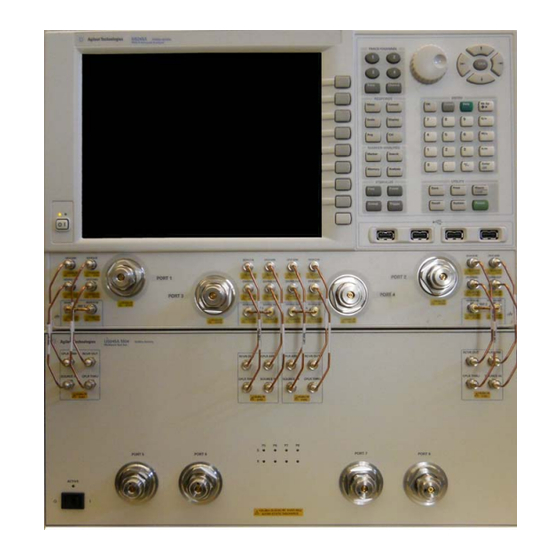
U3045AM04 Introduction Introduction This document describes how to use and service the U3045AM04 Multiport Extension Test Set. Figure 1 Front Panel N5245A with U3045AM04 Keysight U3045AM04 User’s and Service Guide... -
Page 9: Description
U3045AM04 Description Description The Keysight U3045AM04 is a Multiport Test Set that adds 4 ports to extend the 4-Port network analyzer to 8 full crossbar test ports with N-Port calibration capability. The Keysight U3045AM04 has the following key features: — 4 test ports (2.4 mm male connectors) —... -
Page 10: Network Analyzer Requirements
Ensure that the network analyzer has the latest version of firmware installed. The following web site links provide the necessary information needed: — Documentation - http://www.keysight.com/find/pna — Network Analyzer Firmware - http://na.support.keysight.com/pna/firmware/firmware.html — U3045AM04 Test Set Files - http://na.support.keysight.com/multiport/testsets/testset_files.html Keysight U3045AM04 User’s and Service Guide... -
Page 11: Available Options
— U3045AM04-1CN Front Handle Kit (5063-9228) Network Analyzer Interface Kit Options The U3045AM04 requires one of the following kits to interface the test set with your network analyzer. The interface kit model option includes the hardware lock-link and cable kit listed in... -
Page 12: General Specifications
— N5244A and N5245A maximum power is 450 W. — U3045AM04 maximum power is 350 W. This is a Safety Class I Product (provided with a protective earthing ground incorporated in the power cord). The mains plug shall be only be inserted in a socket outlet provided with a protective earth contact. -
Page 13: Environmental Requirements
For weight, dimensions and space requirements, refer to the network analyzer documentation that is used to configure the test set. Keysight U3045AM04 User’s and Service Guide... -
Page 14: Maximum Power Levels
It is recommended that you do not operate components near damage levels (+28 dBm). The power levels must be 3 dB below maximum level to ensure no damage. Table 4 Maximum Power Levels U3045AM04 Test Port RF Power Levels: PORT 5-8 +25 dBm U3045AM04 Access Ports: SOURCE OUT... -
Page 15: Typical Reflection Tracking
25 GHz to 30 GHz –6.0 –4.0 30 GHz to 35 GHz –6.5 –4.5 35 GHz to 40 GHz –7.0 –5.0 40 GHz to 45 GHz –7.5 –5.5 45 GHz to 50 GHz –8.5 –6.0 Keysight U3045AM04 User’s and Service Guide... -
Page 16: Front And Rear Panel Features
Standby Switch Note that this switch is Standby only, not a line switch. The main power cord can be used as the system disconnecting device. It disconnects the mains circuits from the mains supply. Keysight U3045AM04 User’s and Service Guide... - Page 17 The detachable power cord is the instrument disconnecting device. It disconnects the mains circuits from the mains supply before other parts of the instrument. The front panel switch is Keysight U3045AM04 User’s and Service Guide...
- Page 18 For continued protection against fire hazard, replace fuses, only with same type and ratings. The use of other fuses, circuit breakers or materials is prohibited. Line Fuse Figure 4 Verify that the premise electrical voltage supply is within the range specified on the instrument. Keysight U3045AM04 User’s and Service Guide...
-
Page 19: Hardware Lock-Link Installation (U3021-60002)
2. Remove the feet from the bottom of the analyzer. 3. Remove the 2 lower standoffs from the rear panel on the analyzer using a T20 Torx driver. Figure 5 Rear and Bottom Feet Standoffs (x2) Feet (x4) Keysight U3045AM04 User’s and Service Guide... - Page 20 6. Install the left and right lock-links onto the test set, as shown in Figure Figure 7 Install Lock-links to the Test Set Right lock-link Left Lock-link N5242-20138 N5242-20139 Screw 0515-2317 (x2) T15 M3.5X0.6 12 mm Keysight U3045AM04 User’s and Service Guide...
- Page 21 8. Secure the analyzer’s lower lock-links to the test set’s upper lock-link using the spring–loaded screws. If the analyzer's lock-links are not aligned with the screw holes, loosen the screws securing the feet to the instrument to align and tighten. Figure 9 Locked Keysight U3045AM04 User’s and Service Guide...
-
Page 22: N5244A Or N5245A Rf Interface Cable Connections (U3021-60089)
Figure 10 illustrates the final two digits of the part number for each cable. The cables must be connected in the numeric order listed in Table Figure 10 RF Interface Connections 16 (x8) 17 (x8) Keysight U3045AM04 User’s and Service Guide... -
Page 23: Test Set I/O Cable Installation
“System Operational Check” on page 2. If the problem still exists, perform the “RF Switching Failures” on page 3. If a power hole or other failure still exists, refer to “Contacting Keysight” on page Keysight U3045AM04 User’s and Service Guide... -
Page 24: System Operational Check
Reflection Response Results Reflection Port Response Trace Cable Path Diagram Ports 1-4 Figure 12 on page 19 Figure 13 on page 19 Ports 5-8 Figure 14 on page 20 Figure 15 on page 20 Keysight U3045AM04 User’s and Service Guide... - Page 25 S201 S300 S301 S400 S401 <= Src Rec => <= Src Rec => <= Src Rec => <= Src Rec => Agilent U3042A-E04 Solid State Switches Port 5 Port 6 Port 7 Port 8 Keysight U3045AM04 User’s and Service Guide...
- Page 26 S201 S300 S301 S400 S401 <= Src Rec => <= Src Rec => <= Src Rec => <= Src Rec => Agilent U3042A-E04 Solid State Switches Port 5 Port 6 Port 7 Port 8 Keysight U3045AM04 User’s and Service Guide...
-
Page 27: Controlling The U3045Am04
Stepped Sweep is available on all models. 1. On the analyzer select STIMULUS > Sweep > Sweep Setup. 2. Select Stepped Sweep. 3. Set the Dwell Time to 5 μs > OK. Figure 16 Sweep Setup Keysight U3045AM04 User’s and Service Guide... -
Page 28: Multiport Mode
The current version of the test set files are available on the web at http://na.support.keysight.com/multiport/testsets/testset_files.html. Copy the appropriate file to c:\program files\Keysight\Network Analyzer\testsets directory. Selecting Multiport Mode Figure 17 Keysight U3045AM04 User’s and Service Guide... -
Page 29: External Test Set Control Operation
This menu will allow the physical Ports 1 thru 8 to be identified as any port for your convenience. For example, Port 5 can be re-named Port 2. The External Test Set Control-U3045AM04 also allows control of the DUT control lines, refer to “Control Lines”... -
Page 30: Selecting S-Parameter Measurement
Figure 19 S-Parameter Measurement Selecting New S-Parameter Measurement S-Parameter Tab: Multiple S-Parameters can be made by selecting Trace/Chan > Trace > New Trace. Use the drop-down menu and select of any of the 64 S-Parameter's. Keysight U3045AM04 User’s and Service Guide... -
Page 31: Balanced Tab
For more information on balanced (differential) component measurement, refer to the Application Note 1373-1 and 1373-2 (5988-5634EN and 5988-5635EN) at http://www.keysight.com. In the search menu type “Multiport and Balanced.” Selecting Balanced Measurements Figure 21 Keysight U3045AM04 User’s and Service Guide... -
Page 32: Receivers Tab
U3045AM04 Controlling the U3045AM04 Receivers Tab The S-Parameter measurements can be ratioed with selectable Denominators for each port and receiver. Refer to the standard documentation for more information. Figure 22 Receiver Measurements Keysight U3045AM04 User’s and Service Guide... -
Page 33: N-Port Calibration With The Analyzer
Measurement errors can be a result of firmware algorithms. Consult with Keysight Service or firmware web page for the latest analyzer Option 551 firmware revisions and history. http://na.support.keysight.com/pna/firmware/firmware.html Figure 23 ECal Characterization Keysight U3045AM04 User’s and Service Guide... - Page 34 If using a mechanical cal kit, select SmartCal (Guided Calibration) > Next. b. If using an ECal module, connect the ECal to an available USB port on the analyzer and select Use Electronic Calibration (ECal) > Next. Keysight U3045AM04 User’s and Service Guide...
- Page 35 See “On the analyzer select Response > Cal Wizard.” on page 28. Refer to the analyzer’s Help system for calibration information using an ECal module. Figure 26 Select Calibration Ports Figure 27 Factory Calibration Keysight U3045AM04 User’s and Service Guide...
- Page 36 If measurement errors occur, ensure the newest version of firmware is installed on the analyzer. Measurement errors can be a result of firmware algorithms. Consult with Keysight Service or firmware web page for the latest Option 551 firmware revisions and history. http://na.support.keysight.com/pna/firmware/firmware.html. Keysight U3045AM04 User’s and Service Guide...
-
Page 37: Interface Control Mode
— Control data is sent in the following order and this order cannot be changed: Refer to the analyzer’s Help menu. 1. GPIB Interface 2. Material Handler Interface 3. Test Set Interface 4. Dwell Time Keysight U3045AM04 User’s and Service Guide... -
Page 38: How To Access Interface Control Mode
Please review this application before connecting the test set to the analyzer. Information regarding this application can be found in the analyzer Help menu, Interface Control. The application is shown Figure 28 below. Figure 28 Interface Control Keysight U3045AM04 User’s and Service Guide... -
Page 39: Using Interface Control Mode
The quantity of Test Set I/O entries that can be entered is limited by the available memory of the analyzer. Address and Data example: addr.data (3) 16.1 32.2 Keysight U3045AM04 User’s and Service Guide... - Page 40 Word Pad. Applies the settings and closes the dialog box. Cancel: Does not apply changes that were made and closes the dialog box. Help: Provides additional information for using the interface control application. Keysight U3045AM04 User’s and Service Guide...
-
Page 41: Gpib Control Mode
GPIB Command Processor Console in the analyzer’s Help menu. — GPIB Command Processor settings can not be saved or recalled. — Address and data can be written from the GPIB Command Processor. Keysight U3045AM04 User’s and Service Guide... -
Page 42: How To Access Gpib Command Processor
Figure 17 on page 3. To access the GPIB Command Processor select Utility > System > Configure > SICL/GPIB/SCPI. Figure 30 Utility Configure 4. Select GPIB Command Processor Console > OK. Figure 31 GPIB Command Processor Keysight U3045AM04 User’s and Service Guide... -
Page 43: Gpib Command Processor Console
Address and data are separated by a comma. Commands are executed by a carriage return or the Enter key. For example: CONT:EXT:TEST:DATA <address>,<data> CONT:EXT:TEST:DATA 0,0 Example: CONT:EXT:TEST:DATA 0,0 Refer to “Address and Data Values” on page Keysight U3045AM04 User’s and Service Guide... -
Page 44: Address And Data Values
Source Port 1 = address 0, data 0 and Receiver Port 5 = address 0, data 16. The data values are added together, the entry will be 0.16. Table 8 Test Port Address and Data Values Address Source Path Receiver Path Data Ports Ports Ports Ports Keysight U3045AM04 User’s and Service Guide... - Page 45 Address and Data Values Figure 32 Address and Data Example 1 (Port 5 and 6) PNA-X Address 16 Address 0 Port 1 Port 3 TEST SET Port 5 Port 6 Source Port Receiver Port Keysight U3045AM04 User’s and Service Guide...
-
Page 46: Control Lines
100 mA (each line) Control Line DC resistance < 10 Ω (each line) Voltage Range: Positive Input 0 to +5 V Negative Input –5 to 0 V Internal Variable Voltage +2 to +5 V Keysight U3045AM04 User’s and Service Guide... - Page 47 Internal voltage output, adjusted with the trimmer on the rear panel. Positive Input Connection for internal (pin 12) or external positive voltage supply. Negative Input Connection for ground (pin 15) or external negative voltage supply. Ground terminal. Keysight U3045AM04 User’s and Service Guide...
-
Page 48: Internal Voltage Supply Configuration
You may only connect pin 12–13, and pin 14–15, damage may result if any other paths are short-circuited. Figure 34 Internal DC Power Configuration (rear panel view) Line 1 Line 2 (Rear Panel View) TO DUT (Only required Lines) Line 8 2 to 5 Vdc TEST SET Keysight U3045AM04 User’s and Service Guide... -
Page 49: External Voltage Supply Configuration
Test Set to the DUT and External DC Power Supply Line 1 Line 2 (Rear Panel View) TO DUT (Only required Lines) DC Power Supply Line 8 2 to 5 Vdc Positive: 0 to 5 Vdc Negative: 5 to 0 Vdc TEST SET Keysight U3045AM04 User’s and Service Guide... -
Page 50: Setting The Control Lines With Address And Data Values
DUT Control Line 6 set to logic low or connected to Pin 14 DUT Control Line 7 set to logic low or connected to Pin 14 DUT Control Line 8 set to logic low or connected to Pin 14 Keysight U3045AM04 User’s and Service Guide... - Page 51 3. The SUM of the <data> values = 6 4. Front panel analyzer Interface Control Mode line entry = 112.6 > OK. Since all control lines have the same <address>, only one "<address>.<data>" command line is needed to control all 8 lines. Keysight U3045AM04 User’s and Service Guide...
-
Page 52: Operational Check With Cal Kit
The following procedure can be used to confirm 1-Port Cal performance of an ECal Module or Mechanical Cal Kit. The operation verification limits provided ensure that your U3045AM04 and analyzer are operating properly. Refer to “Verifying a Cal Kit Operational Check Failure” on page 52... -
Page 53: Equipment Required
U3045AM04 Operational Check with Cal Kit Equipment Required The Keysight U3045AM04 requires that the user be familiar with the equipment listed. Table 13 Equipment List Description N4693A 2.4 mm ECal Module 10 MHz to 50 GHz (Option 00F or M0F) or Mechanical cal kit... - Page 54 1-Port Calibration on Port 1. On the analyzer, select Response > Cal > Start Cal > Calibration Wizard” as shown on page 49. 12.Allow the ECal module, test set and analyzer to warm up for a minimum of 30 minutes. Keysight U3045AM04 User’s and Service Guide...
-
Page 55: 1-Port Calibration And Verification Procedure
If you do not have a key board, select Save As User Calset > Edit Name and save as 999.x. X is the port number you are calibrating. Use the numeric keypad on the analyzer's front panel to enter “999.1.” Keysight U3045AM04 User’s and Service Guide... - Page 56 Calibration, Cal Set Viewer 10.From the Cal Sets drop-down menu, select 999.1 and select Enable. Select the Reflection Tracking(x,x), where x,x is the port being tested. Ensure that the Enable and Error Terms check boxes are selected. Keysight U3045AM04 User’s and Service Guide...
- Page 57 (1,1) trace to the appropriate limits in Table 4 on page 8. The trace should be above the limit.” on page 51 for Cal Sets “999.1” thru “999.8” (8-Port). Figure 39 Reflection Tracking Trace (Port 1-4) Keysight U3045AM04 User’s and Service Guide...
-
Page 58: Verifying A Cal Kit Operational Check Failure
The following procedure is a method to verify the accuracy of a 1-Port calibration performed with mechanical standards or an ECal module. To perform this check, the test port of the ECal module must connect directly to the Test Port being verified (without adapters). Keysight U3045AM04 User’s and Service Guide... - Page 59 S-parameter Apply > OK > Read Module Data. 6. When the "Select ECal Module" prompt appears, select the ECal module you are using and the ECal Module Memory and Factor ID > OK. Figure 41 ECal Confidence Check Keysight U3045AM04 User’s and Service Guide...
-
Page 60: Service Information
U3045AM04 Service Information Service Information This section provides information to troubleshoot and repair the U3045AM04 test set. Refer to “Keysight Support, Services, and Assistance” on page 82 information on returning your test set to Keysight Technologies. No operator serviceable parts inside. Refer servicing to qualified personnel. - Page 61 Screw-Pan Head Machine with thread patch, 0515-2317 Torx-T15 M3.5 with 0.6 thread, 12 mm-LG Lock-link Kit (N5242 PNA-X to a 421.6 mm or a U3021-60002 N5245 PNA-X to a 497.8 mm instrument) Cable Kit, Interface U3021-60089 Keysight U3045AM04 User’s and Service Guide...
-
Page 62: System Block Diagram
RCVR A IN SOURCE OUT CPLR THRU CPLR ARM RCVR C IN SOURCE OUT CPLR THRU CPLR ARM RCVR D IN SOURCE OUT CPLR THRU CPLR ARM RCVR B IN SOURCE OUT CPLR THRU Keysight U3045AM04 User’s and Service Guide... - Page 63 U3045AM04 Service Information Figure 43 U3045AM04 Electrical Diagram AC IN Test Set Interface Pass Thru Interface Ext. DUT Control Keysight U3045AM04 User’s and Service Guide...
-
Page 64: Theory Of Operation
Source Output path to Analyzer Port 4 and Test Set Port 7. In the state shown in the block diagram, switch 30 routes the RF Source back to the Analyzer Port 4, and Test Set Source path to Port 7 is terminated. Keysight U3045AM04 User’s and Service Guide... - Page 65 Receiver Input path to Analyzer Port 2 and Test Set Port 8. In the state shown in the block diagram, switch 43 routes Port 2 Coupler Arm to the Receiver, and Test Set Port 8 Coupler Arm path is terminated. Keysight U3045AM04 User’s and Service Guide...
-
Page 66: Troubleshooting The Test Set
U3045AM04 Service Information Troubleshooting the Test Set If the U3045AM04 is not operating properly, use the following procedures to isolate and repair the type of failure encountered. It is recommended that a qualified service technician perform the following procedures. Refer to the Keysight PNA Series: Service & Support Home Page at: http://na.support.keysight.com/pna... - Page 67 "Step 2. “Using Multiport Mode (Option 551), verify that the analyzer’s firmware is correct, and that the test set file is loaded into the analyzer. Refer to 'Network Analyzer Requirements' on page 4." on page 63. Keysight U3045AM04 User’s and Service Guide...
- Page 68 Verify that the control voltage pin connections to the DUT control lines are connected properly. Refer to “Control Lines” on page b. Verify that the rear panel DC voltage control adjustment can be set to 5 Vdc. Refer to Figure 3 on page Keysight U3045AM04 User’s and Service Guide...
-
Page 69: Rf Switching Failures
Driver board, if the LEDs remain Off replace the Controller board. b. If the Status LEDs are On and the front panel Active LED is On, suspect the front panel LED board or the ribbon cable (replace as needed). Keysight U3045AM04 User’s and Service Guide... -
Page 70: Test Set Rf Switching Path
The <addrs>.<data> entries noted in the following Test Instructions table will be used to configure the RF switches for this testing. After making your entry select <OK> to execute the command, to return back for further entries, select Interface Control on the analyzer’s display. Keysight U3045AM04 User's and Service Guide... -
Page 71: Cable Connections
Source IN to Port 7 32.1 P7 CPLR, S30 Source IN to Port 8 64.1 P8 CPLR, S40 Figure 47 on page 66 1. Use the Source IN port associated with this group of test ports. Keysight U3045AM04 User's and Service Guide... - Page 72 U3045AM04 Service Information Figure 47 Source IN to Ports 5 to 8 Path Response Keysight U3045AM04 User's and Service Guide...
-
Page 73: Receiver Signal Path Insertion Loss Test
RCVR OUT to Ports 8 64.16 P8 CPLR, S43 page 67 1. Use the RCVR OUT port associated with this group of test ports. Figure 48 RCVR OUT to Ports 5 to 8 Path Response Keysight U3045AM04 User's and Service Guide... -
Page 74: Source In To Cplr Thru & Rcvr Out To Cplr Arm Path Test
Group <Address>.<Data> Components Port 5 RCVR OUT to CPLR ARM Port 6 RCVR OUT to CPLR ARM 16.0 Port 7 RCVR OUT to CPLR ARM 32.0 Port 8 RCVR OUT to CPLR ARM 64.0 Keysight U3045AM04 User's and Service Guide... - Page 75 U3045AM04 Service Information Figure 49 Source IN to CPLR THRU & RCVR OUT to CPLR ARM Path Response Keysight U3045AM04 User's and Service Guide...
-
Page 76: Rf Performance Failures
The following procedures can be used to isolate the failed component. Suspect the coax switches (N1811-60023), RF cables, or coupler (5087-7793). The RF performance of the U3045AM04 depends on the performance of the network analyzer. Ensure the network analyzer is meeting specification before continuing. -
Page 77: Troubleshooting Diagrams And Tables
Path Connection 1 and 5 Source 1 and 5 Receiver 3 and 6 Source 3 and 6 Receiver 4 and 7 Source 4 and 7 Receiver 2 and 8 Source 2 and 8 Receiver Keysight U3045AM04 User's and Service Guide... - Page 78 Test Set Top View DUT Control Bd Test Set Switch Interface Control Bd (top Bd) (bottom Bd) Switches (x4) SW13 SW23 SW33 SW43 (Receiver Paths Switches (x4) (Source Paths) SW10 SW20 SW30 SW40 Coupler/Test Ports (x4) Keysight U3045AM04 User's and Service Guide...
- Page 79 U3045AM04 Service Information Figure 51 Test Set Bottom View Line Module Power Supply 5 A/250 V Fuse Fuse (x2) Keysight U3045AM04 User's and Service Guide...
-
Page 80: Safety And Regulatory Information
Declaration of Conformity A copy of the Declaration of Conformity is available upon request, or a copy is available on the Keysight Technologies web site at http://regulations.about.keysight.com/DoC/ Statement of Compliance This instrument has been designed and tested in accordance with CAN/CSA 22.2 No. -
Page 81: Before Applying Power
4 °C for every 100 watts dissipated in the cabinet. If the total power dissipated in the cabinet is greater than 800 watts, then forced convection must be used. This instrument has auto-ranging line voltage input, be sure the supply voltage is within the specified range. Keysight U3045AM04 User's and Service Guide... -
Page 82: Servicing
To prevent electrical shock, disconnect the Keysight Technologies U3045AM04 from mains electrical supply before cleaning. Use a dry cloth or one slightly dampened with water to clean the external case parts. Do not attempt to clean internally. -
Page 83: Electrostatic Discharge Protection
2. While wearing a grounded wrist strap, grasp the outer shell of the cable connector. 3. Connect the other end of the cable to the test port and remove the short from the cable. Keysight U3045AM04 User's and Service Guide... - Page 84 U3045AM04 Electrostatic Discharge Protection Figure 54 ESD Protection Setup Keysight U3045AM04 User's and Service Guide...
-
Page 85: Regulatory Information
Forty years is the expected useful life of the product. This symbol on all primary and secondary packaging indicates compliance to China standard GB 18455-2001. South Korean Certification (KC) mark; includes the marking's identifier code which follows the format: MSIP-REM-YYY-ZZZZZZZZZZZZZZ. Keysight U3045AM04 User's and Service Guide... -
Page 86: Battery
• IEC/EN 61010-1 • Canada: CSA C22.2 No. 61010-1 • USA: UL std no. 61010-1 Acoustic Statement (European Machinery Directive): • Acoustic noise emission LpA<70 dB Operator position Normal operation mode Per ISO 7779 Keysight U3045AM04 User's and Service Guide... -
Page 87: Keysight Support, Services, And Assistance Service And Support Options
Keysight for repair. If you wish to send your instrument to Keysight Technologies for service or repair: — To improve turn-around time, return your test set along with your analyzer and cables to Keysight so that we may verify the operation of the complete system. - Page 88 Keysight U3045AM04 User's and Service Guide...
- Page 89 This information is subject to change without notice. © Keysight Technologies 2012, 2014, 2017 Edition 1 February 2017 Supersedes: April 2014 www.keysight.com...
Need help?
Do you have a question about the U3045AM04 and is the answer not in the manual?
Questions and answers