Table of Contents
Advertisement
Quick Links
Advertisement
Table of Contents
Troubleshooting

Subscribe to Our Youtube Channel
Related Manuals for Juniper ACX7100-32C


Summary of Contents for Juniper ACX7100-32C
- Page 1 ACX7100-32C Cloud Metro Router Hardware Guide Published 2022-11-02...
- Page 2 The Juniper Networks product that is the subject of this technical documentation consists of (or is intended for use with) Juniper Networks software. Use of such software is subject to the terms and conditions of the End User License Agreement ("EULA") posted at https:/ /support.juniper.net/support/eula/.
-
Page 3: Table Of Contents
ACX7100-32C Router Description | 2 ACX7100-32C Router Models | 5 Field-Replaceable Units in ACX7100-32C Routers | 5 Hardware Redundancy of ACX7100-32C Router Components and Functionality | 6 ACX7100-32C Routers Hardware and CLI Terminology Mapping | 7 ACX7100-32C System Software Overview | 8... - Page 4 Environmental Requirements and Specifications for ACX7100-32C Routers | 35 Grounding Cable and Lug Specifications for ACX7100-32C | 36 Clearance Requirements for Hardware Maintenance of ACX7100-32C Routers | 38 Rack Requirements for ACX7100-32C Routers | 39 Cabinet Requirements for ACX7100-32C Routers | 40...
- Page 5 Connect ACX7100-32C to External Devices | 75 Connect an ACX7100-32C Router to a Management Console | 75 Connect an ACX7100-32C Router to a Network for Out-of-Band Management | 76 Connect an ACX7100-32C Router to External Clocking and Timing Devices | 77...
- Page 6 Contacting Customer Support and Returning the Chassis or Components | 116 How to Return a Hardware Component to Juniper Networks, Inc. | 116 How to Locate the Serial Number on an ACX7100-32C Router or Component | 117 List the Chassis and Component Details Using the CLI | 117...
- Page 7 Installation Instructions Warning | 130 Chassis and Component Lifting Guidelines | 131 Restricted Access Warning | 131 Ramp Warning | 133 Rack-Mounting and Cabinet-Mounting Warnings | 133 Grounded Equipment Warning | 137 Radiation from Open Port Apertures Warning | 138 Laser and LED Safety Guidelines and Warnings | 139 Maintenance and Operational Safety Guidelines and Warnings | 142 General Electrical Safety Guidelines and Warnings | 148...
-
Page 8: About This Guide
About This Guide Use this guide to install hardware and perform initial software configuration, routine maintenance, and troubleshooting for the ACX7100-32C Cloud Metro Router. After completing the installation and basic configuration procedures covered in this guide, refer to the Junos OS Evolved... -
Page 9: Overview
C HAPTER Overview ACX7100-32C System Overview | 2 ACX7100-32C Chassis | 9 Cooling System and Airflow in ACX7100-32C Routers | 17 ACX7100-32C Power System | 21... -
Page 10: Acx7100-32C System Overview
100-Gigabit Ethernet to 400-Gigabit Ethernet service migration. With high port density and MACsec-ready ports, ACX7100-32C routers are ideal for secure and high-end service aggregation, large enterprise, and top-of-rack, spine-leaf data center applications. - Page 11 2.9-Ghz six-core Intel CPU with 64-GB of memory and two 100-GB enterprise-grade solid-state drives (SSDs) for storage. We ship the ACX7100-32C routers with redundant power supply modules (PSMs). You can order the routers with front-to-back airflow (airflow out or AO) and with AC or DC PSMs.
- Page 12 5G, IoT, and cloud. • Automation and Programmability—Combined with the power of Junos OS Evolved and the Juniper Paragon Automation Portfolio, the ACX7100-32C enables you to quickly deploy new services, automate and simplify network operations, and maintain high-quality network services.
-
Page 13: Acx7100-32C Router Models
This helps save time and accelerate deployments. ACX7100-32C Router Models The ACX7100-32C routers are available with either AC or DC power supply modules (PSMs) and with airflow-out (AO) cooling. AO is also known as front-to-back or port-to-FRU cooling. Table 1 on page 5 lists the model numbers for ACX7100-32C routers. -
Page 14: Hardware Redundancy Of Acx7100-32C Router Components And Functionality
CAUTION: Do not connect both the power source feeds to the same power supply input terminal. • Cooling system—The ACX7100-32C routers have six fan modules. If a fan rotor within a fan module fails, a chassis alarm is raised. The router continues to operate with one failed rotor as per GR-63 specifications. -
Page 15: Acx7100-32C Routers Hardware And Cli Terminology Mapping
Table 2 on page 7 describes the hardware terms used in ACX7100-32C router documentation and the corresponding terms used in the Junos OS CLI. Table 2: CLI Equivalents of Terms Used in Documentation for ACX7100-32C Routers Hardware Description (as Value (as Displayed... -
Page 16: Acx7100-32C System Software Overview
ACX7100-32C System Software Overview The ACX7100-32C runs Junos OS Evolved, which provides Layer 2 and Layer 3 switching, routing, and security services. Junos OS Evolved runs natively on Linux, giving it direct access to all Linux utilities and operations. It is designed to be modular, allowing for upgrades to be done on a component-by- component basis without a system reboot. -
Page 17: Acx7100-32C Chassis
Network Port LEDs on ACX7100-32C Routers | 13 Chassis Status LEDs on ACX7100-32C Routers | 14 Management Panel of ACX7100-32C Routers The management panel of ACX7100-32C routers is located on the front of the router along with the interface ports. Figure 4 on page 9 shows the management panel components on an ACX7100-32C router. - Page 18 The management panel on an ACX7100-32C router displays the router product number, and consists of the following components: • Status LEDs—ALM, SYS, MST, and ID LEDs. • Management (MGMT) port—10/100/1000BASE-T management port that uses an RJ-45 connector to connect to a management device for out-of-band management.
-
Page 19: Management Port Leds On Acx7100-32C Routers
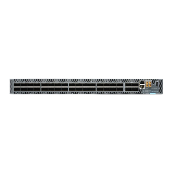
Management Port LEDs on ACX7100-32C Routers The ACX7100-32C has one management port that has separate LEDs to indicate link status and link activity. The port is located on the management panel and is labeled MGMT. Figure 5 on page 11 shows the location of the LEDs. - Page 20 ACX7100-32C router. Figure 6: ACX7100-32C Router Port Panel 100GbE ports (32 QSFP28 ports) 400GbE ports (4 QSFP56-DD ports) — — You can validate different port configurations on an ACX7100-32C by using the Port Checker Tool.
-
Page 21: Network Port Leds On Acx7100-32C Routers
Network Port LEDs on ACX7100-32C Routers Each ACX7100-32C network port uses a single bicolored LED to indicate link status, activity on the link, or a fault condition. Figure 7 on page 13 Figure 8 on page 13 show the location of the LEDs on an ACX7100-32C device. -
Page 22: Chassis Status Leds On Acx7100-32C Routers
On steadily All channels are down. Chassis Status LEDs on ACX7100-32C Routers The ACX7100-32C routers have four status LEDs that indicate the system status. You can find these LEDs to the right of the network ports (see Figure 9 on page 14). - Page 23 — Table 5 on page 15 describes the chassis status LEDs on ACX7100-32C routers, their colors and states, and the status that they indicate. You can view the colors of the three LEDs remotely through the CLI by issuing the operational mode command show chassis led.
- Page 24 (Continued) Table 5: Chassis Status LEDs on ACX7100-32C Routers Name Color State Description SYS—System LED Unlit The router is powered off or halted. Green On steadily Junos OS Evolved is loaded on the router. Blinking The device is loading the Software or the device is powering off.
-
Page 25: Cooling System And Airflow In Acx7100-32C Routers
IN THIS SECTION Fan Modules | 17 Fan Status LEDs on ACX7100-32C Routers | 20 The cooling system in ACX7100-32C routers consists of six fan modules and a single fan in each power supply module (PSM). Fan Modules The fan modules in ACX7100-32C routers are hot-insertable and hot-removable field-replaceable units (FRUs). - Page 26 Figure 10 on page 18 shows an ACX7100-32C fan module. Figure 10: Fan Module Used in ACX7100-32C Routers You remove and replace a fan module from the FRU end of the chassis. The router continues to operate for a limited period of time (240 seconds) during the replacement of the fan module without thermal shutdown.
- Page 27 AIR OUT labels. In data center deployments, position the router in such a manner that the AIR OUT labels on router components are facing the hot aisle. Figure 11: Air-Out (AO) Airflow Through ACX7100-32C Chassis...
- Page 28 You can check the status of the fan modules by using the show system alarms command or by examining the LEDs next to each fan module. On the ACX7100-32C routers, the fan module LEDs are located on the chassis next to the fan module slot.
-
Page 29: Acx7100-32C Power System
DC Power Supply Module LEDs on ACX7100-32C Routers | 28 AC Power Supply for ACX7100-32C Routers The ACX7100-32C AC router operates at 1600 W. The two power supply modules (PSMs) in ACX7100-32C routers are hot-removable and hot-insertable field-replaceable units (FRUs). The PSMs are preinstalled in the router. -
Page 30: Ac Power Specifications For Acx7100-32C Routers
— — AC inlet — Table 8 on page 22 lists the PSM and the direction of airflow. Table 8: Airflow Direction in AC PSMs for ACX7100-32C Power Supply Modules Wattage Direction of Airflow Color of Power Supply Module Handle... -
Page 31: Ac Power Cord Specifications For Acx7100-32C Routers
(Continued) Table 9: AC Power Specifications for ACX7100-32C Routers Item Specifications for ACX7100-32C AC input line frequency 50–60 Hz AC input current rating 11.5 A at 115-127 VAC 6.5 A at 200-240 VAC Typical power consumption (at 25°C ambient 500 W temperature and without optics) Maximum power consumption (at 40°C ambient... - Page 32 Table 10: AC Power Cord Specifications Country/Region Electrical Plug Standards Juniper Spare Juniper Graphic Specifications Model Model Number Number Argentina 250 VAC, 10 A, IRAM 2073 Type RA/3 – CBL-PWR- 50 Hz C15M- HITEMP-AR Australia 250 VAC, 10 A, AS/NZS 3112-2000...
-
Page 33: Ac Power Supply Module Leds On Acx7100-32C Routers
C15M- HITEMP-UK AC Power Supply Module LEDs on ACX7100-32C Routers The AC power supply module (PSM) on an ACX7100-32C router uses three LEDs to indicate power status. Figure 14 on page 25 shows the location of the LEDs on the AC PSM. -
Page 34: Dc Power Supply For Acx7100-32C Routers
(FRUs). The PSMs are preinstalled in the router. The DC power supply in ACX7100-32C is 1600 W with dual feeds for power resiliency. You can install replacement PSMs without powering off the router or disrupting the router function. -
Page 35: Dc Power Specifications For Acx7100-32C Routers
— — Handle — Table 12 on page 27 lists the PSM and the direction of airflow. Table 12: Airflow Direction in DC PSMs for ACX7100-32C Power Supply Module Number Wattage Direction of Airflow Color of Power Supply Module Handle... -
Page 36: Dc Power Supply Module Leds On Acx7100-32C Routers
DC Power Supply Module LEDs on ACX7100-32C Routers Figure 16 on page 28 shows the location of the LEDs on the DC power supply module (PSM). Figure 16: DC PSM LEDs on an ACX7100-32C Router Input LED (IN) Fault LED (!) —... - Page 37 Table 14: DC PSM LEDs on ACX7100-32C Routers Name Color State Description IN (input) Unlit There is no input power to the PSM. Green On steadily There is input DC power to the PSM. OUT (output) Unlit There is no output voltage from the PSM.
-
Page 38: Site Planning, Preparation, And Specifications
C HAPTER Site Planning, Preparation, and Specifications Site Preparation Checklist for ACX7100-32C Routers | 31 ACX7100-32C Site Guidelines and Requirements | 32 ACX7100-32C Network Cable and Transceiver Planning | 42 ACX7100-32C Management and Console Port Specifications and Pinouts | 55... -
Page 39: Site Preparation Checklist For Acx7100-32C Routers
Site Preparation Checklist for ACX7100-32C Routers The checklist in Table 15 on page 31 summarizes the tasks you need to perform when preparing a site for an ACX7100-32C router installation. Table 15: Site Preparation Checklist Item or Task For More Information... -
Page 40: Acx7100-32C Site Guidelines And Requirements
Plan the cable routing and management. ACX7100-32C Site Guidelines and Requirements IN THIS SECTION General Site Guidelines | 33 Site Electrical Wiring Guidelines | 33 Chassis Physical Specifications for ACX7100-32C Routers | 34... -
Page 41: General Site Guidelines
Environmental Requirements and Specifications for ACX7100-32C Routers | 35 Grounding Cable and Lug Specifications for ACX7100-32C | 36 Clearance Requirements for Hardware Maintenance of ACX7100-32C Routers | 38 Rack Requirements for ACX7100-32C Routers | 39 Cabinet Requirements for ACX7100-32C Routers | 40... -
Page 42: Chassis Physical Specifications For Acx7100-32C Routers
Electrical hazards as a result of power surges conducted over the lines into the equipment Chassis Physical Specifications for ACX7100-32C Routers The ACX7100-32C router chassis is a rigid sheet-metal structure that houses the hardware components. Table 17 on page 35 summarizes the physical specifications of an ACX7100-32C router and its components. -
Page 43: Environmental Requirements And Specifications For Acx7100-32C Routers
Table 17: Physical Specifications for an ACX7100-32C Router Chassis and FRUs Item Height Width Depth Weight ACX7100-32C 1.75 in. 17.36 in. Without fan module and • With FRUs installed: (4.45 cm) (44.09 cm) power supply module 28.58 lb (12.9 kg) (PSM) handles: 23.42 in. -
Page 44: Grounding Cable And Lug Specifications For Acx7100-32C
(EMI) requirements. To ground an ACX7100-32C router, connect a grounding cable to earth ground, and then attach the grounding cable to the chassis grounding points. - Page 45 • The grounding points are in the form of studs that are sized for #10-32 screws. You need to provide these screws with integrated washers as we do not ship them in the accessory kit. • For ACX7100-32C routers, the grounding lug required is a Panduit LCD10-10A-L or equivalent. The grounding lug accommodates 14–10 AWG (2–5.3mm²), stranded wire.
-
Page 46: Clearance Requirements For Hardware Maintenance Of Acx7100-32C Routers
• If you are mounting an ACX7100-32C router in a rack or cabinet that has other equipment installed, ensure that the exhaust from other equipment does not blow into the intake vents of the chassis. -
Page 47: Rack Requirements For Acx7100-32C Routers
(document number EIA-310–D) published by the Electronics Industry Association. Size, airflow, and • If you are mounting an ACX7100-32C flush with the front posts of a rack, ensure that clearance the distance between the front posts and the rear posts is between 23.2 in. (59 cm) and requirements 30.5 in. -
Page 48: Cabinet Requirements For Acx7100-32C Routers
Secure the rack to the ceiling brackets and to wall or floor brackets for maximum stability. Cabinet Requirements for ACX7100-32C Routers You can mount ACX7100-32C routers in a cabinet that contains a four-post 19-in. rack as defined in Cabinets, Racks, Panels, and Associated Equipment (document number EIA-310-D) published by the Electronics Industry Association. - Page 49 (document number EIA-310–D) published by the Electronics Industry Association. Size, airflow, • If you are mounting an ACX7100-32C flush with the front posts of a rack inside the cabinet, and clearance ensure that the distance between the front posts and the rear posts is between 23.2 in. (59 requirements cm) and 30.5 in.
-
Page 50: Acx7100-32C Network Cable And Transceiver Planning
You can find information about the pluggable transceivers and connector types that are supported on your Juniper Networks device by using the Hardware Compatibility Tool. The tool also documents the optical and cable characteristics, where applicable, for each transceiver. You can search for transceivers... -
Page 51: Cable And Connector Specifications For Acx7100-32C
The list of supported transceivers for the ACX7100-32C is located at https:/ / apps.juniper.net/hct/product/. CAUTION: If you face a problem running a Juniper Networks device that uses a third- party optic or cable, the Juniper Networks Technical Assistance Center (JTAC) can help you diagnose the source of the problem. - Page 52 12-Fiber MPO Connectors There are two types of cables used with 12-fiber MPO connectors on Juniper Networks devices—patch cables with MPO connectors on both ends, and breakout cables with an MPO connector on one end and four LC duplex connectors on the other end. Depending on the application, the cables might use single-mode fiber (SMF) or multimode fiber (MMF).
- Page 53 (Continued) Table 21: Cable Signals for 12-Fiber Ribbon Patch Cables Fiber Signal Unused Unused Unused Unused Rx3 (Receive) Rx2 (Receive) Rx1 (Receive) Rx0 (Receive) Table 22: Cable Pinouts for 12-Fiber Ribbon Patch Cables MPO Pin MPO Pin...
- Page 54 (Continued) Table 22: Cable Pinouts for 12-Fiber Ribbon Patch Cables MPO Pin MPO Pin 12-Fiber Ribbon Breakout Cables with MPO-to-LC Duplex Connectors You can use 12-fiber ribbon breakout cables with MPO-to-LC duplex connectors to connect a QSFP+ transceiver to four separate SFP+ transceivers—for example, 4x10GBASE-LR-to-10GBASE-LR, or 4x10GBASE-SR-to-10GBASE-SR SFP+ transceivers.
- Page 55 Rx on LC Duplex 1 12-Ribbon Patch and Breakout Cables Available from Juniper Networks Juniper Networks sells 12-ribbon patch and breakout cables with MPO connectors that meet the requirements described above. You are not required to purchase cables from Juniper Networks.
- Page 56 Table 24: 12-Ribbon Patch and Breakout Cables Available from Juniper Networks Cable Type Connector Type Fiber Type Cable Length Juniper Model Number 12-ribbon patch Socket MPO/PC to socket MPO/PC, MTP12-FF-M1M key up to key up (OM3) MTP12-FF-M3M MTP12-FF-M5M 10 m...
- Page 57 (Continued) Table 24: 12-Ribbon Patch and Breakout Cables Available from Juniper Networks Cable Type Connector Type Fiber Type Cable Length Juniper Model Number 10 m MTP-4LC-S10M 24-Fiber MPO Connectors You can use patch cables with 24-fiber MPO connectors to connect two supported transceivers of the same type—for example, 2x100GE-SR-to-2x100GE-SR.
- Page 58 Generic Requirements for Multi- The optical interface must meet the FT-1435-CORE requirement in Fiber Optical Connectors . The module must pass the wiggle test defined by IEC 62150-3. CS Connector You can use patch cables with CS connectors to connect two supported transceivers of the same type- for example, 2x100G-LR4 to 2x100G-LR4 or 2x100G-CWDM4 to 2x100G-CWDM4.
-
Page 59: Calculating Power Budget And Power Margin For Fiber-Optic Cables
TIP: You can use the Hardware Compatibility Tool to find information about the pluggable transceivers supported on your Juniper Networks device. To calculate the power budget and power margin, perform the following tasks: How to Calculate Power Budget for Fiber-Optic Cables To ensure that fiber-optic connections have sufficient power for correct operation, you need to calculate the link's power budget, which is the maximum amount of power it can transmit. - Page 60 – LL greater than zero indicates that the power budget is sufficient to operate the receiver. Factors that can cause link loss include higher-order mode losses, modal and chromatic dispersion, connectors, splices, and fiber attenuation. Table 25 on page 52 lists an estimated amount of loss for the factors used in the following sample calculations.
-
Page 61: Fiber-Optic Cable Signal Loss, Attenuation, And Dispersion
The following sample calculation for an 8-km-long single-mode link with a power budget (P ) of 13 dB uses the estimated values from Table 25 on page 52. This example calculates link loss (LL) as the sum of fiber attenuation (8 km @ 0.5 dB/km, or 4 dB) and loss for seven connectors (0.5 dB per connector, or 3.5 dB). - Page 62 The optical power budget must allow for the sum of component attenuation, power penalties (including those from dispersion), and a safety margin for unexpected losses. RELATED DOCUMENTATION ACX7100-32C System Overview | 2 Port Panel of ACX7100-32C Routers | 11...
-
Page 63: Acx7100-32C Management And Console Port Specifications And Pinouts
ACX7100-32C Management and Console Port Specifications and Pinouts IN THIS SECTION Management Cable Specifications for ACX7100 Routers | 55 Management Port Connector Pinout Information for ACX7100 | 55 Console Port Connector Pinout on ACX7100 Routers | 56 USB Port Specifications for ACX7100 | 57... -
Page 64: Console Port Connector Pinout On Acx7100 Routers
The port uses an autosensing RJ-45 connector to support a 10/100BASE-T connection. Table 27 on page 56 provides the pinout information for the RJ-45 connector for the management port. Table 27: Management Port Connector Pinout Information Description Direction TRP1+ Transmit/receive data pair 1 TRP1–... -
Page 65: Usb Port Specifications For Acx7100
DB-9 adapter supplied with the router and a USB to DB-9 plug adapter. You must provide the USB to DB-9 plug adapter. Table 28: Console Port and TOD Connector Pinouts for the ACX7100 Signal Description Not Connected DSR Output Data set ready TOD Output Time of Day (TOD) for Precision Time Protocol (PTP) applications. - Page 66 CAUTION: Remove the USB flash drive before upgrading Junos OS Evolved or rebooting an ACX7100. Failure to do so could cause the router to behave unpredictably. RELATED DOCUMENTATION Management Panel of ACX7100-32C Routers | 9...
-
Page 67: Initial Installation And Configuration
Initial Installation and Configuration ACX7100-32C Installation Overview | 60 Unpack and Mount an ACX7100-32C Router | 60 Connect ACX7100-32C to Power | 66 Connect ACX7100-32C to External Devices | 75 Perform Initial Software Configuration for the ACX7100-32C Routers | 78... -
Page 68: Acx7100-32C Installation Overview
Unpack an ACX7100-32C Router The ACX7100-32C router chassis is a rigid sheet-metal structure that houses the hardware components. An ACX7100-32C router is shipped in a cardboard carton, secured with foam packing material. The carton also contains an accessory box and quick start instructions. -
Page 69: Register Products-Mandatory To Validate Slas
Documentation roadmap card Register Products—Mandatory to Validate SLAs Register all new Juniper Networks hardware products and changes to an existing installed product using the Juniper Networks website. Registering products and changes to products activates your hardware replacement service-level agreements (SLAs). -
Page 70: Mount An Acx7100-32C Router In A Rack
Before You Begin Rack Installation | 62 Install an ACX7100-32C Router in a Rack | 63 You can mount an ACX7100-32C router on a rack using the mounting kit provided with the device. Before You Begin Rack Installation Before you begin mounting an ACX7100-32C router in the rack: Prevention of 1. -
Page 71: Install An Acx7100-32C Router In A Rack
Figure 21 on page 63). Figure 21: Install the Mounting Rails on an ACX7100-32C Router Using a Phillips (+) number 1 screwdriver, secure the mounting rails to the chassis using the mounting screws. With one person on each side, hold on to the bottom of the chassis, and carefully lift the chassis so... - Page 72 Carefully slide the chassis with the rails attached on to the rack rails (see Figure 22 on page 64). Figure 22: Install the ACX7100-32C Router in a Four-Post Rack Install mounting screws into each of the front-mounting bracket holes aligned with the rack, starting from the bottom, and tighten the screws.
- Page 73 The rear-mounting blades on each side of the chassis are movable. You can adjust the length of the blades according to the depth of the rack. Figure 24: Install the Rear-Mounting Blades on an ACX7100-32C Router Install mounting screws into each of the rear-mounting bracket holes aligned with the rack, starting from the bottom, and secure them tightly.
-
Page 74: Connect Acx7100-32C To Power
To meet safety and electromagnetic interference (EMI) requirements and to ensure proper operation, you must ground the router properly before connecting power. Before you connect earth ground to the protective earthing terminal of a ACX7100-32C router, ensure that a licensed electrician has attached an appropriate grounding lug to the grounding cable. - Page 75 Figure 26 on page 67 shows the grounding points on ACX7100-32C routers. Figure 26: Grounding Points on the ACX7100-32C Router Grounding points — The grounding points are in the form of studs that are sized for #10-32 screws. (You need to provide these screws with integrated washers as we do not ship them in the accessory kit).
-
Page 76: Connect Earth Ground To Dc Psm Protective Earthing Terminal
PSM. The minimum recommendations for the ACX7100-32C router are 14-10 AWG (2-5.3 mm²) standard wire. To ground the chassis using the protective earthing terminal on the DC PSM:... -
Page 77: Connect Ac Power To An Acx7100-32C Router
• Install the PSM in the chassis. The power supply module (PSM) in an ACX7100-32C router is a hot-removable and hot-insertable field- replaceable unit (FRU). You can remove and replace it without powering off the router or disrupting... - Page 78 NOTE: You must connect each PSM to a dedicated power source outlet. To connect AC power to an ACX7100-32C router: Wrap and fasten one end of the ESD grounding strap around your bare wrist, and connect the other end of the strap to the ESD point on the chassis.
-
Page 79: Connect Dc Power To An Acx7100-32C Router
11. Repeat Step through Step for the installing the remaining PSM. Figure 29: Connect an AC Power Cord to an ACX7100-32C Connect DC Power to an ACX7100-32C Router Before you begin connecting DC power to the router: • Ensure that you have taken the necessary precautions to prevent electrostatic discharge (ESD) - Page 80 • Phillips (+) screwdriver, number 2 (not provided) • Multimeter (not provided) The power supply module (PSM) in an ACX7100-32C router is a hot-removable and hot-insertable field- replaceable unit (FRU). You can remove and replace it without powering off the router or disrupting routing functions.
- Page 81 NOTE: Ring lug required is a KST P/N: RNYBS8-4 or equivalent (not provided). The ACX7100-32C router is designed to operate with a DC PSM that has a single, non-redundant, feed input. For source redundancy, you must install two DC PSMs in the ACX7100-32C; connect source (A) to one PSM and connect source (B) to the second PSM.
- Page 82 Junos OS software. In case of a system reboot failure, you need to power cycle the switch. To check the current FPGA version, issue the show chassis firmware command. Figure 30: Connect DC Power Cable to an ACX7100-32C Router RELATED DOCUMENTATION ACX7100-32C Power System | 21...
-
Page 83: Connect Acx7100-32C To External Devices
NOTE: If your laptop or PC does not have a DB-9 pin contact and you want to connect your laptop or PC directly to the ACX7100-32C router, use a combination of the RJ-45 cable and RJ-45 to DB-9 adapter supplied with the device and a USB to DB-9 plug adapter. You must provide the USB to DB-9 plug adapter. -
Page 84: Connect An Acx7100-32C Router To A Network For Out-Of-Band Management
"ACX7100-32C Network Cable and Transceiver Planning" on page You can monitor and manage the ACX7100-32C router by using a dedicated management channel. Use the management ports to connect the ACX7100-32C router to a network for out-of-band management. NOTE: You cannot use the management ports to perform the initial configuration of the ACX7100-32C router. -
Page 85: Connect An Acx7100-32C Router To External Clocking And Timing Devices
Connect an ACX7100-32C Router to External Clocking and Timing Devices The ACX7100-32C router has four SMB connector ports that support 1-PPS and 10-MHz timing devices. NOTE: Ensure that you use a cable of 3 m or less in length for the 10-MHz and 1-PPS connectors. -
Page 86: Perform Initial Software Configuration For The Acx7100-32C Routers
(CLI). Connect the console port on the ACX7100-32C to a laptop or desktop PC using the supplied RJ-45 cable and RJ-45 to DB-9 adapter. The console (CON) port is the lower RJ-45 port on the right side of the port panel. - Page 87 Stop the chassis auto-upgrade process [edit] root@# delete chassis auto-image-upgrade ZTP is enabled on the ACX7100-32C device in factory default configuration. You must stop ZTP before you proceed to configure any settings. [edit] root@# delete system commit factory-settings Add a password for the root administration user account.
- Page 88 12. Configure the IP address and prefix length for the management port on the router. On the ACX7100-32C, the management port is the upper RJ-45 port on the right side of the port panel and is labeled MGMT.
- Page 89 14. Enable Telnet service, if needed. [edit] root@# set system services telnet NOTE: When Telnet is enabled, you cannot log in to the ACX7100-32C through Telnet using root credentials. Root login is allowed only for SSH access. 15. Enable SSH service.
-
Page 90: Maintaining Components
Maintaining Components Maintaining the ACX7100-32C Fan Modules | 83 Maintaining the ACX7100-32C Power Supplies | 86 Maintain the ACX7100-32C Transceivers and Fiber-Optic Cables | 95 Maintaining SATA Solid State Drive in an ACX7100-32C | 104 Uninstall the ACX7100-32C Router | 108... -
Page 91: Maintaining The Acx7100-32C Fan Modules
Install a Fan Module in an ACX7100-32C Router | 84 Remove a Fan Module from an ACX7100-32C Router Before you remove a fan module from an ACX7100-32C router, ensure that you have taken the Prevention of Electrostatic necessary precautions to prevent electrostatic discharge (ESD) damage (see... -
Page 92: Install A Fan Module In An Acx7100-32C Router
Junos OS raises a major alarm. Install a Fan Module in an ACX7100-32C Router Before you install a fan module in an ACX7100-32C router, ensure that you have taken the necessary Prevention of Electrostatic Discharge precautions to prevent electrostatic discharge (ESD) damage (see... - Page 93 NOTE: The fan module provides port-to-FRU airflow (AO) or FRU-to-port (AI) airflow depending on the product model that you purchase. Ensure that you have the following parts and tools available to install a fan module in an ACX7100-32C router: • ESD grounding strap •...
-
Page 94: Maintaining The Acx7100-32C Power Supplies
4. Using a Phillips screwdriver, turn the locking screw until it is tight. Figure 35: Install a Fan Module in an ACX7100-32C Router RELATED DOCUMENTATION ACX7100-32C System Overview | 2 Cooling System and Airflow in ACX7100-32C Routers | 17 Maintaining the ACX7100-32C Power Supplies... -
Page 95: Replace An Acx7100-32C Ac Power Supply Module
• ESD grounding strap • Antistatic bag or an antistatic mat The power supply modules (PSMs) in an ACX7100-32C router are hot-removable and hot-insertable field-replaceable units (FRUs): you can remove and replace them without powering off the router or disrupting routing functions. -
Page 96: Install An Ac Power Supply Module In An Acx7100-32C Router
"Cooling System and Airflow in ACX7100-32C Routers" on page 17 for more information. The power supply modules (PSMs) in an ACX7100-32C router are hot-removable and hot-insertable field-replaceable units (FRUs): you can remove and replace them without powering off the router or disrupting routing functions. - Page 97 CAUTION: Verify that the direction of the arrow on the PSM handle matches the direction of airflow in the chassis. Ensure that each PSM you install in the chassis has the same airflow direction. If you install PSMs with two different airflow directions, Junos OS raises an alarm, and the status (ALM) LED blinks amber.
- Page 98 Figure 38: Install an AC Power Cord in an ACX7100-32C router NOTE: Each PSM must be connected to a dedicated power source outlet. NOTE: If you have a Juniper J-Care service contract, register any addition, change, or upgrade of hardware components at https:/ /www.juniper.net/customers/csc/management/...
-
Page 99: Replace An Acx7100-32C Dc Power Supply Module
Replace an ACX7100-32C DC Power Supply Module IN THIS SECTION Remove an ACX7100-32C DC Power Supply Module | 91 Install an ACX7100-32C DC Power Supply Module | 93 Remove an ACX7100-32C DC Power Supply Module Before you remove a power supply module (PSM), be aware of the following: NOTE: The minimum required number of PSMs must always be present in the router. - Page 100 Verify that the status LED on the PSM is not lit. Wrap and fasten one end of the ESD grounding strap around your bare wrist, and connect the other end of the strap to the ESD point on the chassis. Remove the clear plastic cover protecting the terminal studs on the faceplate.
-
Page 101: Install An Acx7100-32C Dc Power Supply Module
Install an ACX7100-32C DC Power Supply Module WARNING: Before performing DC power procedures, ensure that power is removed from the DC circuit. To ensure that all power is off, locate the circuit breaker on the panel board that services the DC circuit, switch the circuit breaker to the off position, and tape the switch handle of the circuit breaker in the off position. - Page 102 10. Observe the status LED on the power supply faceplate. If the PSM is correctly installed and functioning normally, the status LED lights green steadily. Figure 41: Install a DC PSM in an ACX7100-32C Router Figure 42: Connect the DC Power Cables...
-
Page 103: Maintain The Acx7100-32C Transceivers And Fiber-Optic Cables
• Rubber safety caps to cover the transceiver and fiber-optic cable connector • A dust cover to cover the port or a replacement transceiver The transceivers for Juniper Networks devices are hot-removable and hot-insertable field-replaceable units (FRUs): You can remove and replace them without powering off the device or disrupting device functions. - Page 104 2. Wrap and fasten one end of the ESD wrist strap around your bare wrist, and connect the other end of the strap to the ESD point on the switch. 3. Label the cable connected to the transceiver so that you can reconnect it correctly. LASER WARNING: Do not look directly into a fiber-optic transceiver or into the ends of fiber-optic cables.
-
Page 105: Install A Transceiver
b. Grasp the transceiver ejector lever and gently slide the transceiver approximately 0.5 in. (1.3 cm) straight out of the port. CAUTION: To prevent ESD damage to the transceiver, do not touch the connector pins at the end of the transceiver. Figure 43: Remove a QSFP+ Transceiver Ejector lever —... - Page 106 NOTE: We recommend that you use only optical transceivers and optical connectors purchased from Juniper Networks with your Juniper Networks device. CAUTION: If you face a problem running a Juniper Networks device that uses a third- party optic or cable, the Juniper Networks Technical Assistance Center (JTAC) can help you diagnose the source of the problem.
- Page 107 for at least 10 seconds after removing the transceiver from the port before installing a new transceiver. 5. Using both hands, carefully place the transceiver in the empty port. The connectors must face the chassis. CAUTION: Before you slide the transceiver into the port, ensure that the transceiver is aligned correctly.
-
Page 108: Remove A Qsfp28 Transceiver
• A dust cover to cover the port or a replacement transceiver The transceivers for Juniper Networks devices are hot-removable and hot-insertable field-replaceable units (FRUs). You can remove and replace them without powering off the device or disrupting the device... - Page 109 6 seconds for the interface to display operational commands. NOTE: We recommend that you use only optical transceivers and optical connectors purchased from Juniper Networks with your Juniper Networks device. To remove a QSFP28 transceiver (see Figure 45 on page 102): 1.
-
Page 110: Install A Qsfp28 Transceiver
Ensure that you have a rubber safety cap available to cover the transceiver. The transceivers for Juniper Networks devices are hot-removable and hot-insertable field-replaceable units (FRUs): You can remove and replace them without powering off the device or disrupting the device functions. - Page 111 CAUTION: If you face a problem running a Juniper Networks device that uses a third- party optic or cable, the Juniper Networks Technical Assistance Center (JTAC) can help you diagnose the source of the problem. Your JTAC engineer might recommend that you check the third-party optic or cable and potentially replace it with an equivalent Juniper Networks optic or cable that is qualified for the device.
-
Page 112: Maintaining Sata Solid State Drive In An Acx7100-32C
Maintaining SATA Solid State Drive in an ACX7100-32C IN THIS SECTION Removing a SATA Solid State Drive from an ACX7100-32C | 104 Installing a SATA Solid State Drive in an ACX7100-32C | 106 Removing a SATA Solid State Drive from an ACX7100-32C... - Page 113 • Phillips (+) screwdriver, number 1 The ACX7100-32C supports two 100 GB Serial Advanced Technology Attachment (SATA) solid state drives (SSD).The SSDs cannot be installed or removed when the system is up. You must shutdown the system before replacing the SSD. The SSDs are preinstalled in the ACX7100-32C.
-
Page 114: Installing A Sata Solid State Drive In An Acx7100-32C
6. Place the SSD cover plate back on the chassis and tighten the three captive screws securing the SSD cover plate. Installing a SATA Solid State Drive in an ACX7100-32C Before you install an SATA SSD in the device, ensure that you have taken the necessary precautions to... - Page 115 Ensure that you have the following parts and tools available to install an SATA SSD in the ACX7100-32C router: • ESD grounding strap • Antistatic bag or an antistatic mat • Phillips (+) screwdriver, number 1 1. Place the antistatic bag or the antistatic mat on a flat, stable surface.
-
Page 116: Uninstall The Acx7100-32C Router
Uninstall the ACX7100-32C Router IN THIS SECTION Power Off an ACX7100-32C Router | 108 Remove an ACX7100-32C Router from a Rack or Cabinet | 110 Power Off an ACX7100-32C Router Before you power off an ACX7100-32C router: • Ensure that you have taken the necessary precautions to prevent electrostatic discharge (ESD) Prevention of Electrostatic Discharge Damage damage. - Page 117 For instructions about connecting a management device to the management (MGMT) port, see "Connect an ACX7100-32C Router to a Network for Out-of-Band Management" on page 2. Shut down Junos OS from the external management device by issuing the request system halt operational mode CLI command.
-
Page 118: Remove An Acx7100-32C Router From A Rack Or Cabinet
• A Phillips (+) screwdriver, number 2 or number 3, depending on the size of your rack mounting screws. If you need to relocate an installed ACX7100-32C router, use the procedure described in this topic. NOTE: When you remove multiple devices from a rack, remove the device in the top of the rack first and proceed to remove the rest of the devices from top to bottom. - Page 119 • Ensure that you have disconnected any cables or wires attached to the router ports. To remove an ACX7100-32C router from a rack or cabinet: 1. Have one person support the weight of the router while another person uses the screwdriver to remove the front mounting screws that attach the chassis mounting rails to the rack or cabinet.
-
Page 120: Troubleshooting Hardware
C HAPTER Troubleshooting Hardware Troubleshooting the ACX7100-32C Router | 113... -
Page 121: Troubleshooting The Acx7100-32C Router
Troubleshooting the ACX7100-32C Router IN THIS SECTION Alarm Types and Severity Classes on ACX Series Routers | 113 Alarm Types and Severity Classes on ACX Series Routers IN THIS SECTION Alarm Types | 114 Alarm Severity Classes | 114 Before monitoring the alarms on the router, become familiar with the terms defined in Table 30 on page 113. -
Page 122: Contacting Customer Support And Returning The Chassis Or Components | 116
(Continued) Table 30: Alarm Terms Term Definition System alarm Predefined alarm that is triggered by a missing rescue configuration or failure to install a license for a licensed software feature. Alarm Types The router supports these alarms: • Chassis alarms indicate a failure on the router or one of its components. Chassis alarms are preset and cannot be modified. - Page 123 C HAPTER Contacting Customer Support and Returning the Chassis or Components Contacting Customer Support and Returning the Chassis or Components | 116...
-
Page 124: Contacting Customer Support And Returning The Chassis Or Components
NOTE: Do not return any component to Juniper Networks, Inc. unless you have first obtained an RMA number. Juniper Networks, Inc. reserves the right to refuse shipments that do not have an RMA. -
Page 125: How To Locate The Serial Number On An Acx7100-32C Router Or Component
If you are returning a router or component to Juniper Networks for repair or replacement, you must locate the serial number of the router or component. You must provide the serial number to the Juniper Networks Technical Assistance Center (JTAC) when you contact them to obtain a Return Materials Authorization (RMA). - Page 126 The show chassis hardware output for ACX7100-32C: user@device> show chassis hardware Hardware inventory: Item Version Part number Serial number Description Chassis YX0220330011 JNP7100-32C [ACX7100-32C] PSM 0 REV 04 740-085431 1ED79520069 JPSU-1600W-AC-AFO PSM 1 REV 04 740-085431 1ED79520159 JPSU-1600W-AC-AFO Routing Engine 0 REV 03...
-
Page 127: Locate The Chassis Serial Number Id Label On An Acx7100-32C Router
Locate the Chassis Serial Number ID Label on an ACX7100-32C Router On the ACX7100-32C router product models, the serial number ID label is located on top of the device and in a pull-out tab under the chassis status LEDs. See... -
Page 128: Locate The Serial Number Id Label On An Acx7100-32C Fan Module
Locate the Serial Number ID Label on an ACX7100-32C Fan Module The fan modules installed in an ACX7100-32C are field-replaceable units (FRUs). For each FRU, you must remove the FRU from the router chassis to see the FRU serial number ID label. -
Page 129: Contact Customer Support To Obtain Return Material Authorization
Figure 56: ACX7100-32C Fan Module Serial Number Location Contact Customer Support to Obtain Return Material Authorization If you are returning a device or hardware component to Juniper Networks for repair or replacement, obtain a Return Material Authorization (RMA) number from Juniper Networks Technical Assistance Center (JTAC). -
Page 130: Guidelines For Packing Hardware Components For Shipment
• Service Request Manager: https:/ /support.juniper.net/support • Telephone: +1-888-314-JTAC (+1-888-314-5822), toll free in U.S., Canada, and Mexico NOTE: For international or direct-dial options in countries without toll free numbers, see https:/ / support.juniper.net/support If you are contacting JTAC by telephone, enter your 12-digit service request number followed by the pound (#) key for an existing case, or press the star (*) key to be routed to the next available support engineer. -
Page 131: Safety And Compliance Information
C HAPTER Safety and Compliance Information General Safety Guidelines and Warnings | 125 Definitions of Safety Warning Levels | 126 Qualified Personnel Warning | 128 Warning Statement for Norway and Sweden | 128 Fire Safety Requirements | 129 Installation Instructions Warning | 130 Chassis and Component Lifting Guidelines | 131 Restricted Access Warning | 131 Ramp Warning | 133... - Page 132 DC Power Grounding Requirements and Warning | 155 DC Power Wiring Sequence Warning | 156 DC Power Wiring Terminations Warning | 158 Multiple Power Supplies Disconnection Warning | 159 TN Power Warning | 160 Action to Take After an Electrical Accident | 160 Agency Approvals for ACX7100 Routers | 161 Compliance Statements for Data Center | 163 Compliance Statements for EMC Requirements | 163...
-
Page 133: General Safety Guidelines And Warnings
General Safety Guidelines and Warnings The following guidelines help ensure your safety and protect the device from damage. The list of guidelines might not address all potentially hazardous situations in your working environment, so be alert and exercise good judgment at all times. •... -
Page 134: Definitions Of Safety Warning Levels
• Some parts of the chassis, including AC and DC power supply surfaces, power supply unit handles, SFB card handles, and fan tray handles might become hot. The following label provides the warning for hot surfaces on the chassis: • Always ensure that all modules, power supplies, and cover panels are fully inserted and that the installation screws are fully tightened. - Page 135 Waarschuwing Dit waarschuwingssymbool betekent gevaar. U verkeert in een situatie die lichamelijk letsel kan veroorzaken. Voordat u aan enige apparatuur gaat werken, dient u zich bewust te zijn van de bij elektrische schakelingen betrokken risico's en dient u op de hoogte te zijn van standaard maatregelen om ongelukken te voorkomen. Varoitus Tämä...
-
Page 136: Qualified Personnel Warning
Qualified Personnel Warning WARNING: Only trained and qualified personnel should install or replace the device. Waarschuwing Installatie en reparaties mogen uitsluitend door getraind en bevoegd personeel uitgevoerd worden. Varoitus Ainoastaan koulutettu ja pätevä henkilökunta saa asentaa tai vaihtaa tämän laitteen. Avertissement Tout installation ou remplacement de l'appareil doit être réalisé... -
Page 137: Fire Safety Requirements
In addition, you should establish procedures to protect your equipment in the event of a fire emergency. Juniper Networks products should be installed in an environment suitable for electronic equipment. We recommend that fire suppression equipment be available in the event of a fire in the vicinity of the equipment and that all local fire, safety, and electrical codes and ordinances be observed when you install and operate your equipment. -
Page 138: Installation Instructions Warning
NOTE: To keep warranties effective, do not use a dry chemical fire extinguisher to control a fire at or near a Juniper Networks device. If a dry chemical fire extinguisher is used, the unit is no longer eligible for coverage under a service agreement. -
Page 139: Chassis And Component Lifting Guidelines
Chassis and Component Lifting Guidelines • Before moving the device to a site, ensure that the site meets the power, environmental, and clearance requirements. • Before lifting or moving the device, disconnect all external cables and wires. • As when lifting any heavy object, ensure that your legs bear most of the weight rather than your back. - Page 140 Avertissement Cet appareil est à installer dans des zones d'accès réservé. Ces dernières sont des zones auxquelles seul le personnel de service peut accéder en utilisant un outil spécial, un mécanisme de verrouillage et une clé, ou tout autre moyen de sécurité. L'accès aux zones de sécurité...
-
Page 141: Ramp Warning
Ramp Warning WARNING: When installing the device, do not use a ramp inclined at more than 10 degrees. Waarschuwing Gebruik een oprijplaat niet onder een hoek van meer dan 10 graden. Varoitus Älä käytä sellaista kaltevaa pintaa, jonka kaltevuus ylittää 10 astetta. Avertissement Ne pas utiliser une rampe dont l'inclinaison est supérieure à... - Page 142 Les directives ci-dessous sont destinées à assurer la protection du personnel: • Le rack sur lequel est monté le Juniper Networks switch doit être fixé à la structure du bâtiment.
- Page 143 Le seguenti direttive vengono fornite per garantire la sicurezza personale: • Il Juniper Networks switch deve essere installato in un telaio, il quale deve essere fissato alla struttura dell'edificio. • Questa unità deve venire montata sul fondo del supporto, se si tratta dell'unica unità...
- Page 144 Para garantizar su seguridad, proceda según las siguientes instrucciones: • El Juniper Networks switch debe instalarse en un bastidor fijado a la estructura del edificio. • Colocar el equipo en la parte inferior del bastidor, cuando sea la única unidad en el...
-
Page 145: Grounded Equipment Warning
Följande riktlinjer ges för att trygga din säkerhet: • Juniper Networks switch måste installeras i en ställning som är förankrad i byggnadens struktur. • Om denna enhet är den enda enheten på ställningen skall den installeras längst ned på... -
Page 146: Radiation From Open Port Apertures Warning
Avvertenza Questo dispositivo deve sempre disporre di una connessione a massa. Seguire le istruzioni indicate in questa guida per connettere correttamente il dispositivo a massa. Advarsel Denne enheten på jordes skikkelig hele tiden. Følg instruksjonene i denne veiledningen for å jorde enheten. Aviso Este equipamento deverá... -
Page 147: Laser And Led Safety Guidelines And Warnings
Class 1 LED Product Warning | 141 Laser Beam Warning | 141 Juniper Networks devices are equipped with laser transmitters, which are considered a Class 1 Laser Product by the U.S. Food and Drug Administration and are evaluated as a Class 1 Laser Product per IEC/EN 60825-1 requirements. - Page 148 General Laser Safety Guidelines When working around ports that support optical transceivers, observe the following safety guidelines to prevent eye injury: • Do not look into unterminated ports or at fibers that connect to unknown sources. • Do not examine unterminated optical ports with optical instruments. •...
- Page 149 Class 1 LED Product Warning LASER WARNING: Class 1 LED product. Waarschuwing Klasse 1 LED-product. Varoitus Luokan 1 valodiodituote. Avertissement Alarme de produit LED Class I. Warnung Class 1 LED-Produktwarnung. Avvertenza Avvertenza prodotto LED di Classe 1. Advarsel LED-produkt i klasse 1. Aviso Produto de classe 1 com LED.
-
Page 150: Maintenance And Operational Safety Guidelines And Warnings
Aviso Não olhe fixamente para o raio, nem olhe para ele directamente com instrumentos ópticos. ¡Atención! No mirar fijamente el haz ni observarlo directamente con instrumentos ópticos. Varning! Rikta inte blicken in mot strålen och titta inte direkt på den genom optiska instrument. - Page 151 aanbevolen is. Gebruikte batterijen dienen overeenkomstig fabrieksvoorschriften weggeworpen te worden. Varoitus Räjähdyksen vaara, jos akku on vaihdettu väärään akkuun. Käytä vaihtamiseen ainoastaan saman- tai vastaavantyyppistä akkua, joka on valmistajan suosittelema. Hävitä käytetyt akut valmistajan ohjeiden mukaan. Avertissement Danger d'explosion si la pile n'est pas remplacée correctement. Ne la remplacer que par une pile de type semblable ou équivalent, recommandée par le fabricant.
- Page 152 Waarschuwing Alvorens aan apparatuur te werken die met elektrische leidingen is verbonden, sieraden (inclusief ringen, kettingen en horloges) verwijderen. Metalen voorwerpen worden warm wanneer ze met stroom en aarde zijn verbonden, en kunnen ernstige brandwonden veroorzaken of het metalen voorwerp aan de aansluitklemmen lassen.
- Page 153 Varning! Tag av alla smycken (inklusive ringar, halsband och armbandsur) innan du arbetar på utrustning som är kopplad till kraftledningar. Metallobjekt hettas upp när de kopplas ihop med ström och jord och kan förorsaka allvarliga brännskador; metallobjekt kan också sammansvetsas med kontakterna. Lightning Activity Warning WARNING: Do not work on the system or connect or disconnect cables during periods of lightning activity.
- Page 154 6 in. (15.2 cm) of clearance around the ventilation openings. Waarschuwing Om te voorkomen dat welke switch van de Juniper Networks router dan ook oververhit raakt, dient u deze niet te bedienen op een plaats waar de maximale aanbevolen omgevingstemperatuur van 40°...
- Page 155 ¡Atención! Para impedir que un encaminador de la serie Juniper Networks switch se recaliente, no lo haga funcionar en un área en la que se supere la temperatura ambiente máxima recomendada de 40° C. Para impedir la restricción de la entrada de aire, deje un espacio mínimo de 15,2 cm alrededor de las aperturas para ventilación.
-
Page 156: General Electrical Safety Guidelines And Warnings
General Electrical Safety Guidelines and Warnings WARNING: Certain ports on the device are designed for use as intrabuilding (within- GR-1089-CORE ) the-building) interfaces only (Type 2 or Type 4 ports as described in and require isolation from the exposed outside plant (OSP) cabling. To comply with NEBS (Network Equipment-Building System) requirements and protect against lightning must not be surges and commercial power disturbances, the intrabuilding ports... -
Page 157: Prevention Of Electrostatic Discharge Damage
• Canada—Canadian Electrical Code, Part 1, CSA C22.1. • Suitable for installation in Information Technology Rooms in accordance with Article 645 of the National Electrical Code and NFPA 75. Peut être installé dans des salles de matériel de traitement de l’information conformément à l’article 645 du National Electrical Code et à... - Page 158 If a grounding strap is not available, hold the component in its antistatic bag (see Figure 57 on page 150) in one hand and touch the exposed, bare metal of the device with the other hand immediately before inserting the component into the device. WARNING: For safety, periodically check the resistance value of the ESD grounding strap.
-
Page 159: Site Electrical Wiring Guidelines
CAUTION: ANSI/TIA/EIA-568 cables such as Category 5e and Category 6 can get electrostatically charged. To dissipate this charge, always ground the cables to a suitable and safe earth ground before connecting them to the system. Attention Les câbles ANSI/TIA/EIA-568, par exemple Cat 5e et Cat 6, peuvent emmagasiner des charges électrostatiques. -
Page 160: Ac Power Electrical Safety Guidelines
(Continued) Table 31: Site Electrical Wiring Guidelines Site Wiring Guidelines Factor Radio To reduce or eliminate RFI from your site wiring, do the following: frequency • Use a twisted-pair cable with a good distribution of grounding conductors. interference • If you must exceed the recommended distances, use a high-quality twisted-pair cable with one ground conductor for each data signal, when applicable. -
Page 161: Ac Power Disconnection Warning
• The power cord serves as the main disconnecting device for the AC-powered device. The socket outlet must be near the AC-powered device and be easily accessible. • For devices that have more than one power supply connection, you must ensure that all power connections are fully disconnected so that power to the device is completely removed to prevent electric shock. -
Page 162: Dc Power Disconnection Warning
Aviso Antes de trabalhar num chassis, ou antes de trabalhar perto de unidades de fornecimento de energia, desligue o cabo de alimentação nas unidades de corrente alternada. ¡Atención! Antes de manipular el chasis de un equipo o trabajar cerca de una fuente de alimentación, desenchufar el cable de alimentación en los equipos de corriente alterna (CA). -
Page 163: Dc Power Grounding Requirements And Warning
Gleichstromschaltung ausfindig, stellen Sie den Unterbrecher auf AUS, und kleben Sie den Schaltergriff des Unterbrechers mit Klebeband in der AUS-Stellung fest. Avvertenza Prima di svolgere una qualsiasi delle procedure seguenti, verificare che il circuito CC non sia alimentato. Per verificare che tutta l'alimentazione sia scollegata (OFF), individuare l'interruttore automatico sul quadro strumenti che alimenta il circuito CC, mettere l'interruttore in posizione OFF e fissarlo con nastro adesivo in tale posizione. -
Page 164: Dc Power Wiring Sequence Warning
WARNING: When you install the device, the ground connection must always be made first and disconnected last. Waarschuwing Bij de installatie van het toestel moet de aardverbinding altijd het eerste worden gemaakt en het laatste worden losgemaakt. Varoitus Laitetta asennettaessa on maahan yhdistäminen aina tehtävä ensiksi ja maadoituksen irti kytkeminen viimeiseksi. - Page 165 Varoitus Oikea yhdistettava kytkentajarjestys on maajohto maajohtoon, +RTN varten +RTN, –48 V varten – 48 V. Oikea irrotettava kytkentajarjestys on –48 V varten – 48 V, +RTN varten +RTN, maajohto maajohtoon. Avertissement Câblez l'approvisionnement d'alimentation CC En utilisant les crochets appropriés à...
-
Page 166: Dc Power Wiring Terminations Warning
Varning! Korrekt kopplingssekvens ar jord till jord, +RTN till +RTN, –48 V till –48 V. Korrekt kopplas kopplingssekvens ar –48 V till –48 V, +RTN till +RTN, jord till jord. DC Power Wiring Terminations Warning WARNING: When stranded wiring is required, use approved wiring terminations, such as closed-loop or spade-type with upturned lugs. -
Page 167: Multiple Power Supplies Disconnection Warning
Aviso Quando forem requeridas montagens de instalação eléctrica de cabo torcido, use terminações de cabo aprovadas, tais como, terminações de cabo em circuito fechado e planas com terminais de orelha voltados para cima. Estas terminações de cabo deverão ser do tamanho apropriado para os respectivos cabos, e deverão prender simultaneamente o isolamento e o fio condutor. -
Page 168: Tn Power Warning
Aviso Este dispositivo possui mais do que uma conexão de fonte de alimentação de energia; para poder remover a fonte de alimentação de energia, deverão ser desconectadas todas as conexões existentes. ¡Atención! Esta unidad tiene más de una conexión de suministros de alimentación; para eliminar la alimentación por completo, deben desconectarse completamente todas las conexiones. -
Page 169: Agency Approvals For Acx7100 Routers
1. Use caution. Be aware of potentially hazardous conditions that could cause further injury. 2. Disconnect power from the device. 3. If possible, send another person to get medical aid. Otherwise, assess the condition of the victim, and then call for help. Agency Approvals for ACX7100 Routers IN THIS SECTION Compliance Statement for Argentina | 163... - Page 170 • FCC 47 CFR Part 15 Class A USA Radiated and Conducted Emissions • EN 55032 Class A European Radiated and Conducted Emissions • AS/NZS CISPR 32 Class A Australia/New Zealand Radiated and Conducted Emissions • ICES-003 Class A Canada Radiated and Conducted Emissions •...
-
Page 171: Compliance Statements For Data Center
• AT&T TEER (ATIS-06000015.03.2013) • ECR 3.0.1 • ETSI ES 203 136 (2013-05) • Verizon TEEER (VZ.TPR.9205 Issue 6) • Amazon Customer Requirements Compliance Statement for Argentina EQUIPO DE USO IDÓNEO. Compliance Statements for Data Center • The equipment is suitable for installation as part of the Common Bonding Network (CBN). •... - Page 172 Japan | 164 United States | 165 Canada CAN ICES-3 (A)/NMB-3(A) European Community This is a Class A product. In a domestic environment, this product might cause radio interference in which case the user might be required to take adequate measures. Israel Translation from Hebrew—Warning: This product is Class A.
-
Page 173: Compliance Statements For Environmental Requirements
The preceding translates as follows: This is a Class A product based on the standard of the Voluntary Control Council for Interference by Information Technology Equipment (VCCI). If this product is used near a radio or television receiver in a domestic environment, it might cause radio interference.
Need help?
Do you have a question about the ACX7100-32C and is the answer not in the manual?
Questions and answers