Table of Contents
Advertisement
Quick Links
Advertisement
Table of Contents

Related Manuals for Juniper ACX7348


Summary of Contents for Juniper ACX7348
- Page 1 ACX7348 Cloud Metro Router Hardware Guide Published 2023-12-18...
- Page 2 The Juniper Networks product that is the subject of this technical documentation consists of (or is intended for use with) Juniper Networks software. Use of such software is subject to the terms and conditions of the End User License Agreement ("EULA") posted at https:/ /support.juniper.net/support/eula/.
-
Page 3: Table Of Contents
ACX7348 System Software Overview | 10 ACX7348 Chassis | 10 ACX7348 Chassis Description | 10 ACX7348 Physical Specifications | 15 Cooling System and Airflow in ACX7348 Routers | 16 Fan Trays | 17 Fan Status LEDs | 17 Airflow | 19... - Page 4 Site Electrical Wiring Guidelines | 44 ACX7348 Grounding Cable and Lug Specifications | 46 Clearance Requirements for Airflow and Hardware Maintenance of ACX7348 Routers | 47 ACX7348 Rack and Cabinet Requirements | 48 Rack Requirements for ACX7348 Routers | 48...
- Page 5 Connect ACX7348 to External Devices | 87 Connect an ACX7348 Router to a Management Console | 87 Connect an ACX7348 Router to a Network for Out-of-Band Management | 88 Connect to 1-PPS and 10-MHz Timing Devices | 89 Connect an ACX7348 Router to a GNSS Antenna | 90...
- Page 6 Returning an ACX7348 Chassis or Components | 129 How to Return a Hardware Component to Juniper Networks, Inc. | 129 How to Locate the Serial Number on an ACX7348 Router or Component | 130 List the Chassis and Component Details Using the CLI | 131...
- Page 7 Compliance Standards for ACX7348 Routers | 140...
-
Page 8: About This Guide
About This Guide Use this guide to install hardware and perform initial software configuration, routine maintenance, and troubleshooting for the ACX7348 Cloud Metro Router. After completing the installation and basic configuration procedures covered in this guide, refer to the Junos OS Evolved... -
Page 9: Fast Track: Initial Installation
C HAPTER Fast Track: Initial Installation Fast Track to Rack Installation and Power | 2... -
Page 10: Fast Track To Rack Installation And Power
ACX7348 in a Rack" on page 72 Install the ACX7348 in a Rack You can install an ACX7348 router into a two-post rack, four-post rack, or a cabinet. We’ll walk you through the steps to install an AC-powered ACX7348 router in a two-post rack. -
Page 11: Connect To Power
4. Ensure that the chassis is level by verifying that all screws on one side of the rack align with the screws on the other side. Connect to Power IN THIS SECTION Ground the ACX7348 Router | 4 Connect the Power Cord and Power On the Router | 4... - Page 12 To connect the ACX7348 router to AC power, you must do the following: Ground the ACX7348 Router To connect AC power to an ACX7348 router: 1. Verify that a licensed electrician has attached the cable lug that is provided with the router to the grounding cable.
- Page 13 Connect the power cord to the power source outlet. NOTE: Each power supply module (PSM) must be connected to a dedicated AC power feed and a dedicated customer-site 2-pole circuit breaker. We recommend that you use a dedicated customer-site circuit breaker rated for 16 A, 250 VAC or as required by local code.
-
Page 14: Overview
C HAPTER Overview ACX7348 System Overview | 7 ACX7348 Chassis | 10 Cooling System and Airflow in ACX7348 Routers | 16 ACX7348 Power System | 21 ACX7348 Routing Engine | 31 ACX7300 Flexible PIC Concentrators | 36... -
Page 15: Acx7348 System Overview
ACX7348 System Software Overview | 10 ACX7348 Router Description The Juniper Networks® ACX7348 Cloud Metro Router is a multiservice platform from the ACX7300 series that addresses the growing demands of metro applications. With a compact 3-U semi-fixed form factor, this industrial-rated router offers an aggregation solution that gives cloud providers and service providers the performance and scalability needed as networks grow. -
Page 16: Benefits Of Acx7348 Routers
Field-replaceable units (FRUs) are router components you can replace at the customer site. Replacing most FRUs requires minimal router downtime. The ACX7348 router uses the following types of FRUs: • Hot-insertable and hot-removable—You can remove and replace these components without powering off the router or disrupting the routing function. -
Page 17: Acx7348 Router Component Redundancy
(FRUs). One Routing Engine functions as the primary and the other functions as the backup. • Power supply modules (PSMs)—You can install up to two PSMs on ACX7348 routers to provide full power, 1+1 redundancy to the device. Each PSM provides power to all components in the router. If one PSM fails, or if you remove one PSM, the second PSM balances the electrical load without interruption. -
Page 18: Acx7348 System Software Overview
ACX7348 System Software Overview The ACX7348 router runs Junos OS Evolved, which provides Layer 2 and Layer 3 switching, routing, and security services. Junos OS Evolved runs natively on Linux and has direct access to all Linux utilities and operations. It has a modular design that supports upgrades on a component-by-component basis without a system reboot. - Page 19 800 mm deep open rack, 19 in. equipment racks, or telco open-frame racks. For more information about the physical specifications of the router and its components, see Table 5 on page Figure 2: Front View of an AC-Powered ACX7348 Router ACX7300-FPC-2CD4C FPC Routing Engine —...
- Page 20 Fan Tray LEDs — Fixed FPC The ACX7348 router has a fixed flexible PIC concentrators (FPC) that has 48 SFP28 ports with MACsec capabilities and 8 QSFP28 ports. Table 2 on page 12 shows the port speeds supported on the fixed FPC.
- Page 21 NOTE: Each 100GbE port supports 4x25GbE breakout option System LED on the Front Panel One bicolor LED below the device label (ACX7348) indicates the status of the router. Table 3 on page describes the system LED in more detail. Table 3: System LED on the Front Panel...
- Page 22 The clocking port synchronizes clock inputs based on the clock’s priority. • PPS—1-pulse per second (PPS) output connector for connecting to external clock signal sources. The clocking port synchronizes clock inputs based on the clock’s priority. Table 4: Timing Ports LEDs on the ACX7348 Chassis Color State...
-
Page 23: Acx7348 Physical Specifications
(Continued) Table 4: Timing Ports LEDs on the ACX7348 Chassis Color State Description BITS Green On steadily Clock is active. Yellow On steadily Loss of clock. ACX7348 Physical Specifications Table 5: ACX7348 Router Chassis and Component Physical Specifications Description Weight... -
Page 24: Cooling System And Airflow In Acx7348 Routers
Table 5: ACX7348 Router Chassis and Component Physical Specifications (Continued) Description Weight Height Width Depth FPC Blank 0.54 lb (0.24 kg) 1.65 in. (4.19 cm) 5.40 in. (13.71 cm) 2.95 in. (7.49 cm) Cooling System and Airflow in ACX7348 Routers... -
Page 25: Fan Trays
Figure 6: Fan Tray 1. Fan tray ejector lever NOTE: The ACX7348 router must operate with all the four fan trays installed. If you need to replace a faulty fan tray, you must replace the fan tray within three minutes. - Page 26 Figure 7: Fan Status LEDs on the Front of the Router Figure 8: Fan Status LEDs on the Rear of the Router Fan tray Two-hole protective grounding terminal — — Fan tray LEDs — Table 6 on page 18 describes the behavior of the fan LED. Table 6: Fan Status LEDs Label Color...
-
Page 27: Airflow
(Continued) Table 6: Fan Status LEDs Label Color State Description On steadily Software initialization is complete, and the fan is functioning normally. Yellow On steadily Equipment is faulty and malfunctioning. Dark Fan tray input power failure Airflow The router has a front-to-back (AIR OUT) cooling system (see Figure 9 on page 20). -
Page 28: Air Filter Unit
Figure 9: Airflow Through the Chassis Air Filter Unit The air filter unit consists of four parts: the outer filter cover, the air filter, the inner cage, and the side brushes. The air filter sits right inside the outer filter cover and the inner cage. The air filter unit is installed in the front of the chassis and is secured to the rack rails by captive screws. -
Page 29: Power Supply Cooling System
The power supply modules (PSMs) are self-cooling and located in the front of the router. Each PSM has its own fan and is cooled by its own internal cooling system. The PSMs in an ACX7348 router support back-to-front airflow (airflow in or AFI). -
Page 30: Acx7348 Ac Power Supply Module Description
The ACX7348 router is powered by 2200 W hot-removable and hot-insertable pre-installed AC or DC power supply modules (PSMs). You can install two PSMs on ACX7348 routers to provide full power redundancy to the device. Each PSM provides power to all the components in the router. If one PSM fails, or if you remove one PSM, the second PSM balances the electrical load without interruption. - Page 31 (48x1.5W SFP+ optics and 8x5W QSFP28 optics) AC Power Supply Module LEDs on ACX7348 Routers The AC power supply module (PSM) on an ACX7348 router uses a single LED to indicate power status. Figure 12 on page 24 shows the AC PSM components along with the status LED.
- Page 32 — — Ejector lever Handle — — Table 8: AC PSM LEDs on ACX7348 Routers LED Color Power Supply State The PSM does not have AC power. Solid green The PSM is on and in the OK state. Blinking green The PSM is in standby state or other PSM in chassis is ON with 12VSB (vestigial sideband).
- Page 33 ACX7348 AC Power Cord Specifications Detachable AC power cords are shipped with the AC power supply modules. The plug end of the power cord fits into the power source outlet that is standard for your geographical location. Table 9: AC Power Cord Specifications...
- Page 34 (Continued) Table 9: AC Power Cord Specifications Country/Region Electrical Plug Standards Juniper Model Graphic Specifications Number India 250 AC, 16 A, 85 °C IS 1293 CBL-ACX-PWR- C19-IN Israel 250 AC, 16 A, SI 32 CBL-ACX-PWR- -40 °C to 70 °C...
-
Page 35: Acx7348 Dc Power Supply Module Description
ACX7348 DC Power Supply Module Description IN THIS SECTION ACX7348 Input DC Voltage Specification | 28 DC Power Supply Module LEDs on ACX7348 Routers | 28 ACX7348 DC Power Cables | 30 ACX7348 DC Power Cable Lugs | 30 Each 2200 W DC power supply module (PSM) has a single DC input and provides 12 V power to the system. - Page 36 + optics and 8x5W QSFP28 optics) DC Power Supply Module LEDs on ACX7348 Routers The DC power supply module (PSM) on an ACX7348 router uses a single LED to indicate power status. Figure 14 on page 29 shows the DC PSM components along with the status LED.
- Page 37 — — Ejector lever Handle — — Table 11: DC PSM LEDs on ACX7348 Routers LED Color Power Supply State The power supplies do not have DC power. Solid green The PSM is ON and in the OK state. Blinking green The PSM is in standby state or other PSM in chassis is ON with 12VSB (vestigial sideband).
- Page 38 ACX7348 DC Power Cable Lugs The accessory box shipped with the ACX7348 router includes the cable lugs that attach to the terminal studs of each PSM. Figure 15 on page 31...
-
Page 39: Acx7348 Routing Engine
Figure 15: ACX7348 DC Power Cable Lugs CAUTION: Before you begin to install the ACX7348 router, have a licensed electrician attach a cable lug to the power cables that you supply. A cable with an incorrectly attached lug can damage the ACX7348 router. - Page 40 Routing Engine LEDs | 34 The ACX7348 Routing Engine provides control plane and chassis management functions. The Routing Engine provides high-performance compute horsepower and memory and storage infrastructure that enables the operating system to run. You can install one or two Routing Engines on the router. A redundant system hosts two Routing Engines, one being the primary and the other, the backup.
- Page 41 Description Value Weight 2.14 lbs (0.97 kg) Routing Engine Front Panel Figure 17 on page 33 shows the front panel of the ACX7348 Routing Engine. Figure 17: ACX7348 Routing Engine Front Panel USB port ACT LED — — Management (MGMT) port ALM LED —...
- Page 42 • Green (steady) when the 1000-Mbps link is up. • Orange (steady) when the 100-Mbps link is up. • Off when the link is down. • Off and ACT LED is Yellow (blinking) when the 10-Mbps link is up. The activity LED is: •...
- Page 43 Table 13: ACX7300 Routing Engine LEDs Color State Description Green On steadily The Routing Engine is receiving adequate power. Blinking The Routing Engine is powered on but it has encountered a fault condition. Dark Power is disabled. Green On steadily The software is loaded and the Routing Engine is online.
-
Page 44: Acx7300 Flexible Pic Concentrators
FPC LEDs | 40 supported port speeds. The ACX7348 router supports the ACX7K3-FPC-2CD4C Flexible PIC Concentrators (FPC) that is installed horizontally in the front of the chassis. You can install the FPC into any of the three FPC slots on the ACX7348 chassis. -
Page 45: Acx7K3-Fpc-2Cd4C
Figure 18: ACX7K3-FPC-2CD4C ACX7K3-FPC-2CD4C Figure 19 on page 37 shows the front panel of the ACX7K3-FPC-2CD4C FPC. Figure 19: ACX7K3-FPC-2CD4C Front Panel PWR LED Ejecter lever — — STS LED 400GbE and 100GbE ports — — Port LEDs Online/Offline button —... - Page 46 You can use this button to power off or switch on the FPC. button Cables and You can use the Hardware Compatibility Tool to find information about the pluggable connectors transceivers supported on your Juniper Networks device. Table 15 on page 39 summarizes the port speed capability of ACX7K3-FPC-2CD4C.
- Page 47 Table 15: ACX7K3-FPC-2CD4C Port Speed FPC Slot Port Number Supported port speeds FPC 1 and FPC 2 Port 0 and Port 2 Each port supports the following port speeds: • 1x400G • 4x100G • 2x100G • 1x100G • 4x25G • 1x40G •...
-
Page 48: Fpc Leds
(Continued) Table 15: ACX7K3-FPC-2CD4C Port Speed FPC Slot Port Number Supported port speeds Each port supports the following FPC 3 Port 0, Port 1, Port 2 port speeds: • 1x100G • 1x40G • 4x25G • 4x10G NOTE: Ports 3, 4, and 5 are unused in FPC slot 3. - Page 49 (Continued) Table 16: FPC Status LEDs Color State Description Unlit The FPC is disabled or offline. Table 17 on page 41 describes the network port LEDs. Table 17: Network LEDs Color State Description Unlit A transceiver is not present in the port, or the link is down because of signal loss.
-
Page 50: Site Planning, Preparation, And Specifications
C HAPTER Site Planning, Preparation, and Specifications ACX7348 Site Guidelines and Requirements | 43 ACX7348 Rack and Cabinet Requirements | 48 ACX7348 Network Cable and Transceiver Planning | 51 ACX7348 Management and Console Port Specifications and Pinouts | 66... -
Page 51: Acx7348 Site Guidelines And Requirements
ACX7348 Site Guidelines and Requirements IN THIS SECTION SUMMARY Environmental Requirements and The proper function of the ACX7348 router depends Specifications for ACX7348 Routers | 43 on you meeting certain environmental requirements, following site and wiring guidelines, and ensuring General Site Guidelines | 44... -
Page 52: General Site Guidelines
Table 18: ACX7348 Router Environmental Tolerances Description Tolerance Altitude 6000 ft (1828 m) Relative operating humidity 5% to 90% (noncondensing) Operating temperature –40°F (–40°C) through 149°F (65°C), 1°C derating for every 1000 ft NOTE: With average IMIX packet size greater than 1000 bytes Shipping and storage temperature -40°... - Page 53 WARNING: You must provide a properly grounded and shielded environment and use electrical surge-suppression devices. Avertissement Vous devez établir un environnement protégé et convenablement mis à la terre et utiliser des dispositifs de parasurtension. Table 19: Site Electrical Wiring Guidelines Site Wiring Guidelines Factor...
-
Page 54: Acx7348 Grounding Cable And Lug Specifications
NOTE: You must ensure that all cables are rated for the environment in which they are deployed. For an ACX7348 router, you need a grounding cable and an LCD6-14A-L lug (see Figure 20 on page 46. The grounding lug accommodates a 6 AWG , 90° C stranded copper wire (green with yellow insulation), or as required by the local code. -
Page 55: Clearance Requirements For Airflow And Hardware Maintenance Of Acx7348 Routers
• If you are mounting an ACX7348 router in a rack or cabinet with other equipment, ensure that the exhaust from other equipment does not blow into the intake vents of the chassis. -
Page 56: Acx7348 Rack And Cabinet Requirements
Cabinet Requirements for ACX7348 Routers | 49 Rack Requirements for ACX7348 Routers You can mount the ACX7348 routers on two-post racks or four-post racks. The size, strength, and location of the rack must accommodate the router's weight and external dimensions. -
Page 57: Cabinet Requirements For Acx7348 Routers
Secure the rack to the ceiling brackets and to the wall or floor brackets for maximum stability. Cabinet Requirements for ACX7348 Routers You can mount an ACX7348 router in an enclosure or cabinet that contains a two-post or four-post 19- in. open rack as defined in Cabinets, Racks, Panels, and Associated Equipment (document number EIA-310-D), published by the Electronics Industry Association. - Page 58 Table 21: Cabinet Requirements and Specifications Cabinet Requirement Guidelines Cabinet airflow requirements When you mount the device in a cabinet, ensure that ventilation through the cabinet is sufficient to prevent overheating. • Ensure adequate cool air supply to dissipate the thermal output of the device or devices.
-
Page 59: Acx7348 Network Cable And Transceiver Planning
You can use the Hardware Compatibility Tool to find information about the pluggable transceivers and connector types supported by your Juniper Networks device. The tool also documents the optical and cable characteristics, where applicable, for each transceiver. You can search for transceivers by product—... - Page 60 Table 22: Power Requirement and Supported Operating Temperature for Commercial Grade Transceivers Transceiver Type Power Requirement Supported Operating Temperature ACX7300‑FPC‑2CD4C QSFP56‑DD 400G (ZR+) 40 ℃ at 6000 ft (standalone install) (2 QSFP56-DD ports + (2xQSFP56‑DD 400G‑ZR+) 4 QSFP28 ports) QSFP56‑DD 400G (ZR) 40 ℃...
- Page 61 Table 23: Power Requirement and Supported Operating Temperature for Industrial Grade Transceivers Transceiver Type Power Requirement Supported Operating Temperature ACX7300‑FPC‑2CD4C QSFP56‑DD 400G (XR) 40 ℃ at 6000 ft (standalone install) (2 QSFP56-DD ports + (2xQSFP56‑DD 400G‑XR) 4 QSFP28 ports) QSFP56‑DD 400G (ZR+) 40 ℃...
- Page 62 Table 23: Power Requirement and Supported Operating Temperature for Industrial Grade Transceivers (Continued) Transceiver Type Power Requirement Supported Operating Temperature QSFP28‑DD 200G and 12.5W 40 ℃ at 6000 ft QSFP28 100G (standalone install) (2xQSFP28-DD 200G (7W) + 4xQSFP28 100G (5.5W)) 55 ℃...
-
Page 63: Cable And Connector Specifications For Acx7348
CS Connector | 62 LC Duplex Connectors | 62 The transceivers that an ACX7348 device supports use fiber-optic cables and connectors. The type of connector and the type of fiber depend on the transceiver type. You can determine the supported cables and connectors for your specific transceiver by using the Hardware Compatibility Tool. - Page 64 The rest of this topic uses MPO to mean MPO or MTP. 12-Fiber MPO Connectors The 12-fiber MPO connectors on Juniper Networks devices use two types of cables—patch cables with MPO connectors on both ends, and breakout cables with an MPO connector on one end and four LC duplex connectors on the other end.
- Page 65 Table 24: Cable Signals for 12-Fiber Ribbon Patch Cables Fiber Signal Tx0 (Transmit) Tx1 (Transmit) Tx2 (Transmit) Tx3 (Transmit) Unused Unused Unused Unused Rx3 (Receive) Rx2 (Receive) Rx1 (Receive) Rx0 (Receive) Table 25: Cable Pinouts for 12-Fiber Ribbon Patch Cables MPO Pin MPO Pin...
- Page 66 (Continued) Table 25: Cable Pinouts for 12-Fiber Ribbon Patch Cables MPO Pin MPO Pin 12-Fiber Ribbon Breakout Cables with MPO-to-LC Duplex Connectors You can use 12-fiber ribbon breakout cables with MPO-to-LC duplex connectors to connect a QSFP+ transceiver to four separate SFP+ transceivers—for example, 4x10GBASE-LR-to-10GBASE-LR or 4x10GBASE-SR-to-10GBASE-SR SFP+ transceivers.
- Page 67 Figure 22: 12-Fiber Ribbon Breakout Cable Table 26 on page 59 describes the way the fibers are connected between the MPO and LC duplex connectors. The cable signals are the same as those described in Table 24 on page Table 26: Cable Pinouts for 12-Fiber Ribbon Breakout Cables MPO Connector Pin LC Duplex Connector Pin Tx on LC Duplex 1...
- Page 68 Rx on LC Duplex 1 12-Ribbon Patch and Breakout Cables Available from Juniper Networks Juniper Networks sells 12-ribbon patch and breakout cables with MPO connectors that meet the requirements described earlier. You are not required to purchase cables from Juniper Networks.
- Page 69 (Continued) Table 27: 12-Ribbon Patch and Breakout Cables Available from Juniper Networks Cable Type Connector Type Fiber Type Cable Length Juniper Model Number MTP-4LC-M3M MTP-4LC-M5M 10 m MTP-4LC-M10M Socket MPO/APC, key up, to four MTP-4LC-S1M LC/UPC duplex MTP-4LC-S3M MTP-4LC-S5M 10 m...
- Page 70 NOTE: You must order cables with the correct polarity. Vendors refer to these crossover cables key up to key up , latch up to latch up , Type B , or Method B . If you are using patch panels between two transceivers, ensure that the proper polarity is maintained through the cable plant.
-
Page 71: Calculating Power Budget And Power Margin For Fiber-Optic Cables
TIP: You can use the Hardware Compatibility Tool to find information about the pluggable transceivers supported on your Juniper Networks device. To calculate the power budget and power margin, perform the following tasks: How to Calculate Power Budget for Fiber-Optic Cables To ensure that fiber-optic connections have sufficient power for correct operation, you need to calculate the link's power budget, which is the maximum amount of power it can transmit. -
Page 72: How To Calculate Power Margin For Fiber-Optic Cables
of an actual system do not operate at the worst-case levels. To calculate the worst-case estimate of power budget (P ), you assume minimum transmitter power (P ) and minimum receiver sensitivity (P – P The following hypothetical power budget equation uses values measured in decibels (dB) and decibels referred to one milliwatt (dBm): –... - Page 73 (Continued) Table 28: Estimated Values for Factors Causing Link Loss Link-Loss Factor Estimated Link-Loss Value Splice 0.5 dB Fiber attenuation Single mode—0.5 dB/km Multimode—1 dB/km The following sample calculation for a 2-km-long multimode link with a power budget (P ) of 13 dB uses the estimated values from Table 28 on page 64.
-
Page 74: Acx7348 Management And Console Port Specifications And Pinouts
IN THIS SECTION SUMMARY Management Cable Specifications for ACX7348 Routers | 66 Management Port Connector Pinout Information for ACX7348 Routers | 67 Console Port Connector Pinout on ACX7348 Routers | 67 Management Cable Specifications for ACX7348 Routers Table 29 on page 66 lists the specifications for the cables that connect the console and management ports to management devices. -
Page 75: Management Port Connector Pinout Information For Acx7348 Routers
Management Port Connector Pinout Information for ACX7348 Routers The management port—labeled MGMT—on an ACX7348 uses an RJ-45 connector to connect to a management device for out-of-band management. The port uses an autosensing RJ-45 connector to support a 10/100BASE-T connection. Table 30 on page 67 provides the pinout information for the RJ-45 connector for the management port. - Page 76 NOTE: If your laptop or PC does not have a DB-9 plug connector pin and you want to connect your laptop or PC directly to an ACX7348, use a combination of the RJ-45 cable and RJ-45 to DB-9 adapter and a USB to DB-9 plug adapter.
- Page 77 Initial Installation and Configuration Unpack an ACX7348 Router | 70 Install the ACX7348 in a Rack | 72 Connect ACX7348 to Power | 79 Connect ACX7348 to External Devices | 87 Perform Initial Software Configuration for ACX7348 Routers | 93...
-
Page 78: Unpack An Acx7348 Router
List | 71 Unpack the ACX7348 Shipping Pallet The ACX7348 router chassis is a rigid sheet-metal structure that houses the hardware components. The chassis ships in a cardboard box that has a wooden pallet base with foam cushioning between the layers. - Page 79 11. Save the shipping box and packing materials in case you need to move or ship the router at a later time. Compare the ACX7348 Order to the Packing List The router chassis shipment includes a packing list. Check the parts you receive in the shipping crate against the items on the packing list.
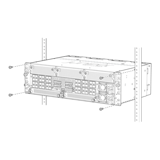
- Page 80 Mount an ACX7348 in a Four-Post Rack | 74 You can install an ACX7348 router into a two-post rack, four-post rack, or a cabinet. Mount an ACX7348 in a Two-Post Rack Be sure that you have the following parts and tools available to install the router: •...
- Page 81 NOTE: We ship the ACX7348 routers with preinstalled two-post mounting brackets. To mount an ACX7348 router on two posts of a rack: 1. Wrap and fasten one end of the ESD wrist strap around your bare wrist, and connect the other end of the strap to the ESD point on the device.
- Page 82 Figure 26: ACX7348 Router Installed in a Two-Post Rack Mount an ACX7348 in a Four-Post Rack Be sure that you have the following parts and tools available to install the router: • An ESD grounding strap—not provided • A Phillips (+) screwdriver—not provided To install the router in a four-post rack: 1.
- Page 83 Figure 27: Remove the Two-Post Mounting Brackets 3. Assemble the bracket assembly. a. Detach the removable telescopic rail. The telescopic rail assembly consists of three parts. See Figure 28 on page Figure 28: Telescopic Rail Assembly Removable telescopic rail bracket Fixed telescopic rail —...
- Page 84 Figure 29: Assemble the Telescopic Rail Bracket Assembly 4. Attach the bracket assembly to the chassis. a. Align the keyholes in the bracket assembly to the aligned holes on the chassis. b. Push the bracket assembly towards the front of the chassis to lock the bracket assembly in place. Figure 30: Attach the Bracket Assembly to the Chassis 5.
- Page 85 Figure 31: Attach the Telescopic Rails to the Rack Rails 6. Extend the middle telescopic rails until it stops. Figure 32: Extend the Middle Telescopic Rails 7. Grasp both sides of the router, lift it, and position the router so that the telescopic rail bracket attached to the chassis slides into the channel of the middle telescopic rails.
- Page 86 Figure 33: Slide the Router into the Rack 8. Press the latch on the side of the telescopic rail bracket to push the chassis further until the front- mounting ears contact the front rack rails. Figure 34: Slide the Router into the Rack 9.
- Page 87 Figure 35: ACX7348 Router Installed in a Four-Post Rack Connect ACX7348 to Power IN THIS SECTION SUMMARY Connect Earth Ground to ACX7348 Learn how to ground the ACX7348 Router and Routers | 79 connect it to AC and DC power.
- Page 88 To meet safety and electromagnetic interference (EMI) requirements and to ensure proper operation, you must ground the router properly before connecting power. You must install the ACX7348 in a restricted-access location and ensure that the chassis is always properly grounded. The ACX7348 has a two-hole protective grounding terminal provided on the chassis...
- Page 89 Figure 37: Connect the Grounding Cable to the ACX7348 Router 5. Secure the grounding cable lug with the screws. 6. Dress the grounding cable and verify that it does not touch or block access to router components, and that it does not drape where people could trip over it.
- Page 90 The PSM in an ACX7348 router is a hot-removable and hot-insertable field-replaceable unit (FRU). You can remove and replace it without powering off the router or disrupting routing functions. To connect AC power to an ACX7348 router: Wrap and fasten one end of the ESD grounding strap around your bare wrist, and connect the other end of the strap to the ESD point on the chassis.
- Page 91 • Install the PSM in the chassis. Ensure that you have the following parts and tools available: • Two DC power source cables. The ACX7348 supports a 6 AWG and 90 °C temperature-rated stranded copper wire. • An electrostatic discharge (ESD) grounding wrist strap (not provided) •...
- Page 92 The DC PSM has two terminals labeled -48V/-60V (negative) and RTN (positive) for connecting the DC power cables labeled positive (+) and negative (-). The terminals are covered by a cover on the terminal block. Using a screwdriver, unscrew (counterclockwise) the nut on top of the terminal block. Figure 39: Removing the Terminal Block Cover Install heat-shrink tubing insulation around the power cables.
- Page 93 Figure 40: How to Install Heat-Shrink Tubing Remove the nuts from the four terminals. See Figure 41 on page Figure 41: Removing the Nuts from the Terminals Secure each power cable lug to the terminal with the nuts. Tighten the nuts on the power supply terminals until snug by using the screwdriver.
- Page 94 Figure 42: Connecting the DC Cable NOTE: To connect the DC source to an ACX7348 router, use a 6 AWG and 90 °C temperature-rated stranded copper wire. a. Secure the positive (+) DC source power cable lug to the RTN (return) terminal.
- Page 95 Antenna | 90 Connect an ACX7348 Router to a Management Console Each ACX7348 router has a console port with an RJ-45 connector. Use the console port to connect the device to a management console or to a console server. To connect the ACX7348 router to a management console: 1.
- Page 96 To connect an ACX7348 router to a network for out-of-band management: 1. Connect one end of the cable to the management port labeled MGMT on the ACX7348 router. 2. Connect the other end of the cable to the management PC (see Figure 45 on page 89).
- Page 97 Figure 45: Connect an ACX7348 Router to a Network for Out-of-Band Management Connect to 1-PPS and 10-MHz Timing Devices Each ACX7348 router has SubMiniature B (SMB) connector ports that support 1 pulse per second (1- PPS) and 10-megahertz (10-MHz) timing devices.
- Page 98 Guidelines. To connect an ACX7348 router to a GNSS antenna: 1. Connect one end of the LMR400 cable to the GNSS connector port (labeled GNSS) on the ACX7348 router. 2. Connect the other end of the LMR400 cable to the GNSS antenna. See...
- Page 99 Figure 46: LMR400 Cable Connections Juniper has tested this topology with the following LMR400 cables: • LMR400 (10 m segment) from TE Connectivity. For more information, see Figure 47 on page • LMR400 (100 m segment) from TE Connectivity. For more information, see Figure 48 on page •...
- Page 100 Figure 48: LMR400 (100 m Segment) Cable Specifications Figure 49: LMR195 (5 m Segment) Cable Specifications Electrical Characteristics of LMR400 Cable Impedance 50 Ω Frequency DC-3GHz Voltage Rating 335 Vrms Dielectric Withstanding Voltage > 1000 V...
- Page 101 You can easily customize the factory-default configuration with just a few commands. Initially, you’ll need to make changes through the console port. After you configure the management port, you can access the ACX7348 using SSH and make additional configuration changes. You can always revert to the factory-default configuration whenever you want.
- Page 102 • Stop Bits—1 • DCD State—Disregard Connect the console port on the ACX7348 to a laptop or a desktop PC using the RJ-45 cable and RJ-45 to DB-9 adapter. The console (CON) port is the RJ-45 port on the Routing Engine.
- Page 103 NOTE: ZTP is enabled on the ACX7348 in the factory-default configuration. You must stop ZTP before you configure any settings. Until you assign a root password and perform an initial commit, you might see ZTP-related messages on the console. You can safely ignore these messages while you configure the root password.
- Page 104 14. Enable Telnet service, if required. [edit] root@re0# set system services telnet NOTE: When Telnet is enabled, you cannot log in to the ACX7348 using root credentials. Root login is allowed only for SSH access. 15. Enable SSH service. [edit]...
- Page 105 16. To allow users to log in to the router as root users through SSH, include the root-login statement. [edit system services ssh] root@re0# root-login (allow) NOTE: By default, users are not allowed to log in to the router as root users through SSH. 17.
- Page 106 C HAPTER Maintaining Components ACX7348 Fan Tray Maintenance | 99 ACX7348 Air Filter Unit Maintenance | 102 ACX7348 Power Supply Module Maintenance | 110 ACX7348 Routing Engine Maintenance | 118 ACX7348 Flexible PIC Concentrator Maintenance | 120...
- Page 107 Before you remove a fan tray: • Ensure that you understand how to prevent ESD damage. • Ensure that you have the following parts and tools available to remove a fan tray from the ACX7348 router: • Electrostatic discharge (ESD) grounding strap...
- Page 108 CAUTION: Do not remove the fan tray unless you have a replacement fan tray available. The fan tray on an ACX7348 router can be accessed from the front or the rear of the chassis. Remove a Fan Tray from the Rear of the Chassis To remove a fan tray from the rear of the chassis: 1.
- Page 109 Before you begin to install a fan tray: • Ensure that you understand how to prevent ESD damage. • Ensure that you have the following parts and tools available to install a fan tray in an ACX7348 router: • Electrostatic discharge (ESD) grounding strap •...
- Page 110 NOTE: The fan tray LED will glow green when a fan tray is inserted. Figure 52: Install a Fan Tray in an ACX7348 Router ACX7348 Air Filter Unit Maintenance IN THIS SECTION SUMMARY Install Air Filter Unit in a Two-Post...
- Page 111 Figure 53: Air Filter Unit Outer filter cover Inner cage — — Air filter Cable management brackets — — NOTE: You must replace the air filter every 6 months. Install Air Filter Unit in a Two-Post Rack To install an air filter unit in a two-post rack: 1.
- Page 112 Figure 54: Attach the Cable Management Brackets to the Chassis 3. Grasp both sides of the router, lift the router, and position it in the rack, aligning the holes of the mounting brackets with the holes in the front post of the rack. Align the bottom hole in both the mounting brackets with a hole in each rack post, making sure that the chassis is level.
- Page 113 Figure 56: Install the Air Filter 6. Tighten the captive screws to secure the air filter unit to the cable management brackets. Install Air Filter Unit in a Four-Post Rack To install an air filter unit in a four-post rack: 1.
- Page 114 Figure 57: Loosen the Thumb Screws 2. Attach the cable management brackets on both sides of the chassis. Figure 58: Attach Cable Management Brackets on the Chassis 3. Push the chassis back (with the cable management brackets installed) and tighten the thumb screws to secure the device to the 4 post rack.
- Page 115 Figure 59: Tighten the Thumb Screws 4. Slide the outer cage into the rails on the cable management brackets until it stops. Figure 60: Attach the Filter Door 5. Tighten the captive screws to secure the air filter unit to the cable management brackets.
- Page 116 Replace the Air Filter IN THIS SECTION Remove the Air Filter | 108 Install the Air Filter | 109 The air filter sits right inside the outer filter cover and the inner cage. The air filter unit is installed into the cable management brackets, and is held tightly by captive screws.
- Page 117 Figure 61: Remove the Air Filter from the Chassis Install the Air Filter To install the air filter: 1. Attach an electrostatic discharge (ESD) grounding strap to your bare wrist, and connect the strap to one of the ESD points on the chassis. 2.
- Page 118 Install an ACX7348 DC Power Supply Module | 115 The power supply modules (PSMs) in an ACX7348 router are hot-removable and hot-insertable field- replaceable units (FRUs). You can remove and replace the PSMs without powering off the router or disrupting routing functions.
- Page 119 Figure 63 on page 111). Figure 63: Remove an AC PSM from the ACX7348 Router 6. Grasp the PSM handle and pull firmly to slide the PSM halfway out of the chassis. 7. Place one hand under the PSM to support it and slide it completely out of the chassis. Take care not to touch power supply components, pins, leads, or solder connections.
- Page 120 4. Attach the power cord to the PSM (see Figure 65 on page 112). Figure 65: Install an AC Power Cord on an ACX7348 Router 5. Attach the power cord to the AC power source, and switch on the dedicated customer-site 2-pole circuit breaker.
- Page 121 6. Observe the status LED on the power supply faceplate. If the PSM is correctly installed and functioning normally, the status LED lights green steadily. Remove an ACX7348 DC Power Supply Module Before you remove a power supply module (PSM), be aware of the following: NOTE: The minimum required number of PSMs must always be present in the router.
- Page 122 Carefully move the power cables out of the way. Press the ejector lever located on the DC PSM, to release it from the chassis. Figure 67: Remove a DC PSM from an ACX7348 Router 10. Pull the PSM straight out of the chassis.
- Page 123 3. Using both hands, slide the DC PSM straight into the slot on the front panel of the chassis until the PSM is fully seated in the slot. Figure 68: Install a DC PSM in an ACX7348 Router 4. Connect to power.
- Page 124 Figure 69: Removing the Terminal Block Cover b. Remove the nuts from the terminals. Figure 70: Removing the Nuts from the Terminals c. Secure each power cable lug to the terminal with the nuts. Tighten the nuts on the power supply terminals until snug by using the screwdriver.
- Page 125 CAUTION: Ensure that each power cable lug seats flush against the surface of the terminal block as you are tightening the nuts. Ensure that each nut is properly threaded into the terminal. Applying installation torque to the nuts when improperly threaded can result in damage to the terminal. CAUTION: You must ensure that power connections maintain the proper polarity.
- Page 126 Install the Routing Engine in the ACX7348 Router | 119 The ACX7348 router is shipped with one or two Routing Engines preinstalled in the chassis, depending on the configuration. You can install the Routing Engines in the two bottom slots on the front of the chassis.
- Page 127 5. Grasp both ejector handles and slide the Routing Engine about halfway out of the chassis. Figure 72: Removing a Routing Engine from the ACX7348 Router 6. Grasp the ejector handle with one hand, and place your other hand under the Routing Engine for support as you slide it completely out of the chassis.
- Page 128 7. To verify that the Routing Engine is functioning normally, check the PWR LED and the STS LED on its faceplate. Both LEDs should light steadily, shortly after the Routing Engine is installed. ACX7348 Flexible PIC Concentrator Maintenance IN THIS SECTION...
- Page 129 Flexible PIC Concentrators (FPCs) on the ACX7348 router are field-replaceable units (FRUs) that can be installed in FPC slots on the front of the chassis. The FPCs are hot-pluggable—you can remove and replace them without powering off the router. Before you replace an FPC from the router chassis: •...
- Page 130 2. Wrap and fasten one end of the ESD grounding strap around your bare wrist, and connect the other end of the strap to an ESD point on the chassis. An ESD point is located on the front of the ACX7348...
- Page 131 2. Wrap and fasten one end of the ESD grounding strap around your bare wrist, and connect the other end of the strap to an ESD point on the chassis. An ESD point is located on the front of the ACX7348...
- Page 132 Figure 77: Installing an ACX7348 FPC...
- Page 133 C HAPTER Troubleshooting Hardware Troubleshooting the ACX7348 Router | 126...
- Page 134 Troubleshooting ACX7348 routers includes ACX7348 Routers | 126 recognizing alarm types and alarm severity classes and resolving the error conditions that trigger alarms. Alarm Types and Severity Classes on ACX7348 Routers IN THIS SECTION Alarm Types | 127 Alarm Severity Classes | 127...
- Page 135 J-Web interface display or CLI display. Alarm Severity Classes Alarms on ACX7348 routers have two severity classes: • Major (steady red)—Indicates a critical situation on the router that has resulted from one of the following conditions. A major alarm condition requires immediate action.
- Page 136 C HAPTER Contacting Customer Support and Returning the Chassis or Components Returning an ACX7348 Chassis or Components | 129...
- Page 137 NOTE: Do not return any component to Juniper Networks, Inc. unless you have first obtained an RMA number. Juniper Networks, Inc. reserves the right to refuse shipments that do not have an RMA number.
- Page 138 Locate the Serial Number ID Label on an ACX7348 Fan Tray | 132 Locate the Serial Number ID Label on an ACX7348 Power Supply Module | 132 Locate the Serial Number ID Label on an ACX7348 Routing Engine | 133...
- Page 139 Locate the Chassis Serial Number ID Label on an ACX7348 Router On the ACX7348 router, the chassis serial number ID label is located on the top corner of the chassis, as shown in Figure 78 on page 131.
- Page 140 Locate the Serial Number ID Label on an ACX7348 Fan Tray The fan tray installed in an ACX7348 router is a field-replaceable unit (FRU). For each FRU, you must remove the FRU from the router chassis to see the FRU serial number ID label.
- Page 141 Locate the Serial Number ID Label on an ACX7348 Routing Engine The Routing and Control Boards (RCBs) installed in an ACX7348 router are field-replaceable units (FRUs). For each FRU, you must remove the FRU from the router chassis to see the FRU serial number ID label.
- Page 142 Locate the Serial Number ID Label on an ACX7348 Flexible PIC Concentrator The Flexible PIC Concentrator (FPC) installed in an ACX7348 router is a field-replaceable unit (FRU). For each FRU, you must remove the FRU from the router chassis to see the FRU serial number ID label.
- Page 143 — Contact Customer Support to Obtain Return Material Authorization If you are returning a device or hardware component to Juniper Networks for repair or replacement, obtain a Return Material Authorization (RMA) number from the Juniper Networks Technical Assistance Center (JTAC).
- Page 144 Guidelines for Packing and Shipping Hardware Components To pack and ship individual components: 1. When you return components, make sure that they are adequately protected with packing materials and packed so that the pieces are prevented from moving around inside the carton. 2.
- Page 145 C HAPTER Safety and Compliance Information Safety Information | 138 Compliance Statements for NEBS | 138 Compliance Statements for EMC Requirements | 138 Compliance Standards for ACX7348 Routers | 140...
- Page 146 Networks products. Follow the guidelines provided in the guide to reduce the likelihood of personal injury, equipment damage, and damage to surrounding areas. Along with the information provided in the Juniper Networks Safety Guide, you must read and understand the ACX7348 specific safety information provided in this hardware guide.
- Page 147 Canada CAN ICES-3 (A)/NMB-3(A) European Community This is a Class A product. In a domestic environment, this product might cause radio interference in which case the user might be required to take adequate measures. Israel Translation from Hebrew—Warning: This product is Class A. In residential environments, the product might cause radio interference, and in such a situation, the user might be required to take adequate measures.
- Page 148 Operation of this equipment in a residential area is likely to cause harmful interference in which case the user will be required to correct the interference at his own expense. Compliance Standards for ACX7348 Routers The ACX7348 routers comply with the following standards: • Safety • UL 60950-1:2007 R10.14 Information Technology Equipment •...
- Page 149 • ICES-003 / ICES-GEN • BS EN 55032 • BS EN 55035 • EN 300 386 V1.6.1 • EN 300 386 V2.2.1 • EN 301 489-1 • EN 301 489-19 • BS EN 300 386 • EN 55032 • CISPR 32 •...
- Page 150 • GR-3108 Class 2 Edition 3 • Radio Frequency • EN 303 413 • ETSI • ETSI Operational EN 300 019 Class 3.2 • ETSI Storage EN 300 019 2.1 Class 1.2 • ETSI Transportation EN 300 019 Class 2.3...
Need help?
Do you have a question about the ACX7348 and is the answer not in the manual?
Questions and answers