Juniper ACX2000 Hardware Manual
Hide thumbs
Also See for ACX2000:
- Hardware manual (172 pages) ,
- Quick start manual (30 pages) ,
- Configuration manual (3270 pages)
Table of Contents
Advertisement
Quick Links
Advertisement
Table of Contents
Troubleshooting

Related Manuals for Juniper ACX2000


Summary of Contents for Juniper ACX2000
- Page 1 ACX2000 and ACX2100 Universal Metro Router Hardware Guide Published 2020-09-07...
- Page 2 END USER LICENSE AGREEMENT The Juniper Networks product that is the subject of this technical documentation consists of (or is intended for use with) Juniper Networks software. Use of such software is subject to the terms and conditions of the End User License Agreement (“EULA”) posted at https://support.juniper.net/support/eula/.
-
Page 3: Table Of Contents
Benefits of the ACX2000 and ACX2100 Routers | 18 ACX2000 Router Description | 18 ACX2100 Router Description | 19 ACX2000 and ACX2100 Routers Hardware and CLI Terminology Mapping | 20 ACX2000 Hardware and CLI Terminology Mapping | 20 ACX2100 Hardware and CLI Terminology Mapping | 22... - Page 4 SFP and SFP+ Port LEDs | 59 Management and Console Port LEDs on the Front Panel | 60 Cooling System and Airflow in an ACX2000 and ACX2100 Router | 60 ACX2000 Power System | 61 ACX2000 and ACX2100 Power Overview | 62...
- Page 5 ACX2000 and ACX2100 Alarm, Management, and Clocking Cable Specifications and Pinouts | 85 Alarm Contact Port Pinouts on the ACX2000 and ACX2100 Router | 85 Management Port Connector Pinout Information for ACX Series Routers | 87 Console or Auxiliary Port Connector Pinout on ACX Series Routers | 88...
- Page 6 Connecting 1-PPS and 10-MHz Timing Devices to the Router | 108 Connecting a T1 or E1 External Clocking Device to the Router | 109 Connecting ACX2000 or ACX2100 Routers to an External Alarm-Reporting Device | 110 Initially Configuring the ACX2000 or ACX2100 Router | 111...
- Page 7 Contacting Customer Support and Returning the Chassis or Components | 131 How to Return a Hardware Component to Juniper Networks, Inc. | 131 Locating the Serial Number on a ACX2000 or ACX2100 Chassis or Component | 132 ACX2000 and ACX2100 Chassis Serial Number Label | 133...
- Page 8 TN Power Warning | 185 Agency Approvals for ACX2000 and ACX2100 Routers | 185 Compliance Statements for NEBS for ACX2000 and ACX2100 Routers | 187 Compliance Statements for EMC Requirements for ACX2000 and ACX2100 Routers | 188 Canada | 188 European Community | 188...
-
Page 9: About The Documentation
Use this guide to install hardware and perform initial software configuration, routine maintenance, and troubleshooting for the ACX2000 and ACX2100 Universal Metro router. After completing the installation and basic configuration procedures covered in this guide, refer to the Junos OS documentation for information about further software configuration. -
Page 10: Merging A Full Example
If the example configuration contains the top level of the hierarchy (or multiple hierarchies), the example is a full example. In this case, use the load merge command. If the example configuration does not start at the top level of the hierarchy, the example is a snippet. In this case, use the load merge relative command. -
Page 11: Merging A Snippet
Merging a Snippet To merge a snippet, follow these steps: 1. From the HTML or PDF version of the manual, copy a configuration snippet into a text file, save the file with a name, and copy the file to a directory on your routing platform. For example, copy the following snippet to a file and name the file ex-script-snippet.conf. - Page 12 Table 1: Notice Icons Icon Meaning Description Informational note Indicates important features or instructions. Caution Indicates a situation that might result in loss of data or hardware damage. Warning Alerts you to the risk of personal injury or death. Laser warning Alerts you to the risk of personal injury from a laser.
- Page 13 xiii Table 2: Text and Syntax Conventions (continued) Convention Description Examples Italic text like this Represents variables (options for Configure the machine’s domain which you substitute a value) in name: commands or configuration [edit] statements. root@# set system domain-name domain-name Text like this Represents names of configuration To configure a stub area, include...
-
Page 14: Documentation Feedback
URL or page number, and software version (if applicable). Requesting Technical Support Technical product support is available through the Juniper Networks Technical Assistance Center (JTAC). If you are a customer with an active Juniper Care or Partner Support Services support contract, or are... -
Page 15: Self-Help Online Tools And Resources
JTAC hours of operation—The JTAC centers have resources available 24 hours a day, 7 days a week, 365 days a year. Self-Help Online Tools and Resources For quick and easy problem resolution, Juniper Networks has designed an online self-service portal called the Customer Support Center (CSC) that provides you with the following features: Find CSC offerings: https://www.juniper.net/customers/support/... -
Page 16: Overview
C HAPTER Overview ACX2000 and ACX2100 System Overview | 17 ACX2000 Chassis Components | 47 Cooling System and Airflow in an ACX2000 and ACX2100 Router | 60 ACX2000 Power System | 61... -
Page 17: Acx2000 And Acx2100 System Overview
ACX2000 Router Description | 18 ACX2100 Router Description | 19 The ACX2000 and ACX2100 Universal Metro Routers are principally designed to provide superior management for rapid provisioning to the access network. The ACX Series routers support rich Gigabit Ethernet and 10-Gigabit Ethernet capabilities for uplink, along with support for legacy interfaces and Gigabit Ethernet interfaces for radio and NodeB connectivity in a compact form factor that is environmentally hardened and passively cooled. -
Page 18: Benefits Of The Acx2000 And Acx2100 Routers
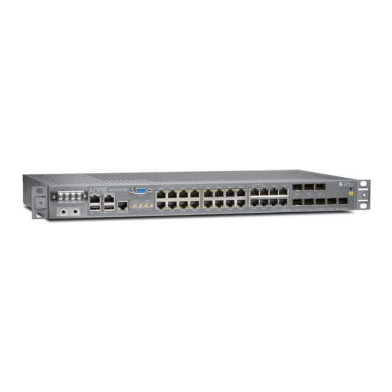
ACX2000 router also supports installation of two Gigabit Ethernet SFP transceivers and two 10-Gigabit Ethernet SFP+ transceivers. The ACX2000 router has one “pseudo” Flexible PIC Concentrator (FPC 0), and four “pseudo” PICs (PIC 0 through 3). Figure 1 on page 19 shows the front view of the ACX2000 router. -
Page 19: Acx2100 Router Description
Figure 1: Front View of the ACX2000 Router 0/1/2 0/1/3 POE Figure 2: Rear View of the ACX2000 Router ACX2100 Router Description The ACX2100 router contains sixteen T1/E1 ports, and four Gigabit Ethernet ports. The ACX2100 router also contains two ports for installing Gigabit Ethernet SFP transceivers and two ports for installing 10-Gigabit Ethernet SFP+ transceivers. -
Page 20: Acx2000 And Acx2100 Routers Hardware And Cli Terminology Mapping
Junos OS command line interface (CLI). Figure 5 on page 22 shows the port locations of the interfaces. Table 3: CLI Equivalents of Terms Used in Documentation for ACX2000 Routers Hardware Item (as Description (as... - Page 21 Table 3: CLI Equivalents of Terms Used in Documentation for ACX2000 Routers (continued) Hardware Item (as Description (as Value (as displayed displayed in the displayed in in the CLI) CLI) the CLI) Item in Documentation Additional Information PIC (n) Abbreviated name of...
-
Page 22: Acx2100 Hardware And Cli Terminology Mapping
Table 3: CLI Equivalents of Terms Used in Documentation for ACX2000 Routers (continued) Hardware Item (as Description (as Value (as displayed displayed in the displayed in in the CLI) CLI) the CLI) Item in Documentation Additional Information – “Cooling System and Airflow in... - Page 23 Overview” on page 17 Xcvr (n) Abbreviated name of n is a value Optical transceivers “Uplink Ports on ACX2000 and the transceiver equivalent to the ACX2100 Routers” on page 50 number of the port in which the transceiver is installed.
-
Page 24: Packet Flow On Acx Series Routers
CLI) CLI) CLI) Item in Documentation Additional Information – “Cooling System and Airflow in an ACX2000 and ACX2100 NOTE: ACX2100 Router” on page 60 routers are fanless models. Figure 6: ACX2100 Interface Port Mapping FPC 1, PIC 2... - Page 25 Forwarding class Rate limiting Qn + packet loss priority WRED Forwarding class and packet loss priority Scheduling and determine rewrite value shaping SEE ALSO ACX2000 and ACX2100 Routers Hardware and CLI Terminology Mapping | 20 Configuring CoS on ACX Series Routers...
-
Page 26: Protocols And Applications Supported By Acx Series Routers
MTU values are not limited to 1500 but can range between 256 to 9216. For more information, see the Knowledge Base (KB) article KB28179 at: https://kb.juniper.net/InfoCenter/index?page=content&id=KB28179. Table 5: Protocols and Applications Supported by ACX Series Routers Protocol or... - Page 27 Table 5: Protocols and Applications Supported by ACX Series Routers (continued) Protocol or Application A C X 1 0 0 0 A C X 1 1 0 0 A C X 2 0 0 0 A C X 2 1 0 0 A C X 2 2 0 0 A C X 4 0 0 0 A C X 5 0 4 8...
- Page 28 Table 5: Protocols and Applications Supported by ACX Series Routers (continued) Protocol or Application A C X 1 0 0 0 A C X 1 1 0 0 A C X 2 0 0 0 A C X 2 1 0 0 A C X 2 2 0 0 A C X 4 0 0 0 A C X 5 0 4 8...
- Page 29 Table 5: Protocols and Applications Supported by ACX Series Routers (continued) Protocol or Application A C X 1 0 0 0 A C X 1 1 0 0 A C X 2 0 0 0 A C X 2 1 0 0 A C X 2 2 0 0 A C X 4 0 0 0 A C X 5 0 4 8...
- Page 30 Table 5: Protocols and Applications Supported by ACX Series Routers (continued) Protocol or Application A C X 1 0 0 0 A C X 1 1 0 0 A C X 2 0 0 0 A C X 2 1 0 0 A C X 2 2 0 0 A C X 4 0 0 0 A C X 5 0 4 8...
- Page 31 Table 5: Protocols and Applications Supported by ACX Series Routers (continued) Protocol or Application A C X 1 0 0 0 A C X 1 1 0 0 A C X 2 0 0 0 A C X 2 1 0 0 A C X 2 2 0 0 A C X 4 0 0 0 A C X 5 0 4 8...
- Page 32 Table 5: Protocols and Applications Supported by ACX Series Routers (continued) Protocol or Application A C X 1 0 0 0 A C X 1 1 0 0 A C X 2 0 0 0 A C X 2 1 0 0 A C X 2 2 0 0 A C X 4 0 0 0 A C X 5 0 4 8...
- Page 33 Table 5: Protocols and Applications Supported by ACX Series Routers (continued) Protocol or Application A C X 1 0 0 0 A C X 1 1 0 0 A C X 2 0 0 0 A C X 2 1 0 0 A C X 2 2 0 0 A C X 4 0 0 0 A C X 5 0 4 8...
- Page 34 Table 5: Protocols and Applications Supported by ACX Series Routers (continued) Protocol or Application A C X 1 0 0 0 A C X 1 1 0 0 A C X 2 0 0 0 A C X 2 1 0 0 A C X 2 2 0 0 A C X 4 0 0 0 A C X 5 0 4 8...
- Page 35 Table 5: Protocols and Applications Supported by ACX Series Routers (continued) Protocol or Application A C X 1 0 0 0 A C X 1 1 0 0 A C X 2 0 0 0 A C X 2 1 0 0 A C X 2 2 0 0 A C X 4 0 0 0 A C X 5 0 4 8...
- Page 36 Table 5: Protocols and Applications Supported by ACX Series Routers (continued) Protocol or Application A C X 1 0 0 0 A C X 1 1 0 0 A C X 2 0 0 0 A C X 2 1 0 0 A C X 2 2 0 0 A C X 4 0 0 0 A C X 5 0 4 8...
- Page 37 Table 5: Protocols and Applications Supported by ACX Series Routers (continued) Protocol or Application A C X 1 0 0 0 A C X 1 1 0 0 A C X 2 0 0 0 A C X 2 1 0 0 A C X 2 2 0 0 A C X 4 0 0 0 A C X 5 0 4 8...
- Page 38 Table 5: Protocols and Applications Supported by ACX Series Routers (continued) Protocol or Application A C X 1 0 0 0 A C X 1 1 0 0 A C X 2 0 0 0 A C X 2 1 0 0 A C X 2 2 0 0 A C X 4 0 0 0 A C X 5 0 4 8...
- Page 39 Table 5: Protocols and Applications Supported by ACX Series Routers (continued) Protocol or Application A C X 1 0 0 0 A C X 1 1 0 0 A C X 2 0 0 0 A C X 2 1 0 0 A C X 2 2 0 0 A C X 4 0 0 0 A C X 5 0 4 8...
- Page 40 Table 5: Protocols and Applications Supported by ACX Series Routers (continued) Protocol or Application A C X 1 0 0 0 A C X 1 1 0 0 A C X 2 0 0 0 A C X 2 1 0 0 A C X 2 2 0 0 A C X 4 0 0 0 A C X 5 0 4 8...
- Page 41 Table 5: Protocols and Applications Supported by ACX Series Routers (continued) Protocol or Application A C X 1 0 0 0 A C X 1 1 0 0 A C X 2 0 0 0 A C X 2 1 0 0 A C X 2 2 0 0 A C X 4 0 0 0 A C X 5 0 4 8...
- Page 42 Table 5: Protocols and Applications Supported by ACX Series Routers (continued) Protocol or Application A C X 1 0 0 0 A C X 1 1 0 0 A C X 2 0 0 0 A C X 2 1 0 0 A C X 2 2 0 0 A C X 4 0 0 0 A C X 5 0 4 8...
- Page 43 Table 5: Protocols and Applications Supported by ACX Series Routers (continued) Protocol or Application A C X 1 0 0 0 A C X 1 1 0 0 A C X 2 0 0 0 A C X 2 1 0 0 A C X 2 2 0 0 A C X 4 0 0 0 A C X 5 0 4 8...
- Page 44 Table 5: Protocols and Applications Supported by ACX Series Routers (continued) Protocol or Application A C X 1 0 0 0 A C X 1 1 0 0 A C X 2 0 0 0 A C X 2 1 0 0 A C X 2 2 0 0 A C X 4 0 0 0 A C X 5 0 4 8...
- Page 45 Table 5: Protocols and Applications Supported by ACX Series Routers (continued) Protocol or Application A C X 1 0 0 0 A C X 1 1 0 0 A C X 2 0 0 0 A C X 2 1 0 0 A C X 2 2 0 0 A C X 4 0 0 0 A C X 5 0 4 8...
- Page 46 12. 3 X54 18.2R1 –D15 -D10 –D20 –D20 –D20 (Indoor) 12. 3 X54 –D25 ( O utdoor) Juniper Networks 12.2 12.2R2 12.2 12.2R2 12. 3 X54 12. 3 x51 15. 1 X54 15. 1 X54 12. 3 X54 18.2R1 enterprise-specific MIBs –D15...
-
Page 47: Acx2000 Chassis Components
Clocking Ports on the ACX2000 and the ACX2100 Router | 56 LEDs on ACX2000 and ACX2100 Routers | 57 Front Panel of an ACX2000 Router The front panel of an ACX2000 router consists of the following components (see Figure 9 on page 48):... -
Page 48: Front Panel Of An Acx2100 Router
— — SEE ALSO ACX2000 and ACX2100 Universal Metro Router Overview | 17 LEDs on ACX2000 and ACX2100 Routers | 57 Front Panel of an ACX2100 Router The front panel of an ACX2100 router consists of the following components (see... - Page 49 External clocking ports supporting 1PPS and 10MHz input and output Network ports and corresponding status LEDs: Sixteen T1/E1 ports labeled 0/0/0 through 0/0/15 Four Gigabit Ethernet (GE) ports labeled 1/0/0 through 1/0/3 Combination (COMBO) ports labeled 1/1/0 through 1/1/3, either: Four Gigabit Ethernet RJ-45 ports Four Gigabit Ethernet SFP ports Two Gigabit Ethernet (GE) ports labeled 1/2/0 through 1/2/1 that accept SFP transceivers...
-
Page 50: Uplink Ports On Acx2000 And Acx2100 Routers
T1/E1 Ports | 51 Gigabit Ethernet RJ-45 Ports | 52 PoE Ports | 52 Gigabit Ethernet SFP Ports | 53 10-Gigabit Ethernet SFP+ Ports | 54 Unless otherwise specified, the information about uplink ports applies to both ACX2000 and ACX2100 routers. -
Page 51: T1/E1 Ports
TIP: You can find information about the pluggable transceivers supported on your Juniper Networks device by using the Hardware Compatibility Tool. In addition to transceiver and connector type, the optical and cable characteristics—where applicable—are documented for each transceiver. The Hardware Compatibility Tool allows you to search by product, displaying all the transceivers supported on that device, or category, displaying all the transceivers by interface speed or type. -
Page 52: Gigabit Ethernet Rj-45 Ports
T1 framing (default): ct1-0/0/0 through ct1-0/0/15 E1 framing: ce1-0/0/0 through ce1-0/0/15 Gigabit Ethernet RJ-45 Ports The front panel of the ACX2000 router has six Gigabit Ethernet RJ-45 ports, and the ACX2100 router has eight Gigabit Ethernet RJ-45 ports. Table 7 on page 52 describes the ports in more detail. -
Page 53: Gigabit Ethernet Sfp Ports
(SFP) transceivers. NOTE: On the ACX2000 router, you can use Gigabit Ethernet transceivers in the GE ports, or you can use 10-Gigabit Ethernet transceivers in the XE ports. Use one set of ports at a time. On the ACX2100 router, you can use both sets at the same time. -
Page 54: 10-Gigabit Ethernet Sfp+ Ports
The external alarm contact has 15 pins that accept a single core wire from external alarm devices. A DE15 alarm cable is required to connect the ACX2000 and ACX2100 router to external alarm devices. Use the gauge wire appropriate for the external device that you are connecting. - Page 55 reference [REF] or negative potential terminal for Contact 1 of the corresponding alarm and provides a current path for external alarm devices. Table 11 on page 55 describes the functions of the alarm contacts. Table 11: Alarm Relay Contact Functions Contact Name Contact Name Function...
-
Page 56: Clocking Ports On The Acx2000 And The Acx2100 Router
Figure 13: Sample Input Alarm-Reporting Device SEE ALSO Alarm Contact Port Pinouts on the ACX2000 and ACX2100 Router | 85 Clocking Ports on the ACX2000 and the ACX2100 Router The clocking ports acquire the clock source and synchronize communication over time-division multiplexing (TDM) interfaces in the router. -
Page 57: Leds On Acx2000 And Acx2100 Routers
SFP and SFP+ Port LEDs | 59 Management and Console Port LEDs on the Front Panel | 60 Unless otherwise specified, the information about LEDs applies to both ACX2000 and ACX2100 routers. System LED on the Front Panel One bicolor LED labeled SYS indicates the status of the router. -
Page 58: T1/E1 Port Leds
(remote alarms) Ethernet Port LEDs The front panel of the ACX2000 router has six Gigabit Ethernet RJ-45 ports, and the ACX2100 router has eight Gigabit Ethernet RJ-45 ports, each with one pair of port LEDs. Table 14 on page 59 describes the LEDs in more detail. -
Page 59: Poe Port Leds
– The port is not receiving data. PoE Port LEDs The front panel of the ACX2000 router has two PoE Gigabit Ethernet ports, each with one pair of port LEDs. Table 15 on page 59 describes the LEDs in more detail. -
Page 60: Management And Console Port Leds On The Front Panel
Troubleshooting Resources for ACX2000 and ACX2100 Routers | 126 Cooling System and Airflow in an ACX2000 and ACX2100 Router The ACX2000 and ACX2100 routers do not contain fans and are passively cooled by the heatsinks (see Figure 14 on page 61). -
Page 61: Acx2000 Power System
Figure 14: Cooling System and Airflow in an ACX2000 and ACX2100 Router Rear Front RELATED DOCUMENTATION Site Preparation Checklist for ACX2000 and ACX2100 Routers | 68 Rack Requirements for ACX2000 and ACX2100 Routers | 78 Cabinet Requirements for ACX2000 and ACX2100 Routers | 76... -
Page 62: Acx2000 And Acx2100 Power Overview
ACX2000 and ACX2100 Power Overview Both ACX2000 and ACX2100 routers are available as DC-powered models. The ACX2100 is also available as an AC-powered model. The power supply in the router is built along the front panel of the chassis, with the DC power terminals or AC inlets on the front to connect power to the router. -
Page 63: Acx2100 Ac Power Cord Specifications
NOTE: We recommend that you use a dedicated customer site circuit breaker rated for 2 A (100 VAC) or 1 A (240 VAC), or as required by local code. Doing so enables you to operate the router in any configuration without upgrading the power infrastructure. SEE ALSO Connecting AC Power Cords to the ACX2100 Router | 104 ACX2100 AC Power Cord Specifications... - Page 64 Table 20: AC Power Cord Specifications (continued) Country Model Number Electrical Specification Plug Type Design Standard Korea CBL-GP-C15-KR 250 VAC, 10 A, 50 Hz VIIG CEE (7) VII Switzerland CBL-GP-C15-SZ 250 VAC, 10 A, 50 Hz SEV 1011 / 6534-2 North America CBL-GP-C15-US 125 VAC, 13 A, 60 Hz...
-
Page 65: Acx2000 And Acx2100 Dc Power Specifications
ACX2000 and ACX2100 DC Power Specifications The power supplies in DC-powered ACX2000 and ACX2100 routers are built in along the front left panel of the chassis with DC power terminals to connect power to the router. The power supplies are labeled PS0 and PS1. - Page 66 SEE ALSO ACX2000 and ACX2100 DC Power Electrical Safety Guidelines | 172 DC Power Copper Conductors Warning | 173 DC Power Disconnection Warning | 174...
-
Page 67: Site Planning, Preparation, And Specifications
C HAPTER Site Planning, Preparation, and Specifications Site Preparation Checklist for ACX2000 and ACX2100 Routers | 68 ACX2000 and ACX2100 Site Guidelines and Requirements | 69 ACX2000 and ACX2100 Network Cable and Transceiver Planning | 80 ACX2000 and ACX2100 Alarm, Management, and Clocking Cable Specifications and... -
Page 68: Site Preparation Checklist For Acx2000 And Acx2100 Routers
Site Preparation Checklist for ACX2000 and ACX2100 Routers The checklist in Table 22 on page 68 summarizes the tasks you need to perform when preparing a site for router installation. Table 22: Site Preparation Checklist Item or Task For More Information... -
Page 69: Acx2000 And Acx2100 Site Guidelines And Requirements
ACX2000 and ACX2100 Site Guidelines and Requirements IN THIS SECTION General Site Guidelines | 70 Site Electrical Wiring Guidelines | 70 Clearance Requirements for Airflow and Hardware Maintenance on ACX2000 and ACX2100 Routers | 71 Chassis Physical Specifications for ACX2000 and ACX2100 Routers | 72... -
Page 70: General Site Guidelines
ACX2000 and ACX2100 Router Environmental Specifications | 73 ACX2000 and ACX2100 Chassis Grounding Cable and Lug Specifications | 74 Cabinet Requirements for ACX2000 and ACX2100 Routers | 76 Rack Requirements for ACX2000 and ACX2100 Routers | 78 General Site Guidelines Efficient device operation requires proper site planning and maintenance and proper layout of the equipment, rack or cabinet (if used), and wiring closet. -
Page 71: Clearance Requirements For Airflow And Hardware Maintenance On Acx2000 And Acx2100 Routers
Electrical hazards as a result of power surges conducted over the lines into the equipment Clearance Requirements for Airflow and Hardware Maintenance on ACX2000 and ACX2100 Routers When planning the installation site, allow sufficient clearance around the rack (see Figure 15 on page 72): For service personnel to remove and install hardware components, allow at least 2.16 in. -
Page 72: Chassis Physical Specifications For Acx2000 And Acx2100 Routers
Installing and Connecting an ACX2000 or ACX2100 Router Overview | 93 Chassis Physical Specifications for ACX2000 and ACX2100 Routers The ACX2000 router is a rigid sheet-metal structure that houses the hardware components. Table 24 on page 72 summarizes the physical specifications of the ACX2000 router. -
Page 73: Acx2000 And Acx2100 Router Environmental Specifications
ACX2000 and ACX2100 Router Environmental Specifications The router must be installed in a rack or cabinet housed in a dry, clean, well-ventilated, and temperature-controlled environment. Ensure that these environmental guidelines are followed: The site must be as dust-free as possible, because dust can clog air intake vents and filters, reducing the efficiency of the router cooling system. -
Page 74: Acx2000 And Acx2100 Chassis Grounding Cable And Lug Specifications
Install the router only in restricted areas, such as dedicated equipment rooms and equipment closets, in accordance with Articles 110-16, 110-17, and 110-18 of the National Electrical Code, ANSI/NFPA 70. ACX2000 and ACX2100 Chassis Grounding Cable and Lug Specifications IN THIS SECTION Grounding Points Specifications | 74... -
Page 75: Grounding Cable Lug Specifications
Two threaded holes are provided on the front of the router chassis for connecting the router to earth ground. The grounding points fit 0.5-inch-long SAE 10-32 screws (American). The grounding points are spaced at 0.625-in. (15.86-mm) centers. Figure 16: Grounding Points on the ACX2000 and ACX2100 Router T1/E1 ACX2000... -
Page 76: Grounding Cable Specifications
), minimum 90°C wire, or as required by the local code. SEE ALSO Connecting the ACX2000 or ACX2100 Router to Earth Ground | 100 Prevention of Electrostatic Discharge Damage | 168 Cabinet Requirements for ACX2000 and ACX2100 Routers You can mount the router in a cabinet that contains a 19-in. (48.3 cm) rack. - Page 77 Clearance requirements Cabinet airflow requirements Table 26 on page 77 provides the cabinet requirements and specifications for the router. Table 26: Cabinet Requirements and Specifications for the ACX2000 and ACX2100 Router Cabinet Requirement Guidelines Cabinet size You can mount the router in a cabinet that contains a 19-in.
-
Page 78: Rack Requirements For Acx2000 And Acx2100 Routers
Table 26: Cabinet Requirements and Specifications for the ACX2000 and ACX2100 Router (continued) Cabinet Requirement Guidelines Cabinet airflow requirements When you mount the router in a cabinet, ensure that ventilation through the cabinet is sufficient to prevent overheating. Ensure an adequate cool air supply to dissipate the thermal output of the router or routers. - Page 79 Rack size and strength Rack connection to the building structure Table 27 on page 79 provides the rack requirements and specifications for the router. Table 27: Rack Requirements and Specifications for the Router Rack Requirement Guidelines Rack type Use a two-post rack or a four-post rack. You can mount the router on any two-post or four-post rack that provides bracket holes or hole patterns spaced at 1 U (1.75 in., or 4.45 cm) increments and that meets the size and strength requirements to support the weight.
-
Page 80: Acx2000 And Acx2100 Network Cable And Transceiver Planning
Fiber-Optic Cable Signal Loss, Attenuation, and Dispersion | 83 Determining Transceiver Support and Specifications You can find information about the pluggable transceivers supported on your Juniper Networks device by using the Hardware Compatibility Tool. In addition to transceiver and connector type, the optical and cable characteristics—where applicable—are documented for each transceiver. -
Page 81: Calculating Power Budget And Power Margin For Fiber-Optic Cables
You can use the Hardware Compatibility Tool to find information about the pluggable transceivers supported on your Juniper Networks device. To calculate the power budget and power margin, perform the following tasks: How to Calculate Power Budget for Fiber-Optic Cable | 81... -
Page 82: How To Calculate Power Margin For Fiber-Optic Cable
How to Calculate Power Margin for Fiber-Optic Cable After calculating a link's power budget, you can calculate the power margin (P ), which represents the amount of power available after subtracting attenuation or link loss (LL) from the power budget (P ). -
Page 83: Fiber-Optic Cable Signal Loss, Attenuation, And Dispersion
= 7 dB The following sample calculation for an 8-km-long single-mode link with a power budget (P ) of 13 dB uses the estimated values from Table 28 on page 82 to calculate link loss (LL) as the sum of fiber attenuation (8 km @ 0.5 dB/km, or 4 dB) and loss for seven connectors (0.5 dB per connector, or 3.5 dB). -
Page 84: Attenuation And Dispersion In Fiber-Optic Cable
Exceeding the maximum transmission distances can result in significant signal loss, which causes unreliable transmission. Attenuation and Dispersion in Fiber-Optic Cable Correct functioning of an optical data link depends on modulated light reaching the receiver with enough power to be demodulated correctly. Attenuation is the reduction in power of the light signal as it is transmitted. -
Page 85: Acx2000 And Acx2100 Alarm, Management, And Clocking Cable Specifications And Pinouts
Clocking Cable Specifications and Pinouts IN THIS SECTION Alarm Contact Port Pinouts on the ACX2000 and ACX2100 Router | 85 Management Port Connector Pinout Information for ACX Series Routers | 87 Console or Auxiliary Port Connector Pinout on ACX Series Routers | 88... - Page 86 Table 29: Alarm Contact Connector Pinouts (continued) Number Signal Definition Direction CLI Port Mapping Function ALARM_IN2_NO/NC Input Input Alarm Port 2 External alarm input 2 (if voltage on this pin is between 24V to 72V with reference to Pin 8, alarm input 2 is in closed condition) ALARM_IN3_NO/NC Input...
-
Page 87: Management Port Connector Pinout Information For Acx Series Routers
Pin 9 in closed condition) SEE ALSO ACX2000 and ACX2100 Universal Metro Router Overview | 17 Front Panel of an ACX2000 Router | 47 LEDs on ACX2000 and ACX2100 Routers | 57 Management Port Connector Pinout Information for ACX Series Routers The management port—... -
Page 88: Console Or Auxiliary Port Connector Pinout On Acx Series Routers
Table 30: Management Port Connector Pinout Information (continued) Description Direction TRD[2]+ In/Out TRD[3]- In/Out TRD[3]+ In/Out Console or Auxiliary Port Connector Pinout on ACX Series Routers The port labeled CONSOLE/AUX on the front panel is an asynchronous serial interface that accept an RJ-45 connector. -
Page 89: Usb Port Specifications For An Acx Series Router
Clocking Ports Specifications on the ACX2000 and the ACX2100 Router IN THIS SECTION External Clocking Port Connector Specifications | 90 External Clocking Input Port Specifications | 90 Two sets of clocking ports allow you to connect the ACX2000 and ACX2100 router to external clocking devices. -
Page 90: External Clocking Port Connector Specifications
Description Direction EXT_CLKA_RRING_LINE Input EXT_CLKA_RTIP_LINE Input Reserved – EXT_CLKA_TRING_LINE Output EXT_CLKA_TTIP_LINE Output Reserved – Reserved – Reserved – SEE ALSO Clocking Ports on the ACX2000 and the ACX2100 Router | 56 ACX2000 and ACX2100 Universal Metro Router Overview | 17... - Page 91 Front Panel of an ACX2000 Router | 47 LEDs on ACX2000 and ACX2100 Routers | 57...
-
Page 92: Initial Installation And Configuration
C HAPTER Initial Installation and Configuration Installing and Connecting an ACX2000 or ACX2100 Router Overview | 93 Unpacking and Mounting the ACX2000 and ACX2100 Routers | 94 Connecting the ACX2000 and ACX2100 Routers to Power | 99 Connecting the ACX2000 and ACX2100 to External Devices | 105... -
Page 93: Installing And Connecting An Acx2000 Or Acx2100 Router Overview
6. Connect the router to external devices. See: Connecting ACX2000 or ACX2100 Routers to Management Devices on page 106 Connecting ACX2000 or ACX2100 Routers to an External Alarm-Reporting Device on page 110 Connecting ACX2000 or ACX2100 Routers to External Clocking Devices on page 108 7. -
Page 94: Unpacking And Mounting The Acx2000 And Acx2100 Routers
Installing the ACX2000 or ACX2100 Router in the Rack | 97 Unpacking an ACX2000 or ACX2100 Router The ACX2000 and ACX2100 routers are shipped in a cardboard carton, secured with foam packing material. The carton also contains an accessory box. -
Page 95: Parts Inventory (Packing List) For An Acx2000 And Acx2100 Router
Site Preparation Checklist for ACX2000 and ACX2100 Routers | 68 Parts Inventory (Packing List) for an ACX2000 and ACX2100 Router The ACX2000 and ACX2100 routers are shipped in a cardboard carton, secured with foam packing material. The carton also contains an accessory box. -
Page 96: Installing The Acx2000 Or Acx2100 Mounting Brackets
Table 33: Parts List for an ACX2000 and ACX2100 Router (continued) Component Quantity Quick Start installation instructions Juniper Networks Product Warranty End User License Agreement NOTE: You must provide additional mounting screws if needed that are appropriate for your rack or cabinet to mount the chassis on a rack or a cabinet. -
Page 97: Installing The Acx2000 Or Acx2100 Router In The Rack
Figure 18: Installing the Mounting Brackets to the Front of the ACX2000 or ACX2100 Router Figure 19: Installing the Mounting Brackets to the Rear of the ACX2000 or ACX2100 Router Installing the ACX2000 or ACX2100 Router in the Rack NOTE: The router can be installed horizontally in a rack or cabinet. - Page 98 To install the router in the rack (see Figure 20 on page 99): CAUTION: Before front mounting the router in a rack, have a qualified technician verify that the rack is strong enough to support the router's weight (about 7 lb (3.2 kg)) and is adequately supported at the installation site.
-
Page 99: Connecting The Acx2000 And Acx2100 Routers To Power
Connecting the ACX2000 and ACX2100 Routers to Power IN THIS SECTION Connecting the ACX2000 or ACX2100 Router to Earth Ground | 100 Connecting DC Power Cables to the ACX2000 or ACX2100 Router | 102 Connecting AC Power Cords to the ACX2100 Router | 104... -
Page 100: Connecting The Acx2000 Or Acx2100 Router To Earth Ground
Connecting the ACX2000 or ACX2100 Router to Earth Ground To ground the router, you need the following tools: Phillips (+) screwdriver, number 2 ESD grounding wrist strap Two SAE 10-32 screws and flat washers (not provided) Grounding lug, Panduit LCD6-14BH-L or equivalent (not provided) Grounding cable, minimum 14 AWG (2 mm ) 90°... - Page 101 — — SEE ALSO Installing and Connecting an ACX2000 or ACX2100 Router Overview | 93 ACX2000 and ACX2100 Power Overview | 62 ACX2000 and ACX2100 Chassis Grounding Cable and Lug Specifications | 74 Prevention of Electrostatic Discharge Damage | 168...
-
Page 102: Connecting Dc Power Cables To The Acx2000 Or Acx2100 Router
Connecting DC Power Cables to the ACX2000 or ACX2100 Router To connect power to the router, you need the following tools: Phillips (+) screwdriver, number 2 ESD grounding wrist strap M3 screws and flat washers DC power source cables, minimum 14 AWG or as required by local code (not provided) Ring lugs, Molex 190700067 or equivalent (not provided) The DC power supply has four terminals on the front panel, covered by a clear plastic cover. - Page 103 4. Remove the screws and flat washers from the terminals. 5. Secure each power cable lug to the terminal with the flat washers and screw (see Figure 22 on page 104). Apply between 8 lb-in. (0.9 Nm) and 9 lb-in. (1.02 Nm) of torque to each screw. Do not overtighten the screw.
-
Page 104: Connecting Ac Power Cords To The Acx2100 Router
Figure 22: Connecting DC Power to the Router SEE ALSO ACX2000 and ACX2100 Power Overview | 62 Installing and Connecting an ACX2000 or ACX2100 Router Overview | 93 ACX2000 and ACX2100 DC Power Specifications | 65 Connecting AC Power Cords to the ACX2100 Router... -
Page 105: Connecting The Acx2000 And Acx2100 To External Devices
Connecting the ACX2000 and ACX2100 to External Devices IN THIS SECTION Connecting ACX2000 or ACX2100 Routers to Management Devices | 106 Connecting ACX2000 or ACX2100 Routers to External Clocking Devices | 108 Connecting ACX2000 or ACX2100 Routers to an External Alarm-Reporting Device | 110... -
Page 106: Connecting Acx2000 Or Acx2100 Routers To Management Devices
Connecting ACX2000 or ACX2100 Routers to Management Devices IN THIS SECTION Connecting the Router to a Network for Out-of-Band Management | 106 Connecting the Router to a Management Console or Auxiliary Device | 107 To connect external devices and cables to the router, you need the following tools:... -
Page 107: Connecting The Router To A Management Console Or Auxiliary Device
Connecting the Router to a Management Console or Auxiliary Device You can connect a console, laptop, modem, or other auxiliary device by connecting a serial cable to the port on the front panel labeled CONSOLE/AUX. This port accepts a serial cable with an RJ-45 connector, which is provided with the router. -
Page 108: Connecting Acx2000 Or Acx2100 Routers To External Clocking Devices
Connecting 1-PPS and 10-MHz Timing Devices to the Router | 108 Connecting a T1 or E1 External Clocking Device to the Router | 109 The ACX2000 and ACX2100 routers support external clock synchronization for Synchronous Ethernet, T1 or E1 line timing sources, and external inputs. -
Page 109: Connecting A T1 Or E1 External Clocking Device To The Router
4. Verify that the LEDs for the external clock input is lit steadily green. 5. Configure the port. See: Initially Configuring the ACX2000 or ACX2100 Router on page 111 Configuring External Clock Synchronization for ACX Series Routers 6. Issue the show chassis synchronization command to check the status of the port. -
Page 110: Connecting Acx2000 Or Acx2100 Routers To An External Alarm-Reporting Device
Selected since : 2012-10-29 18:29:29 EDT SEE ALSO Clocking Ports Specifications on the ACX2000 and the ACX2100 Router | 89 Connecting ACX2000 or ACX2100 Routers to an External Alarm-Reporting Device To connect the router to external alarm-reporting devices, attach wires to the ALARM relay contacts on the front panel of the router. -
Page 111: Initially Configuring The Acx2000 Or Acx2100 Router
Initially Configuring the ACX2000 or ACX2100 Router The ACX2000 and ACX2100 routers ship with Junos OS preinstalled and ready to be configured when the router is powered on. One 4-GB internal NAND Flash memory device is divided into two partitions (da0s1 and da0s2). - Page 112 This procedure connects the router to the network but does not enable it to forward traffic. For complete information about enabling the router to forward traffic, including examples, see the Junos OS configuration guides. To configure the software: 1. Verify that the router is powered on. 2.
- Page 113 [edit] root@# set system domain-name domain-name 9. Configure the IP address and prefix length for the router’s Ethernet interface. [edit] root@# set interfaces fxp0 unit 0 family inet address address/prefix-length 10. Configure the IP address of a backup router, which is used only while the routing protocol is not running. [edit] root@# set system backup-router address 11.
- Page 114 root@# set system root-authentication ssh-rsa public-key 13. (Optional) Configure the static routes to remote subnets with access to the management port. Access to the management port is limited to the local subnet. To access the management port from a remote subnet, you need to add a static route to that subnet within the routing table.
- Page 115 18. When you have finished configuring the router, exit configuration mode. [edit] root@host# exit root@host> RELATED DOCUMENTATION ACX2000 and ACX2100 Routers Hardware and CLI Terminology Mapping | 20 Protocols and Applications Supported by ACX Series Routers | 26...
-
Page 116: Maintaining Components
C HAPTER Maintaining Components Maintaining ACX2000 and ACX2100 Components | 117... -
Page 117: Maintaining Acx2000 And Acx2100 Components
IN THIS SECTION Routine Maintenance Procedures for the ACX2000 and ACX2100 Router | 117 Maintaining Cables That Connect to ACX2000 or ACX2100 Network Ports | 117 Maintaining the ACX2000 and ACX2100 Uplink Ports | 118 Removing a Transceiver from the ACX2000 or ACX2100 | 119... -
Page 118: Maintaining The Acx2000 And Acx2100 Uplink Ports
On a regular basis: Check the port LEDs. The meaning of the LED states differs for various uplink ports. For more information, “LEDs on ACX2000 and ACX2100 Routers” on page 57. If the router detects a port failure, the router generates an alarm message to be sent to the Routing Engine. -
Page 119: Removing A Transceiver From The Acx2000 Or Acx2100
Online 2x 10GE(LAN) SFP+ SEE ALSO ACX2000 and ACX2100 Routers Hardware and CLI Terminology Mapping | 20 Removing a Transceiver from the ACX2000 or ACX2100 Removing a transceiver does not interrupt router functioning, but the removed transceiver no longer receives or transmits data. - Page 120 WARNING: Do not look directly into a fiber-optic transceiver or into the ends of fiber-optic cables. Fiber-optic transceivers and fiber-optic cables connected to a transceiver emit laser light that can damage your eyes. 4. Remove the cable connector from the transceiver. 5.
-
Page 121: Installing A Transceiver In The Acx2000 Or Acx2100
SEE ALSO Front Panel of an ACX2000 Router | 47 Front Panel of an ACX2100 Router | 48 Uplink Ports on ACX2000 and ACX2100 Routers | 50 Installing a Transceiver in the ACX2000 or ACX2100 To install a transceiver: 1. Wrap and fasten one end of the ESD grounding strap around your bare wrist, and connect the other end of the strap to an ESD point. -
Page 122: Replacing An Acx2000 Or Acx2100 Management Ethernet Cable
Uplink Ports on ACX2000 and ACX2100 Routers | 50 Replacing an ACX2000 or ACX2100 Management Ethernet Cable Removing an ACX2000 or ACX2100 Management Ethernet Cable | 122 Installing an ACX2000 and ACX2100 Management Ethernet Cable | 123 Removing an ACX2000 or ACX2100 Management Ethernet Cable To remove a serial cable connected to a management device: 1. -
Page 123: Installing An Acx2000 And Acx2100 Management Ethernet Cable
Management Port Connector Pinout Information for ACX Series Routers | 87 Replacing an ACX2000 or ACX2100 Console or Auxiliary Cable Removing an ACX2000 or ACX2100 Console or Auxiliary Cable | 123 Installing an ACX2000 or ACX2100 Console or Auxiliary Cable | 124... -
Page 124: Installing An Acx2000 Or Acx2100 Console Or Auxiliary Cable
SEE ALSO Console or Auxiliary Port Connector Pinout on ACX Series Routers | 88 Installing an ACX2000 or ACX2100 Console or Auxiliary Cable The CONSOLE/AUX port on the front panel of the router accepts an RS-232 (EIA-232) serial cable with RJ-45 connectors. -
Page 125: Troubleshooting Hardware
C HAPTER Troubleshooting Hardware Troubleshooting ACX2000 and ACX2100 | 126... -
Page 126: Troubleshooting Acx2000 And Acx2100
Troubleshooting ACX2000 and ACX2100 IN THIS SECTION Troubleshooting Resources for ACX2000 and ACX2100 Routers | 126 Monitoring System Log Messages | 127 Alarm Types and Severity Classes on ACX Series Routers | 127 Verifying Active Alarms | 128 Troubleshooting Resources for ACX2000 and ACX2100 Routers... -
Page 127: Monitoring System Log Messages
The ports are labeled MGMT and CONSOLE/AUX. Link LEDs—Each network port has one pair of port LEDs that indicate the status of the ports. For more information on front panel LEDs, see “LEDs on ACX2000 and ACX2100 Routers” on page Monitoring System Log Messages Purpose Use the monitoring functionality to view system log messages for ACX Series routers. -
Page 128: Alarm Types
Alarm Types The router supports these alarms: Chassis alarms indicate a failure on the router or one of its components. Chassis alarms are preset and cannot be modified. System alarms indicate a missing rescue configuration. System alarms are preset and cannot be modified, although you can configure them to appear automatically in the J-Web interface display or CLI display. - Page 129 1 alarms currently active Alarm time Class Description 2012-04-08 14:13:37 PDT Minor Host 0 Boot from alternate media When the router is functioning normally with no active alarms, the CLI displays the output as shown: user@host> show chassis alarms No alarms currently active Meaning Table 35 on page 129 lists the alarm output fields.
-
Page 130: Contacting Customer Support And Returning The Chassis Or Components | 131
C HAPTER Contacting Customer Support and Returning the Chassis or Components Contacting Customer Support and Returning the Chassis or Components | 131... -
Page 131: Contacting Customer Support And Returning The Chassis Or Components
Do not return any component to Juniper Networks, Inc. unless you have first obtained an RMA number. Juniper Networks, Inc. reserves the right to refuse shipments that do not have an RMA. Refused shipments are returned to the customer by collect freight. -
Page 132: Locating The Serial Number On A Acx2000 Or Acx2100 Chassis Or Component
Locating the Serial Number on a ACX2000 or ACX2100 Chassis or Component Before contacting Juniper Networks, Inc. to request a Return Materials Authorization (RMA), you must find the serial number on the router or component. To display all of the router components and their serial numbers, enter the following command-line interface (CLI) command: user@host>... -
Page 133: Acx2000 And Acx2100 Chassis Serial Number Label
The chassis serial number is located on the rear of the chassis (see Figure 32 on page 133). Figure 32: ACX2000 and ACX2100 Chassis Serial Number Label SN: HS0211483603 Serial number ID label Guidelines for Packing Hardware Components for Shipment... -
Page 134: Packing The Acx Series Router For Shipment
To pack the router for shipment: 1. Retrieve the shipping box and packing materials in which the router was originally shipped. If you do not have these materials, contact your Juniper Networks representative about approved packaging materials. 2. On the console or other management device connected to the Routing Engine, enter CLI operational mode and issue the following command to shut down the router software. -
Page 135: Safety And Compliance Information
C HAPTER Safety and Compliance Information General Safety Guidelines and Warnings | 137 Definitions of Safety Warning Levels | 138 Qualified Personnel Warning | 141 Warning Statement for Norway and Sweden | 142 Installation Instructions Warning | 142 Chassis and Component Lifting Guidelines | 143 Restricted Access Warning | 144 Ramp Warning | 146 Rack-Mounting and Cabinet-Mounting Warnings | 147... - Page 136 Compliance Statements for NEBS for ACX2000 and ACX2100 Routers | 187 Compliance Statements for EMC Requirements for ACX2000 and ACX2100 Routers | 188 Compliance Statements for Environmental Requirements | 190 Compliance Statements for Acoustic Noise for ACX2000 and ACX2100 Routers | 190...
-
Page 137: General Safety Guidelines And Warnings
General Safety Guidelines and Warnings The following guidelines help ensure your safety and protect the device from damage. The list of guidelines might not address all potentially hazardous situations in your working environment, so be alert and exercise good judgment at all times. Perform only the procedures explicitly described in the hardware documentation for this device. -
Page 138: Definitions Of Safety Warning Levels
Always ensure that all modules, power supplies, and cover panels are fully inserted and that the installation screws are fully tightened. Definitions of Safety Warning Levels The documentation uses the following levels of safety warnings (there are two Warning formats): NOTE: You might find this information helpful in a particular situation, or you might overlook this important information if it was not highlighted in a Note. - Page 140 WARNING: This symbol means danger. You are in a situation that could cause bodily injury. Before you work on any equipment, be aware of the hazards involved with electrical circuitry and be familiar with standard practices for preventing accidents. Waarschuwing Dit waarschuwingssymbool betekent gevaar. U verkeert in een situatie die lichamelijk letsel kan veroorzaken.
-
Page 141: Qualified Personnel Warning
Varning! Denna varningssymbol signalerar fara. Du befinner dig i en situation som kan leda till personskada. Innan du utför arbete på någon utrustning måste du vara medveten om farorna med elkretsar och känna till vanligt förfarande för att förebygga skador. Qualified Personnel Warning WARNING: Only trained and qualified personnel should install or replace the device. -
Page 142: Warning Statement For Norway And Sweden
Warning Statement for Norway and Sweden WARNING: The equipment must be connected to an earthed mains socket-outlet. Advarsel Apparatet skal kobles til en jordet stikkontakt. Varning! Apparaten skall anslutas till jordat nätuttag. Installation Instructions Warning WARNING: Read the installation instructions before you connect the device to a power source. -
Page 143: Chassis And Component Lifting Guidelines
Chassis and Component Lifting Guidelines Before moving the device to a site, ensure that the site meets the power, environmental, and clearance requirements. Before lifting or moving the device, disconnect all external cables and wires. As when lifting any heavy object, ensure that most of the weight is borne by your legs rather than your back. -
Page 144: Restricted Access Warning
Restricted Access Warning... - Page 145 WARNING: This unit is intended for installation in restricted access areas. A restricted access area is an area to which access can be gained only by service personnel through the use of a special tool, lock and key, or other means of security, and which is controlled by the authority responsible for the location.
-
Page 146: Ramp Warning
¡Atención! Esta unidad ha sido diseñada para instalarse en áreas de acceso restringido. Área de acceso restringido significa un área a la que solamente tiene acceso el personal de servicio mediante la utilización de una herramienta especial, cerradura con llave, o algún otro medio de seguridad, y que está... -
Page 147: Rack-Mounting And Cabinet-Mounting Warnings
Rack-Mounting and Cabinet-Mounting Warnings Ensure that the rack or cabinet in which the device is installed is evenly and securely supported. Uneven mechanical loading could lead to a hazardous condition. - Page 149 De onderstaande richtlijnen worden verstrekt om uw veiligheid te verzekeren: De Juniper Networks switch moet in een stellage worden geïnstalleerd die aan een bouwsel is verankerd. Dit toestel dient onderaan in het rek gemonteerd te worden als het toestel het enige in het rek is.
- Page 150 Les directives ci-dessous sont destinées à assurer la protection du personnel: Le rack sur lequel est monté le Juniper Networks switch doit être fixé à la structure du bâtiment. Si cette unité constitue la seule unité montée en casier, elle doit être placée dans le bas.
- Page 151 Il Juniper Networks switch deve essere installato in un telaio, il quale deve essere fissato alla struttura dell'edificio. Questa unità deve venire montata sul fondo del supporto, se si tratta dell'unica unità da montare nel supporto. Quando questa unità viene montata in un supporto parzialmente pieno, caricare il supporto dal basso all'alto, con il componente più...
- Page 152 El Juniper Networks switch debe instalarse en un bastidor fijado a la estructura del edificio. Colocar el equipo en la parte inferior del bastidor, cuando sea la única unidad en el mismo. Cuando este equipo se vaya a instalar en un bastidor parcialmente ocupado, comenzar la instalación desde la parte inferior hacia la superior colocando el equipo más pesado...
-
Page 153: Grounded Equipment Warning
Grounded Equipment Warning WARNING: This device must be properly grounded at all times. Follow the instructions in this guide to properly ground the device to earth. Waarschuwing Dit apparaat moet altijd goed geaard zijn. Volg de instructies in deze gids om het apparaat goed te aarden. Varoitus Laitteen on oltava pysyvästi maadoitettu. -
Page 154: Radiation From Open Port Apertures Warning
Radiation from Open Port Apertures Warning WARNING: Because invisible radiation might be emitted from the aperture of the port when no fiber cable is connected, avoid exposure to radiation and do not stare into open apertures. Waarschuwing Aangezien onzichtbare straling vanuit de opening van de poort kan komen als er geen fiberkabel aangesloten is, dient blootstelling aan straling en het kijken in open openingen vermeden te worden. -
Page 155: Laser And Led Safety Guidelines And Warnings
Class 1 LED Product Warning | 157 Laser Beam Warning | 158 Juniper Networks devices are equipped with laser transmitters, which are considered a Class 1 Laser Product by the U.S. Food and Drug Administration and are evaluated as a Class 1 Laser Product per EN 60825-1 requirements. -
Page 156: Class 1 Laser Product Warning
Class 1 Laser Product Warning WARNING: Class 1 laser product. Waarschuwing Klasse-1 laser produkt. Varoitus Luokan 1 lasertuote. Attention Produit laser de classe I. Warnung Laserprodukt der Klasse 1. Avvertenza Prodotto laser di Classe 1. Advarsel Laserprodukt av klasse 1. Aviso Produto laser de classe 1. -
Page 157: Class 1 Led Product Warning
Class 1 LED Product Warning WARNING: Class 1 LED product. Waarschuwing Klasse 1 LED-product. Varoitus Luokan 1 valodiodituote. Attention Alarme de produit LED Class I. Warnung Class 1 LED-Produktwarnung. Avvertenza Avvertenza prodotto LED di Classe 1. Advarsel LED-produkt i klasse 1. Aviso Produto de classe 1 com LED. -
Page 158: Laser Beam Warning
Laser Beam Warning WARNING: Do not stare into the laser beam or view it directly with optical instruments. Waarschuwing Niet in de straal staren of hem rechtstreeks bekijken met optische instrumenten. Varoitus Älä katso säteeseen äläkä tarkastele sitä suoraan optisen laitteen avulla. Attention Ne pas fixer le faisceau des yeux, ni l'observer directement à... - Page 159 Operating Temperature Warning | 164 Product Disposal Warning | 166 While performing the maintenance activities for devices, observe the following guidelines and warnings:...
-
Page 160: Battery Handling Warning
Battery Handling Warning WARNING: Replacing a battery incorrectly might result in an explosion. Replace a battery only with the same or equivalent type recommended by the manufacturer. Dispose of used batteries according to the manufacturer's instructions. Waarschuwing Er is ontploffingsgevaar als de batterij verkeerd vervangen wordt. Vervang de batterij slechts met hetzelfde of een equivalent type dat door de fabrikant aanbevolen is. -
Page 161: Jewelry Removal Warning
Jewelry Removal Warning... - Page 162 WARNING: Before working on equipment that is connected to power lines, remove jewelry, including rings, necklaces, and watches. Metal objects heat up when connected to power and ground and can cause serious burns or can be welded to the terminals. Waarschuwing Alvorens aan apparatuur te werken die met elektrische leidingen is verbonden, sieraden (inclusief ringen, kettingen en horloges) verwijderen.
-
Page 163: Lightning Activity Warning
se conectan a la alimentación y a tierra, lo que puede ocasionar quemaduras graves o que los objetos metálicos queden soldados a los bornes. Varning! Tag av alla smycken (inklusive ringar, halsband och armbandsur) innan du arbetar på utrustning som är kopplad till kraftledningar. Metallobjekt hettas upp när de kopplas ihop med ström och jord och kan förorsaka allvarliga brännskador;... -
Page 164: Operating Temperature Warning
Operating Temperature Warning... - Page 165 40° C. Para evitar a restrição à circulação de ar, deixe pelo menos um espaço de 15,2 cm à volta das aberturas de ventilação. ¡Atención! Para impedir que un encaminador de la serie Juniper Networks switch se recaliente, no lo haga funcionar en un área en la que se supere la temperatura ambiente máxima recomendada de 40°...
-
Page 166: Product Disposal Warning
Varning! Förhindra att en Juniper Networks switch överhettas genom att inte använda den i ett område där den maximalt rekommenderade omgivningstemperaturen på 40° C överskrids. Förhindra att luftcirkulationen inskränks genom att se till att det finns fritt utrymme på minst 15,2 cm omkring ventilationsöppningarna. -
Page 167: General Electrical Safety Guidelines And Warnings
General Electrical Safety Guidelines and Warnings WARNING: Certain ports on the device are designed for use as intrabuilding (within-the-building) interfaces only (Type 2 or Type 4 ports as described in GR-1089-CORE) and require isolation from the exposed outside plant (OSP) cabling. To comply with NEBS requirements and protect against lightning surges and commercial power disturbances, the intrabuilding ports must not be metallically connected to interfaces that connect to the OSP or its wiring. -
Page 168: Action To Take After An Electrical Accident
Carefully look for possible hazards in your work area, such as moist floors, ungrounded power extension cords, and missing safety grounds. Operate the device within marked electrical ratings and product usage instructions. To ensure that the device and peripheral equipment function safely and correctly, use the cables and connectors specified for the attached peripheral equipment, and make certain they are in good condition. - Page 169 Always use an ESD wrist strap when you are handling components that are subject to ESD damage, and make sure that it is in direct contact with your skin. If a grounding strap is not available, hold the component in its antistatic bag (see Figure 33 on page 169) in one hand and touch the exposed, bare metal of the device with the other hand immediately before...
-
Page 170: Acx2100 Ac Power Electrical Safety Guidelines
ACX2100 AC Power Electrical Safety Guidelines The following electrical safety guidelines apply to an AC-powered router: You can order three-wire electrical cords with a grounding-type plug that fits only a grounding-type power outlet. Do not circumvent this safety feature. Equipment grounding should comply with local and national electrical codes. -
Page 171: Ac Power Disconnection Warning
ACX2100 AC Power Specifications | 62 ACX2100 AC Power Cord Specifications | 63 Connecting AC Power Cords to the ACX1100 Router AC Power Disconnection Warning WARNING: Before working on the device or near power supplies, unplug all the power cords from an AC-powered device. Waarschuwing Voordat u aan een frame of in de nabijheid van voedingen werkt, dient u bij wisselstroom toestellen de stekker van het netsnoer uit het stopcontact te halen. -
Page 172: Acx2000 And Acx2100 Dc Power Electrical Safety Guidelines
ACX2000 and ACX2100 DC Power Electrical Safety Guidelines The following electrical safety guidelines apply to a DC-powered router: A DC-powered router is equipped with a DC terminal block that is rated for the power requirements of a maximally configured router. To supply sufficient power, terminate the DC input wiring on a facility DC source capable of supplying at least 5 A @ –48 VDC per input for each power supply. -
Page 173: Dc Power Copper Conductors Warning
RELATED DOCUMENTATION DC Power Copper Conductors Warning | 173 DC Power Disconnection Warning | 174 DC Power Grounding Requirements and Warning | 176 DC Power Wiring Sequence Warning | 178 DC Power Wiring Terminations Warning | 181 DC Power Copper Conductors Warning WARNING: Use copper conductors only. -
Page 174: Dc Power Disconnection Warning
DC Power Disconnection Warning... - Page 175 WARNING: Before performing any of the DC power procedures, ensure that power is removed from the DC circuit. To ensure that all power is off, locate the circuit breaker on the panel board that services the DC circuit, switch the circuit breaker to the OFF position, and tape the device handle of the circuit breaker in the OFF position.
-
Page 176: Dc Power Grounding Requirements And Warning
que toda a corrente foi DESLIGADA, localize o disjuntor no painel que serve o circuito de corrente contínua e coloque-o na posição OFF (Desligado), segurando nessa posição a manivela do interruptor do disjuntor com fita isoladora. ¡Atención! Antes de proceder con los siguientes pasos, comprobar que la alimentación del circuito de corriente continua (CC) esté... - Page 177 WARNING: When you install the device, the ground connection must always be made first and disconnected last. Waarschuwing Bij de installatie van het toestel moet de aardverbinding altijd het eerste worden gemaakt en het laatste worden losgemaakt. Varoitus Laitetta asennettaessa on maahan yhdistäminen aina tehtävä ensiksi ja maadoituksen irti kytkeminen viimeiseksi.
-
Page 178: Dc Power Wiring Sequence Warning
DC Power Wiring Sequence Warning... - Page 179 WARNING: Wire the DC power supply using the appropriate lugs. When connecting power, the proper wiring sequence is ground to ground, +RTN to +RTN, then –48 V to –48 V. When disconnecting power, the proper wiring sequence is –48 V to –48 V, +RTN to +RTN, then ground to ground.
- Page 180 para moler. Observe que el alambre de tierra se debe conectar siempre primero y desconectar por último. Observe que el alambre de tierra se debe conectar siempre primero y desconectar por último. ¡Atención! Wire a fonte de alimentação de DC Usando os talões apropriados na extremidade da fiação.
-
Page 181: Dc Power Wiring Terminations Warning
DC Power Wiring Terminations Warning... - Page 182 WARNING: When stranded wiring is required, use approved wiring terminations, such as closed-loop or spade-type with upturned lugs. These terminations must be the appropriate size for the wires and must clamp both the insulation and conductor. Waarschuwing Wanneer geslagen bedrading vereist is, dient u bedrading te gebruiken die voorzien is van goedgekeurde aansluitingspunten, zoals het gesloten-lus type of het grijperschop type waarbij de aansluitpunten omhoog wijzen.
-
Page 183: Midplane Energy Hazard Warning
conexión vueltas hacia arriba. Estos terminales deberán ser del tamaño apropiado para los cables que se utilicen, y tendrán que sujetar tanto el aislante como el conductor. Varning! När flertrådiga ledningar krävs måste godkända ledningskontakter användas, t.ex. kabelsko av sluten eller öppen typ med uppåtvänd tapp. Storleken på dessa kontakter måste vara avpassad till ledningarna och måste kunna hålla både isoleringen och ledaren fastklämda. -
Page 184: Multiple Power Supplies Disconnection Warning
Multiple Power Supplies Disconnection Warning WARNING: The network device has more than one power supply connection. All connections must be removed completely to remove power from the unit completely. Waarschuwing Deze eenheid heeft meer dan één stroomtoevoerverbinding; alle verbindingen moeten volledig worden verwijderd om de stroom van deze eenheid volledig te verwijderen. -
Page 185: Tn Power Warning
Varning! Enheten är konstruerad för användning tillsammans med elkraftssystem av TN-typ. Agency Approvals for ACX2000 and ACX2100 Routers ACX2000 and ACX2100 routers comply with the following standards: Safety CAN/CSA-22.2 No. 60950-1 (2007), Safety of Information Technology Equipment UL 60950-1 Information Technology Equipment - Safety - Part 1: General Requirements... - Page 186 IEC 60950-1 Information Technology Equipment - Safety - Part 1: General Requirements (with country deviations) EN 60825-1 Safety of Laser Products - Part 1: Equipment Classification, Requirements and User's Guide EN 300 386 V1.3.3 Telecom Network Equipment - EMC Requirements FCC Part 15 Class A USA Radiated Emissions EN 55022 Class A European Radiated Emissions VCCI Class A Japanese Radiated Emissions...
-
Page 187: Compliance Statements For Nebs For Acx2000 And Acx2100 Routers
SR-3580 NEBS Criteria Levels (Level 3 Compliance) RELATED DOCUMENTATION Compliance Statements for EMC Requirements for ACX2000 and ACX2100 Routers | 188 Compliance Statements for NEBS for ACX2000 and ACX2100 Routers | 187 Compliance Statements for Acoustic Noise for ACX2000 and ACX2100 Routers | 190... -
Page 188: Compliance Statements For Emc Requirements For Acx2000 And Acx2100 Routers
Compliance Statements for EMC Requirements for ACX2000 and ACX2100 Routers IN THIS SECTION Canada | 188 European Community | 188 Israel | 188 Japan | 189 United States | 189 Canada CAN ICES-3 (A)/NMB-3(A) European Community This is a Class A product. In a domestic environment, this product might cause radio interference in which case the user might be required to take adequate measures. -
Page 189: Japan
RELATED DOCUMENTATION Agency Approvals for ACX2000 and ACX2100 Routers | 185 Compliance Statements for NEBS for ACX2000 and ACX2100 Routers | 187 Compliance Statements for Acoustic Noise for ACX2000 and ACX2100 Routers | 190 Compliance Statements for Environmental Requirements | 190... -
Page 190: Compliance Statements For Environmental Requirements
GR-1089-CORE: EMC and Electrical Safety for Network Telecommunications Equipment RELATED DOCUMENTATION Compliance Statements for NEBS for ACX2000 and ACX2100 Routers | 187 Compliance Statements for EMC Requirements for ACX2000 and ACX2100 Routers | 188 Compliance Statements for Environmental Requirements | 190...
Need help?
Do you have a question about the ACX2000 and is the answer not in the manual?
Questions and answers