
Subscribe to Our Youtube Channel
Related Manuals for Juniper ACX5448-D


Summary of Contents for Juniper ACX5448-D
- Page 1 ACX5448, ACX5448-D, and ACX5448-M Universal Metro Router Hardware Guide Published 2019-12-23...
- Page 2 END USER LICENSE AGREEMENT The Juniper Networks product that is the subject of this technical documentation consists of (or is intended for use with) Juniper Networks software. Use of such software is subject to the terms and conditions of the End User License Agreement (“EULA”) posted at https://support.juniper.net/support/eula/.
-
Page 3: Table Of Contents
Self-Help Online Tools and Resources | xv Creating a Service Request with JTAC | xv Overview ACX5448, ACX5448-D, and ACX5448-M System Overview | 19 ACX5400 Universal Metro Router Description | 19 Benefits of ACX5400 Routers | 21 ACX5448, ACX5448-D, and ACX5448-M System Overview | 21... - Page 4 AC Power Supply LEDs on ACX5400 Routers | 44 DC Power Supply LEDs on ACX5400 Routers | 46 Cooling System and Airflow in ACX5448, ACX5448-D, and ACX5448-M Routers | 47 Fan Modules | 48 Fan Module and Power Supply Requirement | 50...
- Page 5 Rack Requirements for ACX5400 Routers | 72 ACX5448, ACX5448-D, and ACX5448-M Network Cable and Transceiver Planning | 73 Determining Transceiver Support for ACX5400 | 74 Cable Specifications for QSFP+ and QSFP28 Transceivers | 74 Calculating Power Budget and Power Margin for Fiber-Optic Cables | 76...
- Page 6 Connect an ACX5400 Router to External Clocking and Timing Devices | 108 Perform Initial Software Configuration for the ACX5448, ACX5448-D, and ACX5448-M Routers | 109 Maintaining Components Maintaining ACX5448, ACX5448-D, and ACX5448-M Components | 115 Replace an ACX5400 Fan Module | 115...
- Page 7 Contacting Customer Support and Returning the Chassis or Components Contacting Customer Support and Returning the Chassis or Components | 147 Returning a Hardware Component to Juniper Networks, Inc. | 147 How to Locate the Serial Number on an ACX5400 Router or Component | 148...
- Page 8 Multiple Power Supplies Disconnection Warning | 206 TN Power Warning | 207 Action to Take After an Electrical Accident | 207 Agency Approvals for ACX5448, ACX5448-D, and ACX5448-M Routers | 208 Compliance Statements for NEBS | 209 Compliance Statements for EMC Requirements | 209...
-
Page 9: About The Documentation
If the information in the latest release notes differs from the information in the documentation, follow the product Release Notes. Juniper Networks Books publishes books by Juniper Networks engineers and subject matter experts. These books go beyond the technical documentation to explore the nuances of network architecture, deployment, and administration. -
Page 10: Merging A Full Example
If the example configuration contains the top level of the hierarchy (or multiple hierarchies), the example is a full example. In this case, use the load merge command. If the example configuration does not start at the top level of the hierarchy, the example is a snippet. In this case, use the load merge relative command. -
Page 11: Merging A Snippet
Merging a Snippet To merge a snippet, follow these steps: 1. From the HTML or PDF version of the manual, copy a configuration snippet into a text file, save the file with a name, and copy the file to a directory on your routing platform. For example, copy the following snippet to a file and name the file ex-script-snippet.conf. - Page 12 Table 1: Notice Icons Icon Meaning Description Informational note Indicates important features or instructions. Caution Indicates a situation that might result in loss of data or hardware damage. Warning Alerts you to the risk of personal injury or death. Laser warning Alerts you to the risk of personal injury from a laser.
- Page 13 xiii Table 2: Text and Syntax Conventions (continued) Convention Description Examples Italic text like this Represents variables (options for Configure the machine’s domain which you substitute a value) in name: commands or configuration [edit] statements. root@# set system domain-name domain-name Text like this Represents names of configuration To configure a stub area, include...
-
Page 14: Documentation Feedback
URL or page number, and software version (if applicable). Requesting Technical Support Technical product support is available through the Juniper Networks Technical Assistance Center (JTAC). If you are a customer with an active Juniper Care or Partner Support Services support contract, or are... -
Page 15: Self-Help Online Tools And Resources
JTAC hours of operation—The JTAC centers have resources available 24 hours a day, 7 days a week, 365 days a year. Self-Help Online Tools and Resources For quick and easy problem resolution, Juniper Networks has designed an online self-service portal called the Customer Support Center (CSC) that provides you with the following features: Find CSC offerings: https://www.juniper.net/customers/support/... - Page 16 C HAPTER Overview ACX5448, ACX5448-D, and ACX5448-M System Overview | 19 ACX5448, ACX5448-D, and ACX5448-M Chassis | 30 Cooling System and Airflow in ACX5448, ACX5448-D, and ACX5448-M Routers | 47 ACX5448, ACX5448-D, and ACX5448-M Power System | 52...
-
Page 18: Overview
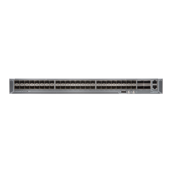
Benefits of ACX5400 Routers | 21 ACX5448, ACX5448-D, and ACX5448-M System Overview | 21 The Juniper Networks ACX5400 Universal Metro Routers are top-of-rack routers with deep packet buffer solutions for metro network or aggregation environments. The ACX5400 router portfolio consists of high-performance, fixed-configuration, 1 U routers that add higher port densities, additional scalability, and improved latency to the ACX Series. - Page 19 Figure 1: ACX5448 Router—Front Figure 2: AC-Powered ACX5448 Router—Rear Figure 3 on page 20 Figure 4 on page 20 show the front and rear, respectively, of a typical ACX5448-D router. Figure 3: ACX5448-D Router—Front Figure 4: AC-Powered ACX5448-D Router—Rear Figure 5 on page 20...
-
Page 20: Benefits Of Acx5400 Routers
800 Gbps. The router provides full metro Ethernet and IP/MPLS VPN services in a space-optimized platform. The ACX5448-D router supports 10-Gigabit, 100-Gigabit, and 100G/200G dense wavelength-division multiplexing (DWDM) ports with a system throughput of up to 800 Gbps. The innovative design of the ACX5448-D helps service providers develop converged packet optical solutions. - Page 21 PSMs. The six fan modules are numbered 0 through 5 from left to right. Similarly, the two PSMs are numbered 0 and 1. Figure 10 on page 23 shows the important components on the front of the ACX5448-D router.
- Page 22 — — The fan modules and PSMs on the ACX5448-D routers are installed in slots on the rear of the chassis. The chassis has six slots for the fan modules and two slots for the PSMs. The six fan modules are numbered 0 through 5 from left to right. Similarly, the two PSMs are numbered 0 and 1.
- Page 23 Figure 13: Front View of the ACX5448-M Router SFP+ ports Console (CON) port — — QSFP28 ports PPS and 10M GPS output ports — — Management (MGMT) port USB port — — Figure 14 on page 24 Figure 15 on page 24 show the important components on the rear of the ACX5448-M routers.
-
Page 24: Acx5400 Router Models
Airflow in (back-to-front) ACX5448-AC-AFO Airflow out (front-to-back) ACX5448-DC-AFO Airflow out (front-to-back) Table 4 on page 25 lists the model numbers for ACX5448-D routers. Table 4: ACX5448-D Router Model Numbers and Description Model Number Power Supply Airflow ACX5448-D-AC-AFI Airflow in (back-to-front) ACX5448-D-DC-AFI... -
Page 25: Field-Replaceable Units In Acx5400 Routers
Do not operate the router with missing FRUs for longer than one minute. NOTE: If you have a Juniper J-Care service contract, register any addition, change, or upgrade of hardware components at https://www.juniper.net/customers/csc/management/updateinstallbase.jsp. Failure to do so can result in significant delays if you need replacement parts. -
Page 26: Hardware Redundancy Of Acx5400 Router Components And Functionality
NOTE: Before removing the optical transceivers, we recommend that you disable the interface using the set interfaces interface-name disable command. Hardware Redundancy of ACX5400 Router Components and Functionality The following hardware components provide redundancy on ACX5400 routers: Power supply modules (PSMs)—The ACX5400 routers have two PSMs. Each PSM provides power to all components in the router. - Page 27 CLI) CLI) CLI) Documentation Additional Information Chassis ACX5448 – Router chassis “Chassis Physical Specifications for ACX5400 ACX5448-D Routers” on page 66 ACX5448-M Routing Routing Engine – Built-in Routing Engine. Engine FPC n Abbreviated name of Value of n is always...
-
Page 28: Acx5400 System Software Overview
Junos OS is installed on an ACX5400 router’s 100-gigabyte (GB) internal solid-state flash drive. The same Junos OS code base that runs on an ACX5400 router also runs on all Juniper Networks QFX and EX Series switches, SRX Series devices, and on MX Series, ACX Series, and PTX Series routers. -
Page 29: Acx5448, Acx5448-D, And Acx5448-M Chassis
The management panel of ACX5400 routers is found on the front of the router. Figure 16 on page 30 shows the management panel components on an ACX5448 router. Figure 16: Management Panel Components on ACX5448 Figure 17 on page 31 shows the management panel components on an ACX5448-D router. - Page 30 Figure 17: Management Panel Components on ACX5448-D Figure 18 on page 31 shows the management panel components on ACX5448-M routers. Figure 18: Management Panel Components on ACX5448-M Management (MGMT) port USB port — — Console (CON) port RESET button —...
-
Page 31: Port Panel Of Acx5400 Routers
— Port Panel of an ACX5448-D Router The port panel of the ACX5448-D router has the following port configurations: Thirty-six 10-Gigabit or 1-Gigabit Ethernet ports (0 through 35, mapped to CLI PIC 0) that operate at 10-Gbps speed with SFP+ transceivers or at 1-Gbps speed when you use SFP optics. - Page 32 — Port, Interface, and PIC Mapping The ACX5448-D does not have a physical FPC or PIC. FPC 0 refers to the router. The ports on the front panel are mapped to logical PICs as follows: Ports 0–35 mapped to PIC 0 (interfaces xe-0/0/0 through xe-/0/0/35)
- Page 33 Default Port Configuration on ACX5448-D By default (factory-default configuration), when you power on an ACX5448-D router, the following port combinations are available: 36 SFP+ ports (ports 0 through 35)—These ports can operate as native 10-Gigabit Ethernet interfaces or as 1-Gigabit Ethernet interfaces when you use 1-gigabit optics.
- Page 34 When you start up the router, the et-0/1/0 interface on port 36 is not created by default. However, the interface et-0/2/0 (on port 38) is always available. You can enable the et-0/1/0 interface (on port 36) by running the set chassis fpc 0 cfp-to-et command and restarting the FPC by executing the restart chassis-control command.
-
Page 35: Port Panel Of An Acx5448-M Router
LED Behavior for CFP2 Ports Table 7 on page 36 summarizes the LED port behavior for CFP2 DCO ports. Table 7: LED behavior for CFP2 ports Mode Color State Description First et- Second et- First et- Second et- port status port status traffic traffic... -
Page 36: Chassis Status Leds On Acx5400 Routers
Six 100-Gigabit Ethernet ports (44 through 49) that support quad small form-factor pluggable 28 (QSFP28) transceivers. You can channelize these ports into four 25-Gbps interfaces using breakout cables (and channelization configuration). These ports also support 40-Gbps speed, when you use QSFP+ optics. You can channelize these 40-Gbps ports into four 10-Gbps interfaces using breakout cables (and channelization configuration). - Page 37 Figure 23: Chassis Status LEDs on an ACX5448-D Router Figure 24: Chassis Status LEDs on an ACX5448-M Router Management (MGMT) port USB port — — Console (CON) port RESET button — — LINK and ST LEDs Status LEDs — —...
- Page 38 Table 8: Chassis Status LEDs on ACX5400 Routers Name Color State Description ALM–Alarm or beacon Unlit The router is halted or there is no alarm. On steadily A major hardware fault has occurred, such as a temperature alarm or power failure, and the router has halted.
-
Page 39: Management Port Leds On Acx5400 Routers
LEDs that indicate link status and link activity (see callout 3 and 4 in Figure 25 on page 40). The right LED indicates status; the left LED indicates link activity. Figure 25: Management Port LEDs on an ACX5448 Router Figure 26: Management Port LEDs on an ACX5448-D Router... -
Page 40: Network Port Leds On Acx5400 Routers
Figure 27: Management Port LEDs on an ACX5448-M Router Management (MGMT) port Status (ST) LED — — Console (CON) port Link activity (LINK) LED — — Table 9 on page 41 describes the management port LEDs. Table 9: Management Port LEDs on ACX5400 Routers Color State Description... - Page 41 Table 10: Network Port LEDs on SFP+ Ports for ACX5400 Routers Mode Color State Description 1-Gigabit Green On or flashing Indicates that the port speed is 10 Gbps, and there Ethernet or is some activity. 10-Gigabit Ethernet Amber On or flashing Indicates that the port speed is 1 Gbps, and there is some activity.
-
Page 42: Fan Status Leds On Acx5400 Routers
25-Gigabit Ethernet interface, and the port is connected using an optical split cable (breakout cable) or a direct attach copper breakout (DACBO) cable. Table 12 on page 43 describes how to interpret CFP2 port LEDs. Table 12: CFP2 Port LEDs on ACX5448-D Routers Mode Color State... -
Page 43: Power Supply Leds On Acx5400 Routers
Table 13: Fan Status LED on ACX5400 Routers Name Color State Description Green On steadily The fan module is operating normally. The system has verified that the module is engaged, that the airflow is in the correct direction, and that the fan is operating correctly. - Page 44 Output status LED — Figure 30 on page 45 shows the location of the LEDs on the ACX5448-D and ACX5448-M PSM (see callouts 1, 2, and 3). Figure 30: AC Power Supply LEDs on an ACX5448-D and ACX5448-M Router Input status LED Fault LED —...
-
Page 45: Dc Power Supply Leds On Acx5400 Routers
Table 14: AC Power Supply Module LEDs on ACX5400 Routers (continued) Color State Description ! (fault) Amber On steadily An error is detected in the PSM. Replace the PSM as soon as possible. To maintain proper airflow through the chassis, leave the PSM installed in the chassis until you are ready to replace NOTE: If the AC OK LED and the DC OK LED are unlit, either the AC power cord is not installed... -
Page 46: Cooling System And Airflow In Acx5448, Acx5448-D, And Acx5448-M Routers
PSM as soon as possible. To maintain proper airflow through the chassis, leave the PSM installed in the chassis until you are ready to replace it. Cooling System and Airflow in ACX5448, ACX5448-D, and ACX5448-M Routers IN THIS SECTION Fan Modules | 48... -
Page 47: Fan Modules
CAUTION: Do not mix fan modules and PSMs with AFO and AFI labels in the same chassis. Fan Modules The fan modules in ACX5400 routers are hot-insertable and hot-removable field-replaceable units (FRUs). The fan modules are installed in the fan module slots on the rear of the router. The ACX5400 routers support six fan modules numbered 0 through 5 from left to right, with each fan module slot having a fan icon next to it. - Page 48 Figure 33 on page 50 AIR IN Juniper Air is pulled You must Azure through the fan install PSMs ACX5448-D-FAN-AFI Blue modules and that have toward the front of AIR IN labels the chassis, from only in those where it is...
-
Page 49: Fan Module And Power Supply Requirement
Figure 33: Air In Airflow Through ACX5400 Chassis—AFI Ports FRUs Figure 34: Air Out Airflow Through ACX5400 Chassis—AFO Ports FRUs Fan Module and Power Supply Requirement Do not mix PSMs with different airflow. If the PSMs are color-coded, ensure they are either all azure blue for the airflow-in (AFI) models or all gold for airflow-out (AFO) models. -
Page 50: Fan Module Status
have AIR IN labels, the color of the PSM handle must be azure blue; if the fan modules have AIR OUT labels, the color of the PSM handle must be gold. Mixing components with different airflows in the same chassis hampers the performance of the cooling system of the router and leads to overheating of the chassis. -
Page 51: Acx5448, Acx5448-D, And Acx5448-M Power System
The system raises an alarm if a fan module fails or if the ambient temperature inside the chassis rises above the acceptable range. If the temperature inside the chassis rises above the threshold temperature, the system shuts down automatically. ACX5448, ACX5448-D, and ACX5448-M Power System IN THIS SECTION... -
Page 52: Ac Power Supply For Acx5400 Routers
AC Power Supply for ACX5400 Routers The ACX5448 AC router operates at 650 W while the ACX5448-D and ACX5448-M AC routers need 850 W. The two power supply modules (PSMs) in ACX5400 routers are hot-removable and hot-insertable field-replaceable units (FRUs). The PSMs are installed in the router at the factory. You can replace the PSMs without powering off the router or disrupting the router function. - Page 53 Figure 36: AC PSM in ACX5448-D and ACX5448-M Routers The PSMs provide FRU-to-port or port-to-FRU airflow depending on the product model you purchase. The PSMs either have labels on the handles that indicate the direction of airflow or have color-coded handles with a fan icon.
-
Page 54: Ac Power Specifications For Acx5400 Routers
Table 19: Airflow Direction in AC PSM for ACX5448-D and ACX5448-M Color of Power Supply Module Power Supply Modules Wattage Direction of Airflow Handle JPSU-850W-AC-AFI 850 W Airflow in (back-to-front) Juniper Azure Blue JPSU-850W-AC-AFO Airflow out Juniper Gold (front-to-back) AC Power Specifications for ACX5400 Routers Table 20 on page 55 describes the AC power specifications for ACX5400 routers. - Page 55 Table 21 on page 56 lists AC power cord specifications provided for each country or region. Table 21: AC Power Cord Specifications Country/Region Electrical Specifications Plug Standards Juniper Model Number Argentina 250 VAC, 10 A, 50 Hz IRAM 2073 Type RA/3 CBL-EX-PWR-C13-AR Australia...
-
Page 56: Dc Power Supply For Acx5400 Routers
(FRUs). The PSMs are installed in the router at the factory. The DC power supply in ACX5448 is 650 W and ACX5448-D and ACX5448-M is 850 W with dual feeds for power resiliency. You can install replacement PSMs without powering off the router or disrupting the router function. - Page 57 Figure 38: DC PSM in an ACX5448 router Figure 39 on page 58 shows the DC PSM in ACX5448-D and ACX5448-M routers. Figure 39: DC PSM in ACX5448-D and ACX5448-M Routers NOTE: The DC PSM in the router has four terminals labeled V–, V–, V+, and V+ for connecting DC power source cables labeled positive (+) and negative (–).
-
Page 58: Dc Power Specifications For Acx5400 Routers
Table 23: Airflow Direction in DC PSM for ACX5448-D and ACX5448-M routers Color of Power Supply Module Power Supply Module Number Wattage Direction of Airflow Handle JPSU-850W-DC-AFI 850 W Airflow in (back-to-front) Juniper Azure Blue JPSU-850W-DC-AFO Airflow out Juniper Gold... -
Page 59: Site Planning, Preparation, And Specifications
C HAPTER Site Planning, Preparation, and Specifications Site Preparation Checklist for ACX5448, ACX5448-D, and ACX5448-M Routers | 63 ACX5448, ACX5448-D, and ACX5448-M Site Guidelines and Requirements | 64 ACX5448, ACX5448-D, and ACX5448-M Network Cable and Transceiver Planning | 73 ACX5448, ACX5448-D, and ACX5448-M Management and Console Port... -
Page 61: Site Preparation Checklist For Acx5448, Acx5448-D, And Acx5448-M Routers
Site Preparation Checklist for ACX5448, ACX5448-D, and ACX5448-M Routers The checklist in Table 25 on page 63 summarizes the tasks you need to perform when preparing a site for an ACX5400 router installation. Table 25: Site Preparation Checklist Item or Task... -
Page 62: Acx5448, Acx5448-D, And Acx5448-M Site Guidelines And Requirements
Choose the length of cable based on the distance between the hardware components being connected. Plan the cable routing and management. ACX5448, ACX5448-D, and ACX5448-M Site Guidelines and Requirements IN THIS SECTION General Site Guidelines | 65... -
Page 63: General Site Guidelines
General Site Guidelines Efficient device operation requires proper site planning and maintenance and proper layout of the equipment, rack or cabinet (if used), and wiring closet. To plan and create an acceptable operating environment for your device and prevent environmentally caused equipment failures: Keep the area around the chassis free from dust and conductive material, such as metal flakes. -
Page 64: Chassis Physical Specifications For Acx5400 Routers
Table 27 on page Table 28 on page 67, and Table 29 on page 67 summarize the physical specifications of ACX5448, ACX5448-D, and ACX5448-M routers and their components. Table 27: Physical Specifications for an ACX5448 Router Chassis and FRUs Item Height Width... -
Page 65: Acx5400 Router Environmental Requirements And Specifications
Table 28: Physical Specifications for an ACX5448-D Router Chassis and FRUs Item Height Width Depth Weight ACX5448-D 1.70 in. (4.33 cm) 17.26 in. Without fan module and PSM With FRUs installed: (43.84 cm) handles: 20.29 in. (51.53 cm) 23.14 lb (10.5 kg) -
Page 66: Acx5400 Grounding Cable And Lug Specifications
Maintain ambient airflow for normal router operation. If the airflow is blocked or restricted, or if the intake air is too warm, the router might overheat, leading to the router temperature monitor shutting down the device to protect the hardware components. Table 30 on page 68 provides the required environmental conditions for normal router operation. - Page 67 Minimum recommendations are 12 AWG (2.5 mm²) stranded wire, 60° C wire, or as permitted by local code. For ACX5448-D and ACX5448-M routers, the grounding lug required is a Panduit LCD10-10A-L or equivalent. The grounding lug accommodates 12 AWG (2.5 mm²) , 90° C temperature-rated stranded...
-
Page 68: Clearance Requirements For Airflow And Hardware Maintenance For Acx5400 Routers
When planning the site for installing an ACX5400 router, you must allow sufficient clearance around the installed chassis (see Figure 40 on page 70 Figure 41 on page 70). Figure 40: Clearance Requirements for Airflow and Hardware Maintenance for ACX5448 and ACX5448-D Routers 24 in. 21.81 in. 24.0 in. -
Page 69: Cabinet Requirements For Acx5400 Routers
For the cooling system to function properly, the airflow around the chassis must be unrestricted. See “Cooling System and Airflow in ACX5448, ACX5448-D, and ACX5448-M Routers” on page 47 for more information about the airflow through the chassis. If you are mounting an ACX5400 router in a rack or cabinet with other equipment, ensure that the exhaust from other equipment does not blow into the intake vents of the chassis. -
Page 70: Rack Requirements For Acx5400 Routers
Table 31: Cabinet Requirements for ACX5400 Routers (continued) Cabinet Requirement Guidelines Cabinet airflow requirements When you mount the router in a cabinet, ensure that ventilation through the cabinet is sufficient to prevent overheating. Ensure that the cool air supply you provide through the cabinet adequately dissipates the thermal output of the router (or routers). -
Page 71: Acx5448, Acx5448-D, And Acx5448-M Network Cable And Transceiver Planning
Ensure that the rack is strong enough to support the weight of the router. The fully configured ACX5448 router weighs about 22.48 lb (10.2 kg), the ACX5448-D router weighs 23.14 lb (10.5 kg), and the ACX5448-M router weighs 26.12 lb (11.85 kg). -
Page 72: Determining Transceiver Support For Acx5400
The 40-Gigabit Ethernet QSFP+ and 100-Gigabit Ethernet QSFP28 transceivers that are used in ACX Series routers use 12-ribbon multimode fiber crossover cables with female MPO connectors (SR4 optics only). The fiber can be either OM3 or OM4. Juniper Networks does not sell these cables. CAUTION: To maintain agency approvals, use only a properly constructed, shielded cable. - Page 73 Table 33 on page 75 describes the signals on each fiber. Table 34 on page 75 shows the pin to pin connections for proper polarity. Table 33: QSFP+ MPO Cable Signals Fiber Signal Tx0 (Transmit) Tx1 (Transmit) Tx2 (Transmit) Tx3 (Transmit) Unused Unused Unused...
-
Page 74: Calculating Power Budget And Power Margin For Fiber-Optic Cables
You can use the Hardware Compatibility Tool to find information about the pluggable transceivers supported on your Juniper Networks device. To calculate the power budget and power margin, perform the following tasks: Calculating Power Budget for Fiber-Optic Cable | 76... -
Page 75: Calculating Power Margin For Fiber-Optic Cable
The following hypothetical power budget equation uses values measured in decibels (dB) and decibels referred to one milliwatt (dBm): – P = –15 dBm – (–28 dBm) = 13 dB Calculating Power Margin for Fiber-Optic Cable After calculating a link's power budget, you can calculate the power margin (P ), which represents the amount of power available after subtracting attenuation or link loss (LL) from the power budget (P ). -
Page 76: Understanding Fiber-Optic Cable Signal Loss, Attenuation, And Dispersion
(2 km @ 1 dB/km, or 2 dB) and loss for five connectors (0.5 dB per connector, or 2.5 dB) and two splices (0.5 dB per splice, or 1 dB) as well as higher-order mode losses (0.5 dB). The power margin (P ) is calculated as follows: –... -
Page 77: Attenuation And Dispersion In Fiber-Optic Cable
light at different angles. Light rays travel in jagged lines through a multimode fiber, causing signal dispersion. When light traveling in the fiber core radiates into the fiber cladding, higher-order mode loss results. Together these factors limit the transmission distance of multimode fiber compared with single-mode fiber. -
Page 78: Acx5448, Acx5448-D, And Acx5448-M Management And Console Port Specifications And Pinouts
ACX5448, ACX5448-D, and ACX5448-M Management and Console Port Specifications and Pinouts IN THIS SECTION Management Cable Specifications for ACX5400 Routers | 80 Management Port Connector Pinout Information for ACX Series Routers | 80 Console or Auxiliary Port Connector Pinout on ACX Series Routers | 81... -
Page 79: Console Or Auxiliary Port Connector Pinout On Acx Series Routers
Table 37 on page 81 provides the pinout information for the RJ-45 connector for the management port. Table 37: Management Port Connector Pinout Information Description Direction TRD[0]- In/Out TRD[0]+ In/Out TRD[1]- In/Out TRD[1]+ In/Out TRD[2]- In/Out TRD[2]+ In/Out TRD[3]- In/Out TRD[3]+ In/Out Console or Auxiliary Port Connector Pinout on ACX Series Routers... -
Page 80: Usb Port Specifications For An Acx Series Router
1588 CPU Clear to Send Routing Engine USB Port Specifications for an ACX Series Router The following Juniper Networks USB flash drives have been tested and are officially supported for the USB port on all ACX Series routers: RE-USB-1G-S RE-USB-2G-S... - Page 81 Unpacking and Mounting ACX5448, ACX5448-D, and ACX5448-M | 86 Connect ACX5448, ACX5448-D, and ACX5448-M to Power | 95 Connect ACX5448, ACX5448-D, and ACX5448-M to External Devices | 106 Perform Initial Software Configuration for the ACX5448, ACX5448-D, and ACX5448-M Routers | 109...
-
Page 83: Acx5448, Acx5448-D, And Acx5448-M Installation Overview
“Connect AC Power to an ACX5400 Router” on page 98 “Connect DC Power to an ACX5400 Router” on page 102, as required. c. Registering Products—Mandatory for Validating SLAs “Perform Initial Software Configuration for the ACX5448, ACX5448-D, and ACX5448-M Routers” on page 109. -
Page 84: Unpacking And Mounting Acx5448, Acx5448-D, And Acx5448-M
Unpacking and Mounting ACX5448, ACX5448-D, and ACX5448-M IN THIS SECTION Unpack an ACX5400 Router | 86 Mount an ACX5400 Router in a Rack or Cabinet | 87 Unpack an ACX5400 Router The ACX5400 router chassis is a rigid sheet-metal structure that houses the hardware components. We ship the ACX5400 router in a cardboard carton, secured with foam packing material. -
Page 85: Mount An Acx5400 Router In A Rack Or Cabinet
Six fan modules 7. Save the shipping carton and packing materials in case you need to move or ship the router later. Table 39: ACX5400 Router Parts List Component Quantity Chassis with six fan modules and two PSMs AC power cord (generic, type C13 coupler) (only with AC-powered ACX5400 routers) AC Power cord retainer clip (only with AC-powered ACX5400 routers) -
Page 86: Before You Begin Rack Installation
2. Verify that the site meets the requirements described in “Site Preparation Checklist for ACX5448, ACX5448-D, and ACX5448-M Routers” on page 3. Place the rack in its permanent location, allowing adequate clearance for airflow and maintenance, and secure it to the building structure. -
Page 87: Install The Acx5400 Router In The Rack
3. Align the holes in the front-mounting rails with the holes on the side of the chassis (see Figure 42 on page 90 for ACX5448, Figure 43 on page 90 for ACX5448-D, and Figure 44 on page 90 for ACX5448-M). - Page 88 Figure 42: Install the Mounting Rails on an ACX5448 Router Figure 43: Install the Mounting Rails on an ACX5448-D Router Figure 44: Install the Mounting Rails on an ACX5448-M Router 4. Using a Phillips (+) number 2 screwdriver, secure the mounting rails to the chassis using the mounting screws.
- Page 89 Figure 45: Install the ACX5448 Router in a Four-Post Rack Figure 46: Install the ACX5448-D Router in a Four-Post Rack Figure 47: Install the ACX5448-M Router in a Four-Post Rack 7. Install mounting screws into each of the front-mounting bracket holes aligned with the rack, starting from the bottom, and secure them tightly.
- Page 90 Figure 48: ACX5448 Router Secured by Front-Mounting Brackets Figure 49: ACX5448-D Router Secured by Front-Mounting Brackets Figure 50: ACX5448-M Router Secured by Front-Mounting Brackets 8. On the rear of the chassis, slide the rear-mounting blades on either side of the chassis until the...
- Page 91 Figure 51: Install the Rear-Mounting Blades on an ACX5448 Router Figure 52: Install the Mounting Blades on an ACX5448-D Router Figure 53: Install the Rear-Mounting Blades on an ACX5448-M Router 9. Install mounting screws into each of the rear-mounting bracket holes aligned with the rack, starting from the bottom, and secure them tightly.
- Page 92 Figure 54: ACX5448 Router Installed in the Rack Figure 55: ACX5448-D Router Installed in the Rack Figure 56: ACX5448-M Router Installed in the Rack...
-
Page 93: Connect Acx5448, Acx5448-D, And Acx5448-M To Power
Figure 57 on page Figure 58 on page 95, and Figure 59 on page 96 show the grounding points on ACX5400 routers. Figure 57: Grounding Points on the ACX5448 Router Figure 58: Grounding Points on the ACX5448-D Router... - Page 94 Minimum recommendations are 12 AWG (2.5 mm²) stranded wire, 60° C wire for the ACX5448 router and 12 AWG (2.5 mm²), 90° C temperature-rated stranded wire for the ACX5448-D and ACX5448-M routers. To ground the ACX5400 router: 1. Verify that a licensed electrician has attached the cable lug provided with the router to the grounding cable.
- Page 95 5. Place the grounding cable lug over the grounding points on the side of the chassis (see Figure 60 on page 97 for ACX5448 and ACX5448-D routers and Figure 61 on page 97 for the ACX5448-M router). Figure 60: Connect the Grounding Cable to the ACX5448 or ACX5548-D Router Figure 61: Connect the Grounding Cable to the ACX5448-M Router 6.
-
Page 96: Connect Ac Power To An Acx5400 Router
Connect AC Power to an ACX5400 Router The power supply module (PSM) in an ACX5400 router is a hot-removable and hot-insertable field-replaceable unit (FRU). You can remove and replace it without powering off the router or disrupting routing functions. Ensure that you have a power cord appropriate for your geographical location available to connect AC power to the router. - Page 97 NOTE: Each power supply must be connected to a dedicated AC power feed and a dedicated customer-site 2-pole circuit breaker. We recommend that you use a dedicated customer-site circuit breaker rated for 20 A (110 VAC) or 16 A (220 VAC) minimum, or as required by local code.
- Page 98 10. Power on the source power supply. 11. Repeat Step through Step for the installing the remaining PSM. Figure 64: Connect an AC Power Cord to an ACX5448 To connect AC power to ACX5448-D and ACX5448-M routers:...
- Page 99 4. Push the power cord retainer onto the power cord. Figure 65 on page 101 shows the power cord retainer installed on the AC PSM for the ACX5448-D and ACX5448-M router and Figure 66 on page 102 shows how to connect an AC power cord to an ACX5448-D or ACX5448-M router.
-
Page 100: Connect Dc Power To An Acx5400 Router
Figure 66: : Connect an AC Power Cord to an ACX5448-D or ACX5448-M router 5. Power on the power supply at source. Connect DC Power to an ACX5400 Router The power supply module (PSM) in an ACX5400 router is a hot-removable and hot-insertable field-replaceable unit (FRU). - Page 101 CAUTION: Before you connect power to the router, a licensed electrician must attach a cable lug to the grounding and power cables that you supply. A cable with an incorrectly attached lug can damage the router (for example, by causing a short circuit).
- Page 102 3. Ensure that the input 2-pole circuit breaker is open so that the voltage across the DC power source cable leads is 0 V and that the cable leads do not become active while you are connecting DC power. NOTE: The V+ terminals are referred to as +RTN, and V–...
- Page 103 c. Tighten the screws on the PSM terminals until snug using the screwdriver. Do not overtighten—apply between 5 in-lb (0.56 Nm) and 6 in-lb (0.68 Nm) of torque to the screws. CAUTION: The V+ terminals are shunted internally, as are the V– terminals. The same polarity terminal can be wired together from the same source to provide an additional current path in a higher power chassis.
-
Page 104: Connect Acx5448, Acx5448-D, And Acx5448-M To External Devices
Connect ACX5448, ACX5448-D, and ACX5448-M to External Devices IN THIS SECTION Connect an ACX5400 Router to a Management Console | 106 Connect an ACX5400 Router to a Network for Out-of-Band Management | 107 Connect an ACX5400 Router to External Clocking and Timing Devices | 108 Connect an ACX5400 Router to a Management Console The ACX5400 routers have a console port with an RJ-45 connector. -
Page 105: Connect An Acx5400 Router To A Network For Out-Of-Band Management
You must configure the management ports before you can successfully connect to the ACX5400 router using these ports. See “Perform Initial Software Configuration for the ACX5448, ACX5448-D, and ACX5448-M Routers” on page 109. Ensure that you have an appropriate cable available. See “ACX5448, ACX5448-D, and ACX5448-M Network... -
Page 106: Connect An Acx5400 Router To External Clocking And Timing Devices
2. Connect the other end of the cable to the management PC (see Figure 70 on page 108). Figure 70: Connect an ACX5400 Router to a Network for Out-of-Band Management Management PC Management Network MGMT Management PC To Management Port (on Device) Management PC Connect an ACX5400 Router to External Clocking and Timing Devices... -
Page 107: Perform Initial Software Configuration For The Acx5448, Acx5448-D, And Acx5448-M Routers
Perform Initial Software Configuration for the ACX5448, ACX5448-D, and ACX5448-M Routers You must perform the initial configuration of the ACX5400 router through the console port using the command-line interface (CLI). Before you begin connecting and configuring an ACX5400 router, set the following parameter values on the console server or PC: Baud Rate—9600... - Page 108 6. (Optional) Configure the name of the router. If the name includes spaces, enclose the name in quotation marks (“ ”). [edit] root@# set system host-name host-name 7. Configure the default gateway. [edit] root@# set routing-options static route default next-hop address 8.
- Page 109 root@# commit...
-
Page 110: Maintaining Acx5448, Acx5448-D, And Acx5448-M Components
C HAPTER Maintaining Components Maintaining ACX5448, ACX5448-D, and ACX5448-M Components | 115 Removing the ACX5448, ACX5448-D, or ACX5448-M Router | 136... -
Page 112: Replace An Acx5400 Fan Module
Maintaining ACX5448, ACX5448-D, and ACX5448-M Components IN THIS SECTION Replace an ACX5400 Fan Module | 115 Replace an ACX5400 AC Power Supply Module | 118 Replace an ACX5400 DC Power Supply Module | 122 Replace an SFP+ Transceiver | 127... - Page 113 Before you remove a fan module from an ACX5400 router, ensure that you have taken the necessary precautions to prevent electrostatic discharge (ESD) damage (see “Prevention of Electrostatic Discharge Damage” on page 191). Ensure that you have the following parts and tools available to remove a fan module from an ACX5400 router: ESD grounding strap Antistatic bag or an antistatic mat...
-
Page 114: Install A Fan Module In An Acx5400 Router
NOTE: When you remove a fan module, the CLI message Fan/Blower is Absent is logged in the system log, and Junos OS raises a minor alarm. Install a Fan Module in an ACX5400 Router The fan modules in an ACX5400 router are hot-removable and hot-insertable field replaceable units (FRUs): you can remove and replace them without powering off the router or disrupting routing functions. -
Page 115: Replace An Acx5400 Ac Power Supply Module
ACX5400 product model that supports the same airflow type. See “Cooling System and Airflow in ACX5448, ACX5448-D, and ACX5448-M Routers” on page 47 for more information. 4. Using a Phillips screwdriver, turn the locking screw until it is tight. - Page 116 Before you remove a PSM from a router, ensure that you have taken the necessary precautions to prevent electrostatic discharge (ESD) damage (see “Prevention of Electrostatic Discharge Damage” on page 191). Ensure that you have the following parts and tools available to remove a PSM from a router: ESD grounding strap Antistatic bag or an antistatic mat Phillips (+) screwdriver, number 2...
-
Page 117: Install An Ac Power Supply Module In An Acx5400 Router
Figure 73: Remove PSM from an ACX5448 Router Figure 74: Remove PSM from an ACX5448-D or ACX5448-M Router Install an AC Power Supply Module in an ACX5400 Router The PSMs in an ACX5400 router are hot-removable and hot-insertable field-replaceable units (FRUs): you can remove and replace them without powering off the router or disrupting routing functions. - Page 118 CAUTION: Verify that the direction of the arrow on the PSM handle matches the direction of airflow in the chassis. Ensure that each PSM you install in the chassis has the same airflow direction. If you install PSMs with two different airflow directions, Junos OS raises an alarm, and the status (ALM) LED blinks amber.
-
Page 119: Replace An Acx5400 Dc Power Supply Module
Figure 77: Install an AC PSM in an ACX5448-D or ACX5448-M Router Figure 78: Install an AC Power Cord in an ACX5448-D or ACX5448-M router NOTE: Each PSM must be connected to a dedicated power source outlet. NOTE: If you have a Juniper J-Care service contract, register any addition, change, or upgrade of hardware components at https://www.juniper.net/customers/csc/management/updateinstallbase.jsp... -
Page 120: Remove An Acx5400 Dc Power Supply Module
Remove an ACX5400 DC Power Supply Module Before you remove a power supply module (PSM), be aware of the following: NOTE: The minimum required number of PSMs must be present in the router at all times. WARNING: Before performing DC power procedures, ensure that power is removed from the DC circuit. -
Page 121: Install An Acx5400 Dc Power Supply Module
5. Remove the clear plastic cover protecting the terminal studs on the faceplate. 6. Using a socket screw driver, remove the screw from each of the DC power terminals (see Figure 79 on page 124). 7. Remove the cable lugs from the terminals. 8. - Page 122 To install a DC PSM (see Figure 81 on page 126): 1. Ensure that the voltage across the DC power source cable leads is 0 V and that there is no chance that the cable leads might become active during installation. 2.
- Page 123 10. Observe the status LED on the power supply faceplate. If the PSM is correctly installed and functioning normally, the status LED lights green steadily. Figure 81: Install a DC PSM in an ACX5448 Router Figure 82: Install a DC PSM in an ACX5448-D or ACX5448-M Router Figure 83: Connect the DC Power Cables...
-
Page 124: Replace An Sfp+ Transceiver
Replace an SFP+ Transceiver IN THIS SECTION Remove an SFP+ Transceiver | 127 Install an SFP+ Transceiver | 128 Small form-factor pluggable plus transceivers (SFP+) are enhanced SFP transceivers that provide support for data rates of up to 10 Gbps for fiber-optic or copper interfaces. SFP+ transceivers are hot-insertable and hot-removable. -
Page 125: Install An Sfp+ Transceiver
WARNING: Do not look directly into a fiber-optic transceiver or into the ends of fiber-optic cables. Fiber-optic transceivers and fiber-optic cables connected to a transceiver emit laser light that can damage your eyes. 5. Pull the ejector handle out from the transceiver to unlock the transceiver. CAUTION: Make sure that you open the ejector handle completely until you hear it click. -
Page 126: Replace A Qsfp28 Transceiver
3. Verify that each transceiver is covered by a rubber safety cap. If it is not, cover the transceiver with a safety cap. 4. Carefully align the transceiver with the slots in the component. The connectors should face the component. 5. -
Page 127: Remove A Qsfp28 Transceiver
Remove a QSFP28 Transceiver To remove a QSFP28 transceiver (see Figure 85 on page 131): 1. Place an electrostatic bag or antistatic mat on a flat, stable surface to receive the QSFP28 transceiver. Have ready a rubber safety cap for the QSFP28 transceiver and the cable. 2. -
Page 128: Install A Qsfp28 Transceiver
Figure 85: 28-Gbps Quad Small Form-Factor Pluggable (QSFP28) Transceiver Install a QSFP28 Transceiver To install a replacement QSFP28 transceiver: 1. Wrap and fasten one end of the ESD grounding strap around your bare wrist, and connect the other end of the strap to the ESD point on the chassis. 2. -
Page 129: Replacing A Cfp2 Transceiver
excess cable out of the way in a neatly coiled loop in the cable management system. Placing fasteners on the loop helps to maintain its shape. CAUTION: Do not let fiber-optic cable hang free from the connector. Do not allow fastened loops of cable to dangle, which stresses the cable at the fastening point. -
Page 130: Removing A Cfp2 Transceiver
Removing a CFP2 Transceiver CFP2 transceivers are hot-insertable and hot-removable. Removing a CFP2 transceiver does not interrupt the device functions, but the removed CFP2 transceiver no longer receives or transmits data. Figure 86: Form-Factor Pluggable (CFP2) Ejector Open Locking pin Closed To remove a CFP2 transceiver (see Figure 86 on page... -
Page 131: Installing A Cfp2 Transceiver
CAUTION: Do not leave a fiber-optic transceiver uncovered except when inserting or removing cable. The safety cap keeps the port clean and prevents accidental exposure to laser light. 5. Arrange the cable in the cable management system to prevent it from dislodging or developing stress points. - Page 132 NOTE: When inserting the C form-factor pluggable 2 (CFP2) transceiver, ensure that the transceiver sits tightly in the port. You hear a distinct click sound when the latch locks into the corresponding port. The latch must be fully engaged in the corresponding port for the CFP2 transceiver to function properly.
-
Page 133: Maintaining Fiber-Optic Cables
Maintaining Fiber-Optic Cables Fiber-optic cables connect to optical transceivers that are installed in Juniper Networks devices. To maintain fiber-optic cables: When you unplug a fiber-optic cable from a transceiver, place rubber safety caps over the transceiver and on the end of the cable. -
Page 134: Power Off An Acx5400 Router
Power Off an ACX5400 Router Before you power off an ACX5448 router: Ensure that you have taken the necessary precautions to prevent electrostatic discharge (ESD) damage. “Prevention of Electrostatic Discharge Damage” on page 191. Ensure that you do not need to forward traffic through the router. Ensure that you have the following parts and tools available to power off the router: An ESD grounding strap An external management device such as a PC... -
Page 135: Remove An Acx5400 Router From A Rack Or Cabinet
Operating system halted. Please press any key to reboot. 3. Wait until a message appears on the console confirming that the operating system has halted. For more information about the command, see the Explorer. 4. Wrap and fasten one end of the ESD grounding strap around your bare wrist, and connect the other end of the strap to the ESD point on the chassis. - Page 136 Ensure that the rack is stable and secured to the building. Ensure that there is enough space to place the removed router in its new location and along the path to the new location. Read “General Safety Guidelines and Warnings” on page 159.
-
Page 137: Troubleshooting The Acx5448, Acx5448-D, And Acx5448-M Routers
C HAPTER Troubleshooting Hardware Troubleshooting the ACX5448, ACX5448-D, and ACX5448-M Routers | 143... -
Page 139: Alarm Types And Severity Classes On Acx Series Routers
Troubleshooting the ACX5448, ACX5448-D, and ACX5448-M Routers IN THIS SECTION Alarm Types and Severity Classes on ACX Series Routers | 143 Alarm Types and Severity Classes on ACX Series Routers Before monitoring alarms on the router, become familiar with the terms defined in Table 41 on page 143. -
Page 140: Alarm Severity Classes
Alarm Severity Classes Alarms on ACX Series routers have two severity classes: Major (steady red)—Indicates a critical situation on the router that has resulted from one of the following conditions. A red alarm condition requires immediate action. One or more hardware components have failed. One or more hardware components have exceeded temperature thresholds. -
Page 141: Contacting Customer Support And Returning The Chassis Or Components
C HAPTER Contacting Customer Support and Returning the Chassis or Components Contacting Customer Support and Returning the Chassis or Components | 147... -
Page 143: Returning A Hardware Component To Juniper Networks, Inc
Do not return any component to Juniper Networks, Inc. unless you have first obtained an RMA number. Juniper Networks, Inc. reserves the right to refuse shipments that do not have an RMA. Refused shipments are returned to the customer by collect freight. -
Page 144: How To Locate The Serial Number On An Acx5400 Router Or Component
Locate the Serial Number ID Label on an ACX5400 Fan Module | 153 If you are returning a router or component to Juniper Networks for repair or replacement, you must locate the serial number of the router or component. You must provide the serial number to the Juniper Networks Technical Assistance Center (JTAC) when you contact them to obtain a Return Materials Authorization (RMA). -
Page 145: List The Chassis And Component Details Using The Cli
List the Chassis and Component Details Using the CLI To list the components and serial numbers of ACX5448, ACX5448-D, and ACX5448-M routers, use the show chassis hardware CLI operational mode command. The show chassis hardware output for ACX5448: user@device> show chassis hardware... - Page 146 2x200GE CFP2-DCO PIC 2 BUILTIN BUILTIN 2x200GE CFP2-DCO Fan Tray 0 Fan Tray ACX5448-D 0, Front to Back Airflow - AFO Fan Tray 1 Fan Tray ACX5448-D 1, Front to Back Airflow - AFO Fan Tray 2 Fan Tray ACX5448-D 2,...
-
Page 147: Locate The Chassis Serial Number Id Label On An Acx5400 Router
FPC 0 BUILTIN BUILTIN FPC BUILTIN MIC 0 44x1GE/44x10GE MACSEC PIC 0 BUILTIN BUILTIN 44x1GE/44x10GE MACSEC Xcvr 6 REV 01 740-031980 2013057700056 SFP+-10G-SR MIC 1 24x10/25GE 6x40/100GE PIC 1 BUILTIN BUILTIN 24x10/25GE 6x40/100GE Fan Tray 0 Fan Tray ACX5448-M 0, Front to Back Airflow - AFO Fan Tray 1 Fan Tray ACX5448-M 1,... -
Page 148: Locate The Serial Number Id Labels On Acx5400 Power Supply Modules
Figure 88: Location of the Serial Number ID Label on an ACX5448-D router Serial number ID label Figure 89: Location of the Serial Number ID Label on an ACX5448-M router Serial number ID label Locate the Serial Number ID Labels on ACX5400 Power Supply Modules The power supply modules (PSMs) installed in an ACX5400 are field-replaceable units (FRUs). -
Page 149: Locate The Serial Number Id Label On An Acx5400 Fan Module
153. Figure 92: ACX5448 DC PSM Serial Number Location Serial number ID label Figure 93: DC PSM Serial Number Location for ACX5448-D and ACX5448-M Routers Serial number ID label Locate the Serial Number ID Label on an ACX5400 Fan Module The fan modules installed in an ACX5400 are field-replaceable units (FRUs). -
Page 150: Contacting Customer Support To Obtain Return Material Authorization
Serial number ID label Contacting Customer Support to Obtain Return Material Authorization If you are returning a device or hardware component to Juniper Networks for repair or replacement, obtain a Return Material Authorization (RMA) number from Juniper Networks Technical Assistance Center (JTAC). -
Page 151: Guidelines For Packing Hardware Components For Shipment
If you are contacting JTAC by telephone, enter your 12-digit service request number followed by the pound (#) key for an existing case, or press the star (*) key to be routed to the next available support engineer. The support representative validates your request and issues an RMA number for return of the component. Guidelines for Packing Hardware Components for Shipment To pack and ship individual components: When you return components, make sure that they are adequately protected with packing materials... - Page 152 C HAPTER Safety and Compliance Information General Safety Guidelines and Warnings | 159 Definitions of Safety Warning Levels | 160 Qualified Personnel Warning | 163 Warning Statement for Norway and Sweden | 164 Fire Safety Requirements | 164 Installation Instructions Warning | 166 Restricted Access Warning | 167 Ramp Warning | 169 Rack-Mounting and Cabinet-Mounting Warnings | 170...
- Page 153 Multiple Power Supplies Disconnection Warning | 206 TN Power Warning | 207 Action to Take After an Electrical Accident | 207 Agency Approvals for ACX5448, ACX5448-D, and ACX5448-M Routers | 208 Compliance Statements for NEBS | 209 Compliance Statements for EMC Requirements | 209...
-
Page 154: General Safety Guidelines And Warnings
General Safety Guidelines and Warnings The following guidelines help ensure your safety and protect the device from damage. The list of guidelines might not address all potentially hazardous situations in your working environment, so be alert and exercise good judgment at all times. Perform only the procedures explicitly described in the hardware documentation for this device. -
Page 155: Definitions Of Safety Warning Levels
Always ensure that all modules, power supplies, and cover panels are fully inserted and that the installation screws are fully tightened. Definitions of Safety Warning Levels The documentation uses the following levels of safety warnings (there are two Warning formats): NOTE: You might find this information helpful in a particular situation, or you might overlook this important information if it was not highlighted in a Note. - Page 157 WARNING: This symbol means danger. You are in a situation that could cause bodily injury. Before you work on any equipment, be aware of the hazards involved with electrical circuitry and be familiar with standard practices for preventing accidents. Waarschuwing Dit waarschuwingssymbool betekent gevaar. U verkeert in een situatie die lichamelijk letsel kan veroorzaken.
-
Page 158: Qualified Personnel Warning
Varning! Denna varningssymbol signalerar fara. Du befinner dig i en situation som kan leda till personskada. Innan du utför arbete på någon utrustning måste du vara medveten om farorna med elkretsar och känna till vanligt förfarande för att förebygga skador. Qualified Personnel Warning WARNING: Only trained and qualified personnel should install or replace the device. -
Page 159: Warning Statement For Norway And Sweden
In addition, you should establish procedures to protect your equipment in the event of a fire emergency. Juniper Networks products should be installed in an environment suitable for electronic equipment. We recommend that fire suppression equipment be available in the event of a fire in the vicinity of the equipment and that all local fire, safety, and electrical codes and ordinances be observed when you install and operate your equipment. - Page 160 To keep warranties effective, do not use a dry chemical fire extinguisher to control a fire at or near a Juniper Networks device. If a dry chemical fire extinguisher is used, the unit is no longer eligible for coverage under a service agreement.
-
Page 161: Installation Instructions Warning
Installation Instructions Warning WARNING: Read the installation instructions before you connect the device to a power source. Waarschuwing Raadpleeg de installatie-aanwijzingen voordat u het systeem met de voeding verbindt. Varoitus Lue asennusohjeet ennen järjestelmän yhdistämistä virtalähteeseen. Attention Avant de brancher le système sur la source d'alimentation, consulter les directives d'installation. -
Page 162: Restricted Access Warning
Restricted Access Warning... - Page 163 WARNING: This unit is intended for installation in restricted access areas. A restricted access area is an area to which access can be gained only by service personnel through the use of a special tool, lock and key, or other means of security, and which is controlled by the authority responsible for the location.
-
Page 164: Ramp Warning
¡Atención! Esta unidad ha sido diseñada para instalarse en áreas de acceso restringido. Área de acceso restringido significa un área a la que solamente tiene acceso el personal de servicio mediante la utilización de una herramienta especial, cerradura con llave, o algún otro medio de seguridad, y que está... -
Page 165: Rack-Mounting And Cabinet-Mounting Warnings
Rack-Mounting and Cabinet-Mounting Warnings Ensure that the rack or cabinet in which the device is installed is evenly and securely supported. Uneven mechanical loading could lead to a hazardous condition. - Page 167 De onderstaande richtlijnen worden verstrekt om uw veiligheid te verzekeren: De Juniper Networks switch moet in een stellage worden geïnstalleerd die aan een bouwsel is verankerd. Dit toestel dient onderaan in het rek gemonteerd te worden als het toestel het enige in het rek is.
- Page 168 Les directives ci-dessous sont destinées à assurer la protection du personnel: Le rack sur lequel est monté le Juniper Networks switch doit être fixé à la structure du bâtiment. Si cette unité constitue la seule unité montée en casier, elle doit être placée dans le bas.
- Page 169 Il Juniper Networks switch deve essere installato in un telaio, il quale deve essere fissato alla struttura dell'edificio. Questa unità deve venire montata sul fondo del supporto, se si tratta dell'unica unità da montare nel supporto. Quando questa unità viene montata in un supporto parzialmente pieno, caricare il supporto dal basso all'alto, con il componente più...
- Page 170 El Juniper Networks switch debe instalarse en un bastidor fijado a la estructura del edificio. Colocar el equipo en la parte inferior del bastidor, cuando sea la única unidad en el mismo. Cuando este equipo se vaya a instalar en un bastidor parcialmente ocupado, comenzar la instalación desde la parte inferior hacia la superior colocando el equipo más pesado...
-
Page 171: Grounded Equipment Warning
Grounded Equipment Warning WARNING: The device is intended to be grounded. During normal use, ensure that you have connected earth ground to the chassis. Waarschuwing Deze apparatuur hoort geaard te worden Zorg dat de host-computer tijdens normaal gebruik met aarde is verbonden. Varoitus Tämä... -
Page 172: Radiation From Open Port Apertures Warning
Radiation from Open Port Apertures Warning WARNING: Because invisible radiation might be emitted from the aperture of the port when no fiber cable is connected, avoid exposure to radiation and do not stare into open apertures. Waarschuwing Aangezien onzichtbare straling vanuit de opening van de poort kan komen als er geen fiberkabel aangesloten is, dient blootstelling aan straling en het kijken in open openingen vermeden te worden. -
Page 173: Laser And Led Safety Guidelines And Warnings
Class 1 LED Product Warning | 180 Laser Beam Warning | 181 Juniper Networks devices are equipped with laser transmitters, which are considered a Class 1 Laser Product by the U.S. Food and Drug Administration and are evaluated as a Class 1 Laser Product per EN 60825-1 requirements. -
Page 174: Class 1 Laser Product Warning
Class 1 Laser Product Warning WARNING: Class 1 laser product. Waarschuwing Klasse-1 laser produkt. Varoitus Luokan 1 lasertuote. Attention Produit laser de classe I. Warnung Laserprodukt der Klasse 1. Avvertenza Prodotto laser di Classe 1. Advarsel Laserprodukt av klasse 1. Aviso Produto laser de classe 1. -
Page 175: Class 1 Led Product Warning
Class 1 LED Product Warning WARNING: Class 1 LED product. Waarschuwing Klasse 1 LED-product. Varoitus Luokan 1 valodiodituote. Attention Alarme de produit LED Class I. Warnung Class 1 LED-Produktwarnung. Avvertenza Avvertenza prodotto LED di Classe 1. Advarsel LED-produkt i klasse 1. Aviso Produto de classe 1 com LED. -
Page 176: Maintenance And Operational Safety Guidelines And Warnings
Laser Beam Warning WARNING: Do not stare into the laser beam or view it directly with optical instruments. Waarschuwing Niet in de straal staren of hem rechtstreeks bekijken met optische instrumenten. Varoitus Älä katso säteeseen äläkä tarkastele sitä suoraan optisen laitteen avulla. Attention Ne pas fixer le faisceau des yeux, ni l'observer directement à... - Page 177 Operating Temperature Warning | 187 Product Disposal Warning | 189 While performing the maintenance activities for devices, observe the following guidelines and warnings:...
-
Page 178: Battery Handling Warning
Battery Handling Warning WARNING: Replacing a battery incorrectly might result in an explosion. Replace a battery only with the same or equivalent type recommended by the manufacturer. Dispose of used batteries according to the manufacturer's instructions. Waarschuwing Er is ontploffingsgevaar als de batterij verkeerd vervangen wordt. Vervang de batterij slechts met hetzelfde of een equivalent type dat door de fabrikant aanbevolen is. -
Page 179: Jewelry Removal Warning
Jewelry Removal Warning... - Page 180 WARNING: Before working on equipment that is connected to power lines, remove jewelry, including rings, necklaces, and watches. Metal objects heat up when connected to power and ground and can cause serious burns or can be welded to the terminals. Waarschuwing Alvorens aan apparatuur te werken die met elektrische leidingen is verbonden, sieraden (inclusief ringen, kettingen en horloges) verwijderen.
-
Page 181: Lightning Activity Warning
se conectan a la alimentación y a tierra, lo que puede ocasionar quemaduras graves o que los objetos metálicos queden soldados a los bornes. Varning! Tag av alla smycken (inklusive ringar, halsband och armbandsur) innan du arbetar på utrustning som är kopplad till kraftledningar. Metallobjekt hettas upp när de kopplas ihop med ström och jord och kan förorsaka allvarliga brännskador;... -
Page 182: Operating Temperature Warning
Operating Temperature Warning... - Page 183 40° C. Para evitar a restrição à circulação de ar, deixe pelo menos um espaço de 15,2 cm à volta das aberturas de ventilação. ¡Atención! Para impedir que un encaminador de la serie Juniper Networks switch se recaliente, no lo haga funcionar en un área en la que se supere la temperatura ambiente máxima recomendada de 40°...
-
Page 184: Product Disposal Warning
Varning! Förhindra att en Juniper Networks switch överhettas genom att inte använda den i ett område där den maximalt rekommenderade omgivningstemperaturen på 40° C överskrids. Förhindra att luftcirkulationen inskränks genom att se till att det finns fritt utrymme på minst 15,2 cm omkring ventilationsöppningarna. -
Page 185: General Electrical Safety Guidelines And Warnings
General Electrical Safety Guidelines and Warnings WARNING: Certain ports on the device are designed for use as intrabuilding (within-the-building) interfaces only (Type 2 or Type 4 ports as described in GR-1089-CORE) and require isolation from the exposed outside plant (OSP) cabling. To comply with NEBS requirements and protect against lightning surges and commercial power disturbances, the intrabuilding ports must not be metallically connected to interfaces that connect to the OSP or its wiring. -
Page 186: Prevention Of Electrostatic Discharge Damage
Operate the device within marked electrical ratings and product usage instructions. To ensure that the device and peripheral equipment function safely and correctly, use the cables and connectors specified for the attached peripheral equipment, and make certain they are in good condition. You can remove and replace many device components without powering off or disconnecting power to the device, as detailed elsewhere in the hardware documentation for this device. -
Page 187: Site Electrical Wiring Guidelines
Figure 95: Placing a Component into an Antistatic Bag CAUTION ELECTROSTATIC SENSITIVE DEVICES DO NOT OPEN OR HANDLE EXCEPT AT A STATIC-FREE WORKSTATION CAUTION: ANSI/TIA/EIA-568 cables such as Category 5e and Category 6 can get electrostatically charged. To dissipate this charge, always ground the cables to a suitable and safe earth ground before connecting them to the system. -
Page 188: Ac Power Electrical Safety Guidelines
Table 42: Site Electrical Wiring Guidelines Site Wiring Factor Guidelines Signaling limitations If your site experiences any of the following problems, consult experts in electrical surge suppression and shielding: Improperly installed wires cause radio frequency interference (RFI). Damage from lightning strikes occurs when wires exceed recommended distances or pass between buildings. - Page 189 The following electrical safety guidelines apply to AC-powered devices: Note the following warnings printed on the device: “CAUTION: THIS UNIT HAS MORE THAN ONE POWER SUPPLY CORD. DISCONNECT ALL POWER SUPPLY CORDS BEFORE SERVICING TO AVOID ELECTRIC SHOCK.” “ATTENTION: CET APPAREIL COMPORTE PLUS D'UN CORDON D'ALIMENTATION. AFIN DE PRÉVENIR LES CHOCS ÉLECTRIQUES, DÉBRANCHER TOUT CORDON D'ALIMENTATION AVANT DE FAIRE LE DÉPANNAGE.”...
-
Page 190: Ac Power Disconnection Warning
AC Power Disconnection Warning WARNING: Before working on the device or near power supplies, unplug all the power cords from an AC-powered device. Waarschuwing Voordat u aan een frame of in de nabijheid van voedingen werkt, dient u bij wisselstroom toestellen de stekker van het netsnoer uit het stopcontact te halen. Varoitus Kytke irti vaihtovirtalaitteiden virtajohto, ennen kuin teet mitään asennuspohjalle tai työskentelet virtalähteiden läheisyydessä. -
Page 191: Dc Power Disconnection Warning
DC Power Disconnection Warning... - Page 192 WARNING: Before performing any of the DC power procedures, ensure that power is removed from the DC circuit. To ensure that all power is off, locate the circuit breaker on the panel board that services the DC circuit, switch the circuit breaker to the OFF position, and tape the device handle of the circuit breaker in the OFF position.
-
Page 193: Dc Power Grounding Requirements And Warning
que toda a corrente foi DESLIGADA, localize o disjuntor no painel que serve o circuito de corrente contínua e coloque-o na posição OFF (Desligado), segurando nessa posição a manivela do interruptor do disjuntor com fita isoladora. ¡Atención! Antes de proceder con los siguientes pasos, comprobar que la alimentación del circuito de corriente continua (CC) esté... - Page 194 WARNING: When you install the device, the ground connection must always be made first and disconnected last. Waarschuwing Bij de installatie van het toestel moet de aardverbinding altijd het eerste worden gemaakt en het laatste worden losgemaakt. Varoitus Laitetta asennettaessa on maahan yhdistäminen aina tehtävä ensiksi ja maadoituksen irti kytkeminen viimeiseksi.
-
Page 195: Dc Power Wiring Sequence Warning
DC Power Wiring Sequence Warning... - Page 196 WARNING: Wire the DC power supply using the appropriate lugs. When connecting power, the proper wiring sequence is ground to ground, +RTN to +RTN, then –48 V to –48 V. When disconnecting power, the proper wiring sequence is –48 V to –48 V, +RTN to +RTN, then ground to ground.
- Page 197 para moler. Observe que el alambre de tierra se debe conectar siempre primero y desconectar por último. Observe que el alambre de tierra se debe conectar siempre primero y desconectar por último. ¡Atención! Wire a fonte de alimentação de DC Usando os talões apropriados na extremidade da fiação.
-
Page 198: Dc Power Wiring Terminations Warning
DC Power Wiring Terminations Warning... - Page 199 WARNING: When stranded wiring is required, use approved wiring terminations, such as closed-loop or spade-type with upturned lugs. These terminations must be the appropriate size for the wires and must clamp both the insulation and conductor. Waarschuwing Wanneer geslagen bedrading vereist is, dient u bedrading te gebruiken die voorzien is van goedgekeurde aansluitingspunten, zoals het gesloten-lus type of het grijperschop type waarbij de aansluitpunten omhoog wijzen.
- Page 200 conexión vueltas hacia arriba. Estos terminales deberán ser del tamaño apropiado para los cables que se utilicen, y tendrán que sujetar tanto el aislante como el conductor. Varning! När flertrådiga ledningar krävs måste godkända ledningskontakter användas, t.ex. kabelsko av sluten eller öppen typ med uppåtvänd tapp. Storleken på dessa kontakter måste vara avpassad till ledningarna och måste kunna hålla både isoleringen och ledaren fastklämda.
-
Page 201: Multiple Power Supplies Disconnection Warning
Multiple Power Supplies Disconnection Warning WARNING: The network device has more than one power supply connection. All connections must be removed completely to remove power from the unit completely. Waarschuwing Deze eenheid heeft meer dan één stroomtoevoerverbinding; alle verbindingen moeten volledig worden verwijderd om de stroom van deze eenheid volledig te verwijderen. -
Page 202: Tn Power Warning
TN Power Warning WARNING: The device is designed to work with a TN power system. Waarschuwing Het apparaat is ontworpen om te functioneren met TN energiesystemen. Varoitus Koje on suunniteltu toimimaan TN-sähkövoimajärjestelmien yhteydessä. Attention Ce dispositif a été conçu pour fonctionner avec des systèmes d'alimentation Warnung Das Gerät ist für die Verwendung mit TN-Stromsystemen ausgelegt. -
Page 203: Agency Approvals For Acx5448, Acx5448-D, And Acx5448-M Routers
Agency Approvals for ACX5448, ACX5448-D, and ACX5448-M Routers The ACX5400 router complies with the following standards: Safety CAN/CSA-C22.2 No. 60950-1 Information Technology Equipment - Safety UL 60950-1 (2nd Edition) Information Technology Equipment - Safety IEC 60950-1: 2005/A2:2013 Information Technology Equipment – Safety CB Scheme EN 60825-1 Safety of Laser Products - Part 1: Equipment classification and requirements CAN/CSA C22.2 No. -
Page 204: Compliance Statements For Nebs
KN61000 Korea Immunity Test TEC/SD/DD/EMC-221/05/OCT-16 India EMC standard Compliance Statements for NEBS The equipment is suitable for installation as part of the Common Bonding Network (CBN). The equipment is suitable for installation in locations where the National Electrical Code (NEC) applies. The battery return connection is to be treated as an isolated DC return (that is, DC-I), as defined in GR-1089-CORE. -
Page 205: European Community
European Community This is a Class A product. In a domestic environment, this product might cause radio interference in which case the user might be required to take adequate measures. Israel Translation from Hebrew—Warning: This product is Class A. In residential environments, the product might cause radio interference, and in such a situation, the user might be required to take adequate measures. -
Page 206: Compliance Statements For Environmental Requirements
equipment in a residential area is likely to cause harmful interference in which case the user will be required to correct the interference at his own expense. Compliance Statements for Environmental Requirements Batteries in this product are not based on mercury, lead, or cadmium substances. The batteries used in this product are in compliance with EU Directives 91/157/EEC, 93/86/EEC, and 98/101/EEC.
Need help?
Do you have a question about the ACX5448-D and is the answer not in the manual?
Questions and answers