
Subscribe to Our Youtube Channel
Related Manuals for JUMO variTRON 300


Summary of Contents for JUMO variTRON 300
- Page 1 JUMO variTRON 300 Automation System Central Processing Unit 705003 Operating Manual 70500300T90Z001K000 V5.00/EN/00748411/2022-06-07...
-
Page 3: Table Of Contents
Contents Contents Introduction ..........7 Safety information . - Page 4 JUMO Web Cockpit ........
- Page 5 Contents PLC parameters ............81 5.10 Programs .
- Page 6 Contents...
-
Page 7: Introduction
Introduction 1 Introduction Safety information General This manual contains information that must be observed in the interest of your own safety and to avoid material damage. This information is supported by symbols which are used in this manual as indicated. Please read this manual before starting up the device. -
Page 8: Trademark Information
1 Introduction Trademark information • Microsoft® is a registered trademark of Microsoft Corp., Redmond, VA 98052-6399, US. • Windows® is a registered trademark of Microsoft Corp., Redmond, VA 98052-6399, US. • Microsoft Edge® is a registered trademark of Microsoft Corp., Redmond, VA 98052-6399, US. •... -
Page 9: Acceptance Of Goods, Storage, And Transport
Description of the error that has occurred The accompanying letter for repair (supplementary sheet for product returns) can be downloaded online from the manufacturer's website: http://productreturn.jumo.info Protection against electrostatic discharge (ESD) (ESD = electrostatic discharge) To prevent damage due to ESD, electronic modules or components must be handled, packaged, and stored in an ESD-protected environment. -
Page 10: Disposal
1 Introduction 1.5.4 Disposal Disposing of the packaging material The entire packaging material (cardboard packaging, inserts, plastic film, and plastic bags) is fully recy- clable. The country-specific laws and regulations for waste treatment and disposal must be observed. Disposing of the device DISPOSAL! Devices and/or replaced parts (including batteries) should not be placed in the refuse bin at the end of their service life, but must be disposed of properly and in an environmentally friendly manner. -
Page 11: Identifying The Device Version
1 Introduction Identifying the device version 1.6.1 Nameplate Position The nameplate (A) is affixed to the module case. Table of contents The nameplate contains important information. This includes: Description Designation on the Example nameplate Device type Type 705003/01008-00-36/000.224 Part no. 00123456 Fabrication number F-Nr. -
Page 12: Order Details
(extra codes) simultaneously, depending on the application. As a more powerful device, the JUMO variTRON 500 central processing unit (type 705002) is available. Your contact person in Technical Sales will be happy to advise you on selecting the appropriate central processing unit for your application. -
Page 13: Scope Of Delivery
1 Introduction (2) (3) (4) (5) (10) Order 705003 / 0 0 - 8 - - 36 / 000 , 224 , ... code Order ex- 705003 / 0 0 - 8 - 00 - 36 / 000 , 224 ample List further extra codes in sequence, separated by commas. -
Page 14: Module Overview
(as of system version 6) and can be individually integrated into the customer applica- tion. As of system version 5, the central processing unit JUMO variTRON 300 is also optionally usable as a receiver for the JUMO Wtrans transmitters, thereby enabling wireless transmission of measured values. -
Page 15: Modules
JUMO variTRON 300 enables simultaneous operation of up to 32 control loops so that it can also be used for sophisticated processes. Through expansion slots the inputs and outputs of each controller module can be individually expanded and adapted. - Page 16 705043 • Use together with a central processing unit (as of system version 4) variTRON 300 to connect the modules (sys- tem bus input via RJ45 socket; system bus output on the side) • Is used additionally for system bus expansion...
- Page 17 1 Introduction Module designation Data sheet Features Power supply unit 705090 • AC 100 to 240 V wide-range input 705090/10-33 • Output: DC 24 V / 10 A...
-
Page 18: Available Technical Documentation
The documentation for the automation system is addressed to plant manufacturers and users with spe- cialist training and consists of the following documents (previous document number in brackets). 1.8.1 Central processing unit Product Document Printed PDF file variTRON 300 Data sheet 70500300T10... Operating manual 70500300T90... Central processing unit Installation instructions 70500300T94... -
Page 19: Special Modules
70504300T10... 1-port Installation instructions 70504300T94... (as of system version 4) 1.8.4 Panels Product Document Printed PDF file JUMO variTRON Data sheet 70507000T10... Web panels 1.8.5 Power supply units Product Document Printed PDF file 24 V power supply Data sheet 70509000T10... - Page 20 1 Introduction...
-
Page 21: Mounting
Mounting 2 Mounting General information on installation/dismounting DANGER! With multichannel controller module 705010 and relay module 705015, the load circuits from re- lay or solid state relay outputs can be operated with a dangerous electrical voltage (e.g. 230 V). There is a risk of electric shock. ... -
Page 22: Installation/Dismounting On Din Rail
2 Mounting Minimum distances NOTE! The upper minimum distance 35 mm is sufficient to connect a cable to the antenna socket. If the antenna is connected directly to the antenna socket, a minimum distance of 100 mm is required. Installation/dismounting on DIN rail All modules in the system are intended for installation on a DIN rail according to DIN EN 60715 (35 mm ×... -
Page 23: Central Processing Unit
2 Mounting 2.2.1 Central processing unit Installation of the central processing unit 705003 (A1) (A2) Process: 1. Mount the central processing unit (A) on the DIN rail from above (A1). 2. Pivot the central processing unit (A) downwards until it snaps into place (A2). NOTE! If necessary, activate the terminating resistors of the RS485 interface before installation (see chapter "Electrical connection")! - Page 24 2 Mounting Dismounting of the central processing unit 705003 (A4) (B1) (A2) (C3) Process: 1. Remove the connecting cables if required (interfaces). 2. If required, use a screwdriver to release the wired terminal (B) of the central processing unit (A) and pull off toward the front (B1).
-
Page 25: Dimensions
2 Mounting Dimensions 17.5 94.5 101.5... - Page 26 2 Mounting...
-
Page 27: Electrical Connection
Electrical connection 3 Electrical connection Installation notes NOTE! These installation notes apply for the entire automation system and, on some occasions, are only appli- cable for a specific module. The respective connection diagram shows the context. Requirements for personnel • Work on the modules must only be carried out to the extent described and, like the electrical con- nection, only by qualified personnel. -
Page 28: Galvanic Isolation
3 Electrical connection Galvanic isolation Interface LAN1 Interface LAN2 Interface COM Interface USB host Voltage supply In (1) Functional galvanic isolation for connection of SELV or PELV electrical circuits. Connection diagram CAUTION! At maximum load, the temperature may exceed 60 °C at the terminals "+24 V" and "GND" (voltage supply In). -
Page 29: Interfaces
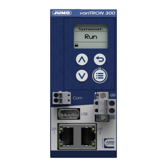
3 Electrical connection (1) Antenna connector (2) Display (3) Control elements (4) Voltage supply DC 24 V (5) Interface LAN2 (6) Interface LAN1 (7) USB host interface (8) RS485 interface (9) Switches for terminating resistors (RS485), inside the housing 3.3.2 Interfaces Connection Designa-... -
Page 30: Voltage Supply
3 Electrical connection 3.3.3 Voltage supply Connection Designa- Num- Symbol and terminal designation tion Voltage supply In +24 V and +24 V 3.3.4 Terminating resistors The terminating resistors of the RS485 interface are deactivated per default. To activate them, switches 1 and 2 must be closed. -
Page 31: Operation
chapter 6 "Startup", Page 95 Device-specific information in this chapter All the information in this chapter that refers to the JUMO variTRON 500 (705002) device also applies in principle to the JUMO variTRON 300 (705003) device. Differences between the devices will be men- tioned at the relevant points if necessary for the use of this manual. -
Page 32: Device
4 Operation Device 4.2.1 Display and control elements (1) Display in basic status (2) Title of display (3) Display of system status or system bus status (4) Display of log-on status or event, e.g. using icons (see table) (5) "Back" key (in menu: back to previous menu level, exit editing mode without making a change) (6) "Menu/OK"... -
Page 33: Device Menu
4 Operation 4.2.2 Device menu To access the device menu from the start screen, press the "Menu/OK" key. The following overview shows the menu levels where individual functions can be configured (by selecting or entering data) or information is shown. The information that is shown on the device display depends on the user's rights. - Page 34 4 Operation Sub-menu 1 Sub-menu 2 Sub-menu 3 Web server HTTP (selection options: Active, Inactive, Redirect to HTTPS) HTTP port number (to be en- tered) HTTPs port number (to be en- tered) System status UI Screensaver Function (selection options: Off, Waiting period (idle time) (to be entered, in milliseconds) chapter 4.4.4 "Configuration", Page 63...
-
Page 35: User Log-On
The SSH password gives the user unrestricted access to the operating system (root privileges). Changes at the operating system level can result in the device functions developed and tested by JUMO being inadmissibly changed. JUMO accepts no liability for this. -
Page 36: Reset To Factory Settings
CAUTION! Reset to default settings All data will be deleted. All settings will be reset to the default settings (JUMO), including the user admin- istration settings (user "Master", password "9200"). Back up the hardware configuration and settings beforehand using the setup program. -
Page 37: Setup Program
4 Operation Setup program 4.3.1 Start page The setup program is used to create new projects and edit existing projects. The "Projects" window contains corresponding buttons. If applicable, the most recently edited and opened projects are also shown. These are likewise provided in the form of buttons for opening the re- spective project or switching to a project that is already open. -
Page 38: Project Map
• Hardware assistant for system bus: Define the hardware configuration for the entire system • Wtrans hardware assistent (only for variTRON 300): Select Wtrans transmitters (wireless transmis- sion of measured values) • Configuration: Configure the device (CPU) and modules and determine their parameters •... -
Page 39: Project Management
4 Operation 4.3.3 Project management Display project information, enter the designation and description of the project, convert the project Parameters/functions: • Filename (non-editable): Project file name, which was automatically assigned when creating the project. • Path (non-editable): Path under which the project file has been saved. •... -
Page 40: System Bus Hw Assistant
(right arrow/downward arrow). Hardware configuration The "Hardware configuration" area shows the device (in this case the variTRON 300 CPU) and, if appli- cable, all previously added system components (modules). The view can be enlarged or reduced using the zoom function ("+"... - Page 41 If the hardware configuration contains router units (router modules), these units must be connected with one another. To do so, proceed as follows (also applies analogously to the connection between the variTRON 300 CPU and the router module): 1. Click on a router module.
-
Page 42: Optional Module (Alias Device Address)
4 Operation 3. Click on a free socket on the other router module (or on the "Close connection" connector icon on the right next to the socket). The connection between the two sockets is established (color change). Please note: To delete the connection, click on the "Delete connection" x icon on the right next to one of the two sockets (or remove a router module) 4. - Page 43 4 Operation Configuration of optional modules When creating a project with the setup program (hardware arrangement), all modules are initially man- datory modules. To form a line with optional modules (HC group), the relevant (upstream) router module must be configured as an optional module: •...
-
Page 44: Wtrans Hw Assistant
4 Operation 4.3.6 Wtrans HW assistant Select Wtrans transmitters (wireless measured value transmission) The window is separated into three areas: • Transmitter configuration • System components • Settings To increase the size of the "Transmitter configuration" area, the "System components" and "Settings" ar- eas can be hidden by clicking the relevant button (right arrow/downward arrow). - Page 45 4 Operation Settings The "Settings" area displays information on the system component that is currently selected and enables certain settings to be configured: • Product group number (non-editable) • Module label: Tag name for the system component (editable; can no longer be changed once the hardware configuration has been applied) •...
-
Page 46: Configuration
• Cloud gateway: Configuration of the connection to JUMO Cloud (as of system version 4) • Wtrans gateway (only for variTRON 300): Settings for using the JUMO Wtrans transmitters (as of system version 5) • Node-RED (as of system version 4): Activation of programming tool Node-RED •... - Page 47 4 Operation chapter 5 "Configuration", Page 69 NOTE! The settings configured under "Bus > Master" influence the transfer of data via the system bus. Sub- optimal settings here will disrupt or even interrupt the communication within the system. For this reason, these parameters are only permitted to be modified by a service engineer from the device manufacturer (or by someone acting on their instructions).
-
Page 48: Plc Application
4 Operation 4.3.8 PLC application Determine the start parameters for the CODESYS PLC programming system, start CODESYS Parameters/functions: • Start to debug: Start CODESYS without a newly created device description (the compilation process is not run again before logon, the program is not stopped when logging on to the target system) •... -
Page 49: Plc Parameter Definition
4 Operation 4.3.9 PLC parameter definition Determine the start parameters for the CPV Editor (CPVE), start the CPVE This function is only available if the CPV Editor has been installed. NOTE! The CPV Editor is used to create customer-specific configuration and process data. The CPV Editor requires specific knowledge and is intended for use by the manufacturer only (service that is subject to a fee). -
Page 50: Languages
4 Operation 4.3.10 Languages Select the project language and device languages, export and import languages (texts), edit languages Language settings Parameters/functions: • Use application language: Use the language of the setup program as the project language • Project language (button; not active if the application language is being used): Select the project lan- guage from the list (drop-down menu) •... - Page 51 4 Operation Project languages Parameters/functions: • List: Project languages which are available for selection as the device language – Language selected (ticked): Language can be selected in the device – "+" button: Add another language to the list of project languages –...
-
Page 52: Data Transfer
4 Operation 4.3.11 Data transfer Establish a connection to a device, data transfer to/from the device, import and export the configuration Connection Parameters/functions: • Current connection (button): Displays the current connection; if necessary, select a different connec- tion from the list •... - Page 53 4 Operation Transfer settings Parameters/functions: • System state after configuration transfer (as of system version 5): – Unchanged: After the transfer, the device returns to the system state it had before the transfer. – STOP: The device remains in the "Stop" system state after transmission. •...
- Page 54 Yes (= red) Only visible values of known parameters (as of system version 4) Wtrans Gateway Yes (= red) Only visible values of known parameters (only for variTRON 300) Node-RED No (= gray) Do not transfer (as of system version 3) Batches...
-
Page 55: Messages
4 Operation 4.3.12 Messages Display and act on project messages Project messages that require user action (acknowledge message, perform further actions if necessary) are displayed here. -
Page 56: Connections
4 Operation 4.3.13 Connections Connection list Configure a connection to a device; overview of all configured connections Parameters/functions: • Designation (editable): Freely selectable designation for the connection • Description (editable): Text for a more detailed description of the connection • Version of most recently connected device: Version number of the device software •... - Page 57 4 Operation If applicable, the old value of the parameter that has just been changed is shown at the bottom of this window. Clicking the "Back" button (circular arrow) after the line containing the changed parameter (above) discards your data entry. Both areas can be hidden by clicking the relevant button (arrow).
-
Page 58: Jumo Web Cockpit
4 Operation JUMO Web Cockpit JUMO Web Cockpit is a web application that enables you to access the device using a web browser. The following web browsers are supported: Mozilla Firefox, Google Chrome, Microsoft Edge, Opera NOTE! JUMO has successfully tested the aforementioned web browsers using Microsoft Windows 10. If you use a different web browser or another operating system, JUMO cannot guarantee that the application will work correctly. - Page 59 • EtherCAT (system bus): Display information on the master and slaves (modules); perform actions • Only for variTRON 300: Wtrans gateway (status of transmitters) • User management: Create users, assign roles • Import configuration: Transfer configuration file (.jcf) to the device •...
- Page 60 4 Operation Selecting the menu item "System bus" accesses the function "Service > System bus" directly. Only for variTRON 300: Selecting the menu item "Wtrans gateway" accesses the function "Service > Wtrans gateway" directly. "User" button Designation Description Master The user name of the logged-on user is displayed here.
-
Page 61: Device Information
Certificate management If applicable, information on certificates is displayed here. PLC runtime environment Information about the PLC runtime system is displayed here. variTRON 300: Retain handling only possible via sync in CODESYS (JUMO library available as of sys- tem version 6). -
Page 62: Events
Cloud gateway Information about the cloud gateway is displayed here (status, version). Wtrans gateway (only for variTRON 300) Information about the Wtrans gateway is displayed here (version, radio frequency; Wtrans transmitters: e.g. transmitter ID, battery status, RSSI value; measured value, transmission interval). -
Page 63: Configuration
4 Operation 4.4.4 Configuration The following sections are merely intended to provide an overview of the functions which are configured under the respective tile. The process of configuring the individual functions in the CPU (master) is described in detail in the "Con- figuration"... - Page 64 The connection to the JUMO Cloud (available as of system version 4) is configured here. Wtrans gateway (only for variTRON 300) Settings for using the JUMO Wtrans transmitters are made here (available as of system version 5). Node-RED Here, the use of the programming tool Node-RED is activated.
-
Page 65: Service
"Initialization". This interrupts the cyclic transmission of values. Use this function for servicing purposes only! Wtrans gateway (only for variTRON 300) Information about the Wtrans transmitters is displayed here (e.g. status, transmitter ID, battery status, RSSI value). - Page 66 Visibility of the user in the CODESYS SystemStatusUi Visibility of the user in the device dis- play (only for variTRON 300 and 500) When assigning this right, take into ac- count the restricted possibilities for dis- playing and entering data on the device display (user name, password).
-
Page 67: File Explorer
4 Operation A user can be edited, and it can also be removed. Likewise, the user's password can also be changed. The "addUser" function is used to create a new user. NOTE! Due to the restricted possibilities for displaying and entering data on the device display, users with the right "SystemStatusUi"... - Page 68 4 Operation The files are available for download in the web browser (click on the file).
-
Page 69: Configuration
As a basic principle, the device can be configured on the device itself, as well as using the setup program or the "JUMO Web Cockpit" web application. However, these configuration options differ in terms of the function areas that can be configured. -
Page 70: Device Manager
5 Configuration Device manager Device settings Parameter Selection/data input Description Device language Select language Language in which the texts are shown on the de- vice display. Texts that do not have a translation in the selected language are displayed in English or German (or, if applicable, in the so-called developer language). -
Page 71: Customer-Specific Linearization
5 Configuration Parameter Selection/data input Description Server 1 Enter the address of the time Up to three time servers can be entered. server (or use an existing ad- Server 2 The server list is processed top down, in other dress) words, the next time server on the list is only que- Server 3 Example: de.pool.ntp.org... - Page 72 5 Configuration Parameter Selection/data input Description -99999 to 99999 (max. up to 20th order) Grid values Customer-specific linearization is specified by entering up to 200 grid points (pairs of values X/Y). The value of X stands for the physical measured value (e.g., voltage in V, current in A, or resistance in ohm; depending on the sensor type) and the value of Y stands for the linearized value (e.g., temperature in °C).
-
Page 73: System Bus
chapter 1.8 "Available technical documentation", Page 18 If used together with a type JUMO variTRON CPU, the description of the NV connecting list provided in the manual does not apply. In this case, all external connections (connections running via the system... -
Page 74: Data Carrier Management
5 Configuration Data carrier management Network drives Here up to 5 network drives are mounted under Linux (available as of system version 7). Parameter Selection/data input Description Name Enter text Designation for the network drive Examples: Drive1, Drive2 Network path Enter text Network path of the drive Examples: //Server/NetDrive, //Server/NetDrive2... -
Page 75: Ethernet
5 Configuration Ethernet LAN1 Parameter Selection/data input Description Method Method for assigning the IP address Manual The IP address must be assigned manually. Automatic The IP address is obtained from a DHCP server. IP address 0.0.0.0 to 255.255.255.255 Manually assigned IP address The IP address may need to be requested from the administrator in question. -
Page 76: Email
5 Configuration Email Parameter Selection/data input Description SMTP server Enter address Address (URL) of the email server for SMTP (smtp.example.de) Port 0 to 65535 Port number of the email server for SMTP (25) The port number is dependent on the email provid- er and the type of encryption (usually: TLS = 465, StartTLS = 587). -
Page 77: Plc Configuration
5 Configuration PLC configuration 5.8.1 Units These settings are relevant for the automatic conversion performed when the temperature unit is changed (°C/°F) (relates only to the PLC application). Parameter Selection/data input Description Setting for abso- Unit for temperature value lute temperature °C Deg. - Page 78 5 Configuration Parameter Selection/data input Description Power off Behavior of the program generator when the pow- er failure is over. Abort The program is aborted; the program generator enters basic status. Continuation The program continues running from the point that it was at when the power failed.
- Page 79 5 Configuration Tolerance band monitoring Parameter Selection/data input Description Alarm type Inactive The tolerance band monitoring is not active. Event The tolerance band violation is entered as an event in the event list. Alarm The tolerance band violation is entered as an alarm in the event list and the alarm list.
- Page 80 5 Configuration Parameter Selection/data input Description Upper tolerance band limit (tol. band upper limit) Minimum -99999 to 99999 Admissible minimum value for the upper tolerance band limit Maximum -99999 to 99999 Admissible maximum value for the upper tolerance band limit Setpoint value 01 to Setpoint value 30 Designation Enter text (or use existing text) Designation of the setpoint value...
-
Page 81: Analog Variables
5 Configuration Setting of setpoint values: setpoint value units Parameter Selection/data input Description Setpoint value 01 Unit of the setpoint value concerned unit to No unit Setpoint value 30 Absolute temperature Temperature value unit Relative temperature Temperature difference Relative humidity Relative humidity Ratio Ratio of two values A and B (A / B) in percent... -
Page 82: Programs
5 Configuration 5.10 Programs Each program (each program plan) can consist of a maximum of 200 program sections. Up to 30 setpoint values and up to 32 operating contacts can be used in each program section. Tolerance band monitoring can be set up for the first setpoint value. This means that the relevant actual value is monitored;... - Page 83 5 Configuration Program channel Parameter Selection/data input Description Number of sec- 0 to 200 Number of program sections that the program gen- tions erator is to process. Program section 1 to Program section 200 Process step 0 to 200 The process step specifies the limits of the section (procedural step) time and defines which setpoint values are avail- able.
-
Page 84: System Status Ui
5 Configuration 5.11 System status UI This function area relates to the configuration of the device display. Screensaver Parameter Selection/data input Description Function Activate screen switch-off The function is inactive. The screen is switched off once the waiting period has elapsed. Waiting period (s) 10 to 3600 Waiting period in seconds... -
Page 85: Real-Time Processing
The process values are only temporarily stored in the central processing unit to bridge network failures before these values are transferred to the Datastore for storage. The Datastore is part of the JUMO smartWARE Evaluation software. A visualization using only the central processing unit is not possible. - Page 86 5 Configuration Parameter Selection/data input Description End of display -99999 to 99999 (100) Upper limit of display range range As of system version 7: -1.7e+307 to 1.7e+307 Unit Select unit Value unit (only with system (No unit) As of system version 7, the unit of the input signal version 6) is used.
- Page 87 5 Configuration Parameter Selection/data input Description Post-trigger time 0 to 10 (0) Extends event operation after the control signal has been deactivated. Memory rate 00:00:01 to 24:00:00 Recording interval [hh:mm:ss] (00:00:01) Time interval at which the values of the analog and digital signals of the group are stored for evalua- tion.
-
Page 88: Datastore Gateway
Here the connection to the database (Datastore) is configured and activated (available as of system ver- sion 6). In the Datastore, the recorded process data is stored. The data is then available for evaluation with JUMO smartWARE Evaluation (as of system version 6). Parameter... -
Page 89: Cloud Gateway
5 Configuration 5.14 Cloud gateway Here the connection to the JUMO Cloud is configured (available as of system version 4). Before this, the device must be configured as a data source in the JUMO Cloud. Parameter Selection/data input Description Connection to the... -
Page 90: Wtrans Gateway
5 Configuration 5.15 Wtrans gateway Settings for using the JUMO Wtrans transmitters are made here (available as of system version 5). General Parameter Selection/data input Description Radio frequency Wtrans radio frequency (MHz) 868.4 Europe 912.6 to 917.4 America, Australia, Canada and New Zealand... -
Page 91: Node-Red
5 Configuration 5.16 Node-RED The Node-RED graphical programming tool is present by default, but must be activated before use. Parameter Selection/data input Description Graphical pro- Activation of Node-RED in the central processing gramming tool unit Node-RED Inactive Node-RED is not active. Active Node-RED is active and can be used with a web browser. -
Page 92: Batches
NOTE! With the variTRON 300, the user must ensure that the maximum number of 10 batches is not exceeded. If the maximum number of batches is exceeded during configuration, this will result in the batch in ques- tion not being recorded. - Page 93 5 Configuration Parameter Selection/data input Description Contents of right Text or text source for the right line of the batch re- column port Empty No text Default text Text from the "Default text" parameter Batch name The batch name is used (see "General" section). Batch number The batch number is used together with the text from "Default text".
- Page 94 5 Configuration...
-
Page 95: Startup
Add DIN rail and place router module 1-port (705043) or router module 3-port (705042) as the first module on the DIN rail. Since the variTRON 300 CPU does not have any lateral connections for power supply and sys- tem bus, a router module is required (primary: router module 1 port) to connect further modules. - Page 96 6 Startup d) Check the status LED of all modules. The LED will light up steady green as soon as the system bus has the status "Operational". 7. Configure the modules: Setup program > Project > Configuration > Bus a) Configure the digital and analog inputs and outputs. b) If necessary, configure the controller function of the controller module (incl.
- Page 97 NOTE! Certain changes made to the configuration (e.g., changes to the hardware configuration) will cause the CPU to restart. Further information The JUMO Help Center provides further information, especially on the following topics: • JUMO Cloud • JUMO smartWARE SCADA •...
- Page 98 6 Startup...
-
Page 99: Annex
- Modbus TCP master/slave - PROFINET IO device - EtherCAT slave - OPC UA client - BACnet/IP server/client - JUMO system bus via JUMO variTRON router modules (LAN2 only) Transfer rate 10 Mbit/s, 100 Mbit/s Connecting cable Network cable, at least CAT5 (S/FTP) - Page 100 The RSSI value is an indicator of the strength of the received signal (theoretical value range: -120 to 0). Application Receiver for JUMO Wtrans transmitters (wireless transmission of measured values) Compatible transmitters Wtrans T (902930), Wtrans B (707060), Wtrans p (402060),...
-
Page 101: Display
7 Annex 7.1.2 Display Type LCD, monochrome Resolution 96 × 64 pixels (8 rows) 7.1.3 Electrical data Voltage supply (terminals +24 V and GND) Symbol (see nameplate) Connection At the front (removable terminal strip, 2-pole with PUSH IN technolo- Voltage DC 24 V +25/-20 % SELV Residual ripple Current consumption... -
Page 102: Housing And Environmental Conditions
7 Annex 7.1.4 Housing and environmental conditions Case type Plastic case for DIN rail mounting in the control cabinet (indoor use); DIN rail acc. to DIN EN 60715, 35 mm × 7.5 mm × 1 mm Dimensions (W × H × D) 45 mm ×... -
Page 103: Buffer Battery Replacement
7 Annex Buffer battery replacement CAUTION! The device contains a buffer battery that is used for data buffering when the device is in switched off mode or if the power fails. The operating life of the battery is typically 6 years. If the battery is low, this is indicated by a fault message in the event list ("Battery almost empty"). - Page 104 7 Annex Opening the housing 1. If necessary for space reasons, remove the central processing unit from the DIN rail. To do this, please follow the instructions on dismounting previously provided in this document. 2. Loosen both locking hooks (A) one after the other using a screwdriver. To do this, insert the screw- driver into the small slot (B) below the locking hook and turn carefully (maximum 90°).
- Page 105 7 Annex Replacing the battery 1. Remove the old battery (C) from the holder and replace it with a new one of the same type (button cell CR2032). Closing the housing 1. Insert the front housing section into the rear housing section and ensure that both locking hooks en- gage.
-
Page 106: Led Displays
7 Annex LED displays The "S" LED (Status) indicates the status of the relevant module (prerequisite: "P" LED lights up). Display modes The following table lists all possible states of the "S" LED (module-dependent). Display mode Description Green sym- Red symbol LED state not relevant LED off LED on (permanently lit) - Page 107 7 Annex System states and errors The following table lists all the system states and errors that are indicated by the "S" LED (module-de- pendent). Category "S" LED Meaning Diagnos- Recommended action (Status) tics with Start error Module error (hardware does not Replace module start up) Start error...
-
Page 108: Open-Source Software
Insofar as the respectively applicable license terms justify a claim on the provision of source codes or other information, JUMO GmbH & Co. KG will provide the source code and the license texts on a con- ventional data carrier at the cost incurred by creating the data carrier. -
Page 109: China Rohs
7 Annex China RoHS... - Page 110 7 Annex...
- Page 112 JUMO GmbH & Co. KG JUMO Instrument Co. Ltd. JUMO Process Control, Inc. Street address: JUMO House 6724 Joy Road Moritz-Juchheim-Straße 1 Temple Bank, Riverway East Syracuse, NY 13057, USA 36039 Fulda, Germany Harlow, Essex, CM20 2DY, UK Delivery address:...
Need help?
Do you have a question about the variTRON 300 and is the answer not in the manual?
Questions and answers