JUMO mTRON T Manual
Measuring,control, and automation system
Hide thumbs
Also See for mTRON T:
- Operating manual (278 pages) ,
- System description (74 pages) ,
- Installation instructions manual (38 pages)

Related Manuals for JUMO mTRON T


Summary of Contents for JUMO mTRON T
- Page 1 JUMO mTRON T Measuring, Control, and Automation System Central Processing Unit Interface Description Modbus 70500100T92Z001K000 V2.00/EN/00575586...
-
Page 3: Table Of Contents
Contents Introduction ............5 Available technical documentation . - Page 4 Contents Examples for the data transmission options with frames ......75 Modbus address tables .
-
Page 5: Introduction
1 Introduction Available technical documentation The documents specified below are available for the measuring, control, and automation sys- tem (previous document number in parentheses). 1.1.1 General information Product Type of documentation Printed PDF file Measuring, Data sheet 70500000T10... control, and System manual 70500000T90... - Page 6 1 Introduction 1.1.3 Input/output modules Product Type of documentation Printed PDF file Multichannel Data sheet 70501000T10... controller module Operating manual 70501000T90... (B 705010.0) Installation instructions 70501000T94... (B 705010.4) Relay module Data sheet 70501500T10... 4-channel Operating manual 70501500T90... (B 705015.0) Installation instructions 70501500T94...
- Page 7 1 Introduction 1.1.5 Operating, visualization, recording Product Type of documentation Printed PDF file Multifunction Data sheet 70506000T10... panel 840 Operating manual 70506000T90... (B 705060.0) Modbus interface description 70506000T92... (B 705060.2.0) Installation instructions 70506000T94... (B 705060.4) Operating panels Data sheet 70506500T10... 1.1.6 Power supply units Product...
-
Page 8: Content Of The Technical Documentation
1 Introduction Content of the technical documentation The documentation for the measuring, control, and automation system is intended for plant manufacturers and users with specialist training. It has a modular structure and comprises dif- ferent sections. In the following subsections, the various types of documents are listed (previous document number in parentheses). - Page 9 1 Introduction 7050XX00T90... (B 7050XX.0) Operating manual The operating manuals of the individual modules contain all information on installation, electri- cal connection, startup, operation, and – if required – parameterization and configuration. 7050XX0XT92... (B 7050XX.2.X) Interface description The interface description provides information about the use of that interface and on commu- nication with other devices, superordinate systems or certain sensors.
- Page 10 Download procedure: Step Action On the JUMO website, enter the number of the relevant product group in the search field at the top right (e.g. 705001 for the central processing unit) and start the search. The search results are listed.
-
Page 11: Safety Information
1 Introduction Safety information 1.3.1 Warning symbols DANGER! This symbol indicates that personal injury caused by electrical shock may occur if the re- spective precautionary measures are not carried out. WARNING! This symbol in connection with the signal word indicates that personal injury may occur if the respective precautionary measures are not carried out. - Page 12 1 Introduction...
-
Page 13: Connecting Interfaces
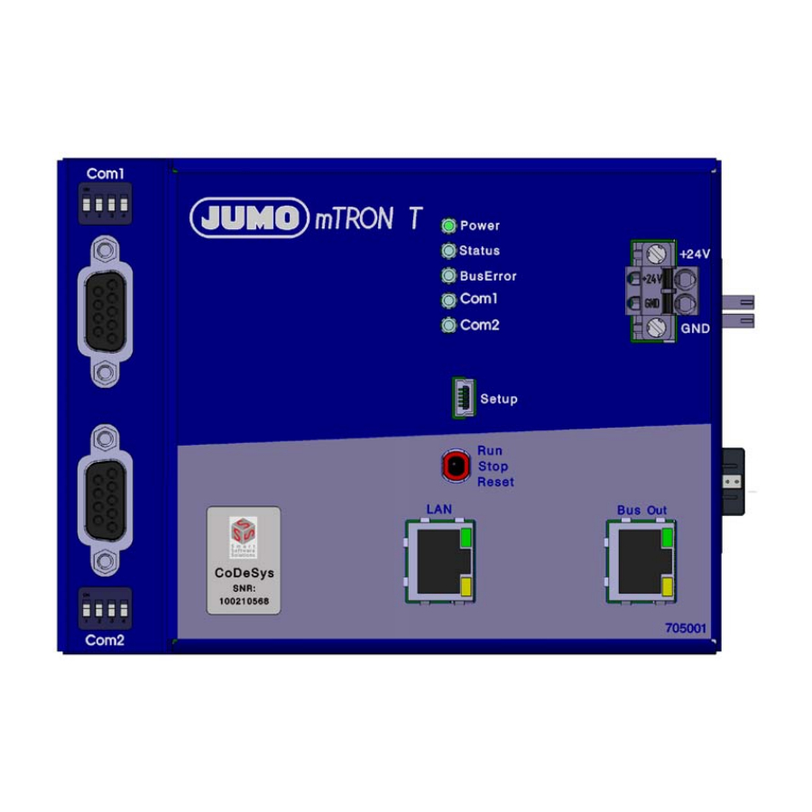
2 Connecting interfaces Position of the interfaces The central processing unit is equipped with a standard LAN interface. It is designed to transmit data using the HTTP protocol (e.g. PC with setup program or Web browser) or the Modbus pro- tocol (Modbus/TCP, master or slave). -
Page 14: Interface Assignment
2 Connecting interfaces Interface assignment Connection Designation Connection element Ethernet 1 TX+ Transmission data + 2 TX- Transmission data - 3 RX+ Received data + 6 RX- Received data - Serial inter- Com1, 2 RxD Received data face Com2 3 TxD Transmission data (RS232) 5 GND... - Page 15 2 Connecting interfaces 2.2.1 Terminating resistors The internal terminating resistors for the Com1 and Com2 interfaces are only relevant for RS422/485. The terminating resistors are deactivated by default. To activate them, DIP switches 1 to 4 for the relevant interface must be pushed upward using a suitable tool such as a ballpoint pen (ON position).
-
Page 16: Serial Interface
2 Connecting interfaces Serial interface Setup dialog Parameters Parameter Selection/settings Description Protocol Modbus slave Modbus RTU (central processing unit as Modbus slave) The device address is assigned dynami- cally during hardware configuration. Modbus master Modbus RTU (central processing unit as Modbus master) Baud rate Baud rate with which the interface is operated. - Page 17 2 Connecting interfaces Parameter Selection/settings Description Modem active Not selected (empty) No modem operation (Modbus slave is connected directly to serial bus). Selected (checkmark) Modem operation (Modbus slave is con- nected to the Modbus master via the modem). Additional settings are required here ("Modem"...
- Page 18 2 Connecting interfaces Parameter Selection/settings Description Call string ATDT AT command for establishing a connec- tion via the modem (ASCII; max. 24 characters) ATDT = selection with dial tone (DTMF) Hang-up string AT command for disconnection via the modem (ASCII; max. 16 characters) ATH (or ATH0) = hang up Alarm message Alarm type...
- Page 19 2 Connecting interfaces Parameters Parameter Selection/settings Description Initialization AT Q0 S95=249 L1 M1 S7=60 S30=9 AT command for modem changeover \N3 ? This default initialization string switches (ASCII; max. 50 characters) the modem to the mode for connecting to the Internet (e-mail server). Phone no.
- Page 20 2 Connecting interfaces Connecting a PC/Notebook with 25-pin Sub-D socket to Com1/Com2 (2) RxD T x D (3) TxD R x D R T S C T S (5) GND Com1/Com2 PC/Notebook...
-
Page 21: Ethernet Interface
2 Connecting interfaces Ethernet interface General information To use the Ethernet interface, a patch/crossover cable is required that is equipped with a RJ45 plug. The Ethernet interface is configured in the setup software. Required parameters, such as DHCP functionality, IP address, sub-net mask, gateway ad- dress, DNS device name, DNS server, and transfer rate, can be configured in the setup pro- gram under P >... -
Page 22: Ethernet Settings For Modbus/Tcp
2 Connecting interfaces Ethernet settings for Modbus/TCP This menu is used to implement settings for the Modbus/TCP operating mode. If the central processing unit is operating as a Modbus master, it can communicate with up to four external devices (Modbus slaves; device 1 to 4). If it is operating as a Modbus slave, two external de- vices (Modbus master) can simultaneously access the central processing unit. - Page 23 2 Connecting interfaces NOTE! The transfer times in an Ethernet network depend in part on the network architecture and the capacity utilization. This may result in delays during updates of process values.
- Page 24 2 Connecting interfaces...
-
Page 25: Modbus Protocol Description
3 Modbus protocol description Master/slave principle Communication between a master (e.g. PC, notebook or central processing unit) and a slave device (e.g. measuring and control system) and a Modbus takes place according to the master- slave principle, in the form of data request/instruction - response. Master Slave 1 Slave 2... -
Page 26: Temporal Sequence Of Communication
3 Modbus protocol description Temporal sequence of communication Character transmission time The character transmission time (time taken to transmit one character with 8 data bits) depends on the baud rate and the number of bits of the character (see table for data format): Character transmission time [ms] = 1000 ×... -
Page 27: Structure Of A Modbus Telegram
3 Modbus protocol description NOTE! A minimum response time can be configured in the central processing unit using the setup program under CPU > C > S . This preset time is the ONFIGURATION LEVEL ERIAL INTERFACE minimum waiting time before an answer is transmitted (0 to 500 ms). If a smaller value is set, then the response time may be longer than the preset value (internal processing takes lon- ger), the central processing unit responds as soon as internal processing is completed. -
Page 28: Device Address
3 Modbus protocol description Device address The device address can be set between 1 and 254 . It is assigned for the central pro- cessing unit and each module in the setup program under P > P > H ROJECT NAME ROJECT . - Page 29 3 Modbus protocol description Important information on the bit commands To use bit commands correctly and evaluate the results correctly, it is important to understand the order in which the data words and the bits they contain are arranged. The Modbus standard specifies that when reading out word by word the most significant byte (msb) is specified first.
- Page 30 3 Modbus protocol description 3.6.1 Read n bit This function is used to read n bits starting from a specific address. Data request Slave address Function Address Number of bit Checksum 0x01 or 0x02 of first bit 1 byte 1 byte 2 bytes 2 bytes 2 bytes...
- Page 31 3 Modbus protocol description Data request: 00 31 00 02 ED 80 Slave Function Response: D1 79 Slave Function Bytes Bit value The value of the read out bits is 02 (= 2 = 10 ): bit 0 = 0 and bit 1 = 1 NOTE! If the bits are not to be read out of a 32-bit field, but rather from a 16-bit field, it is not neces- sary to add 10...
- Page 32 3 Modbus protocol description ue is reached. The least significant bit (lsb) in each word is also transmitted first here. This ex- ample yields the following arrangement: Bit 48 to bit 53 Bit 32 to bit 47 Bit 16 to bit 31 Bit 0 to bit 15 Highest value Lowest value...
- Page 33 3 Modbus protocol description 3.6.2 Reading n words This function is used to read n words starting from a specific address. Data request Slave address Function Address Number of words Checksum CRC 0x03 or 0x04 of first word 1 byte 1 byte 2 bytes 2 bytes...
- Page 34 3 Modbus protocol description 3.6.3 Write one bit In the write bit function, the data blocks for the instruction and response are identical. Instruction Slave address Function Bit address Bit value Checksum CRC 0x05 1 byte 1 byte 2 bytes 2 bytes 2 bytes Bit value xx = 00: bit is set to 0...
- Page 35 3 Modbus protocol description 3.6.4 Write one word In the write word function, the data blocks for the instruction and response are identical. Instruction Slave address Function Word address Word value Checksum CRC 0x06 1 byte 1 byte 2 bytes 2 bytes 2 bytes Response...
- Page 36 3 Modbus protocol description 3.6.5 Write n words Instruction Slave address Function Address of Number of Number of Word Checksum 0x10 first word words bytes value(s) 1 byte 1 byte 2 bytes 2 bytes 1 byte x bytes 2 bytes Response Slave address Function...
-
Page 37: Transmission Formats (Integer, Float, Double, And Text Values)
3 Modbus protocol description Transmission formats (integer, float, double, and text val- ues) Function 0x03 or 0x04 (reading n words) is used to read out integer, float, double, and text val- ues. Data request Slave address Function Address Number of words Checksum CRC 0x03 or 0x04 of first word... - Page 38 3 Modbus protocol description 3.7.2 Float values For float values, Modbus operates with the IEEE 754 standard format (32 bit), but with the dif- ference that byte 1 and 2 are changed over with byte 3 and 4. Single-float format (32 bit) according to standard IEEE 754 SEEEEEEE EMMMMMMM MMMMMMMM...
- Page 39 3 Modbus protocol description NOTE! The order of the bytes depends on how the float values are saved in the respective applica- tion. The bytes may have to be changed over in the interface program accordingly. 3.7.3 Double values For double values, Modbus also operated with the IEE 754 standard format (32 bit). Unlike float values, bytes are not changed over for double values.
- Page 40 3 Modbus protocol description Example In this example, the value of analog variable 1 is to be read out at address 0x1071 of the central processing unit. The value here is to be 1234567.89 (0x4132D687E3D70A3D in the IEEE 754 format). Data request: 10 71 00 04...
-
Page 41: Checksum (Crc16)
3 Modbus protocol description Checksum (CRC16) Calculation scheme The checksum (CRC16) is used to detect transfer errors. If an error is identified during evalu- ation, the device concerned does not respond. CRC = 0xFFFF CRC = CRC XOR BytesOfMessage For (1 to 8) CRC = SHR(CRC) if (shifted to the right flag = 1 then... -
Page 42: Error Messages
3 Modbus protocol description Error messages 3.9.1 Modbus error codes The slave device does not respond The slave will not respond in the following cases: • The baud rate and/or data format of the master and slave do not match. •... - Page 43 3 Modbus protocol description 3.9.2 Error messages for invalid values For measured values in the float format, the error number appears directly in the value, i.e. it contains the error number instead of the measured value. Error code with Errors float values 1.0 ×...
- Page 44 3 Modbus protocol description 3.9.3 Error codes as integer return values For some longer sequences (e.g. e-mail dispatch or active transmission of frames as a Modbus master), an error code is entered at the end in an event field or event list. Error codes Error code Description...
- Page 45 3 Modbus protocol description Error code Description Edit is inadmissible when the program is active Copy is inadmissible when the program is active MANUAL is inadmissible during AUTO lead time Segment change Image update required No DB number, image update by PLC No DB number for process values of PLC Printer loaded or not operational Setpoint value 1 was not programmed...
- Page 46 3 Modbus protocol description Error code Description Message pool cannot be generated Memory from message pool cannot be inquired Message cannot be transmitted Error list: processing MQX functions Task creation failed Hardware-Timer not created Error list: flash processing Data flash write error Error list: other errors Undefined error Division by zero...
- Page 47 3 Modbus protocol description Error code Description Unexpected BUSY from the modem Unknown authentication protocol Ignored LCP option Unexpected DELAYED from the modem Unexpected NODIALTONE Unknown PPP protocol Unknown PAP code Ignored IPCP option Ignored IPCP code Unknown CHAP code IP checksum incorrect Unknown IP protocol Unknown ICMP type...
- Page 48 3 Modbus protocol description Error code Description TCP socket is already closed Incorrect frame configuration Error list: file system processing Error when installing the partition manager Error when installing the MFS file system Error when deinstalling the partition manager Error when deinstalling the MFS file system...
-
Page 49: Serial Transmission Modes
4 Serial transmission modes Modbus master operation via serial interface Interface parameters frame configuration RS232/ RS485 Modbus 8 read slave Driver frames (base unit) 8 write Modbus frames slave If the central processing unit has been configured as a master, it can send requests on the bus to slaves. - Page 50 4 Serial transmission modes Chronological sequence The respective interface searches for all frames configured for it (setup program: CPU > S ETUP > M > menu item I ) and cyclically transmits ONLY ODBUS FRAMES FOR READING WRITING NTERFACE them in sequence to frame 1, frame 2, and frame 3 as displayed below. Frame 1 Frame 2 Frame 3...
-
Page 51: Modbus Slave Operation Via Serial Interface
4 Serial transmission modes Modbus slave operation via serial interface Interface parameters + Modem parameters (if applicable) + E-mail parameters (if applicable) SystemIO data RS232/ RS485 Config. Driver parameters (base unit) Modem (if applicable) Alarm message If the central processing unit has been configured as a slave, it responds to Modbus requests from the master in the network. -
Page 52: Plc Access To The Serial Interface
4 Serial transmission modes PLC access to the serial interface 4.3.1 Activation The PLC can access the serial interface(s). To do this, the ComSetSettings() initialization func- tion must be used. Once the PLC has programmed its parameters using ComSetSettings(), a new protocol ("PLC- controlled") is activated. - Page 53 4 Serial transmission modes 4.3.3 End identifier conditions The 3S definitions contain all the necessary end identifier conditions, which are required for building a package when receiving individual characters: • Length in bytes is transmitted as parameter uiSize for ComRead() = max.
- Page 54 4 Serial transmission modes PLC as a slave A slave continuously waits for reception and only transmits if it is requested to do so by the mas- ter. The parameters for the end identifier conditions must be set as follows: possibly: length = x bytes response time-out = 0 ms (endless) possibly: character time-out T2 = y ms...
-
Page 55: Rs232 And Rs422/485
4 Serial transmission modes RS232 and RS422/485 The serial interface is implemented using two different additional cards for the central process- ing unit. The type of the used interface board, RS232 or RS422/485, is automatically detected by the central processing unit via the hardware ID. In Modbus slave operation, these interfaces can be used to connect visualization software and also for Modem connections. - Page 56 4 Serial transmission modes...
-
Page 57: Ethernet Transmission Modes
5 Ethernet transmission modes Modbus/TCP Modbus/TCP uses Ethernet as a transmission standard. Two transmission options can be used here: • Modbus/TCP slave for transmitting individual values • Modbus/TCP master for transmitting entire data frames The advantage of using Modbus/TCP and the Ethernet interface is in the high speed and the company-wide availability of the connected devices. - Page 58 5 Ethernet transmission modes Example: reading n words Read the IP address of the central processing unit. Here in the example, it is the address 10.10.1.69. Since each IP address range is stored in a word, 4 words (8 bytes) must be read out.
-
Page 59: Networking With Modbus/Tcp
5 Ethernet transmission modes Networking with Modbus/TCP The image below provides an overview on the networking options when using the Modbus/TCP protocol: Ethernet Frame Modbus/TCP master Modbus/TCP slave Modbus/TCP slave IP = x.x.x.x IP = x.x.x.y IP = x.x.x.z (e.g. central process. unit) (e.g. -
Page 60: Modbus Slave With Modbus/Tcp
5 Ethernet transmission modes Chronological sequence The respective interface searches for all frames configured for it (setup program: CPU > S ETUP > M > menu item I ) and cyclically transmits ONLY ODBUS FRAMES FOR READING WRITING NTERFACE them in sequence to frame 1, frame 2, and frame 3 as displayed in the image below. Frame 1 Frame 2 Frame 3... -
Page 61: Browser Connection And Web Server
5 Ethernet transmission modes Browser connection and Web server The central processing unit can also be accessed by a browser using the HTTP protocol. The required URL for this is the IP address of the central processing unit (in the above example 10.13.6.177). -
Page 62: E-Mail (Smtp And Pop3)
5 Ethernet transmission modes E-mail (SMTP and POP3) The central processing unit can send e-mails (e.g. alarms). In this case, it is the master (client) and can access SMTP servers at the standard port (25) as well as POP3 servers at the stan- dard port (110) Setup PC IP=x.x.x.x... - Page 63 5 Ethernet transmission modes serves as a gateway between the local company network and the worldwide Internet. It is also used for the conversion of "local" IP addresses (used in the company network) to "once-only" IP addresses (used in the Internet). The device software cannot address a proxy! However, there are also "transpar- ent proxies"...
- Page 64 5 Ethernet transmission modes NOTE! Information on configuring the e-mail functionality can be found in the central processing unit's operating manual B 705001.0. Transmitting an e-mail via the Internet Here, several steps depend on configured device parameters. An error code of the event entry (particularly the error codes 120 to 174) can suggest an incorrectly set parameter.
- Page 65 5 Ethernet transmission modes Conditions fulfilled to send an e-mail? Loading of current own IP address Configuration: Authentification = SMTP-After-POP Request to DNS server to get POP3 server name TCP connection to POP3 server Login to mail account with user name + password TCP connection is closed (w/o reading of an e-mail) Request to DNS-Server...
- Page 66 5 Ethernet transmission modes...
-
Page 67: User Frames
6 User frames General information The central processing unit allows the user to individually compile Modbus frames for his ap- plication. This achieves a high level of flexibility and the user can thus reduce the data ex- changed on the bus to the volume he requires. This provides a significant advantage with regard to the transmission speed. - Page 68 6 User frames NOTE! When transmitting as a Modbus master, repetitive errors are entered in the event list. Corre- sponding error codes can be found in chapter 3.9.3 "Error codes as integer return values". Error monitoring Each frame is monitored for data transmission. If an error occurs, the corresponding error flag is set, an error code is also saved for each frame and an entry is written in the event list.
-
Page 69: Compiling Modbus Frames
6 User frames Compiling Modbus frames The "Modbus frames for reading" and "Modbus frames for writing" options are found under S > CPU > S in the setup program. UP NAME ETUP ONLY 6.3.1 Modbus frames for reading This function is used to compile up to eight Modbus frames for reading process values of ex- ternal devices (via interface) individually for each opposite side. - Page 70 6 User frames Parameter Selection/settings Description Interface The selection determines whether the frame is actively transmitted as a master or only available for requests as a slave. In case of a Modbus master, the interface on which the relevant frame is used is also specified. If it is a LAN interface, the exter- nal device to be addressed must also be selected.
- Page 71 6 User frames Editing To open this window, use the "Edit" button: Parameter Parameter Selection/settings Description Variables Analog, digital, integer, and text variables Inactive No variable selected Select variable Selector for selecting a variable Data type The data type depends on the type of the external input preset in the setup pro- gram.
- Page 72 6 User frames Parameter Selection/settings Description Factor Using the factor makes it possible to transmit floating point values in the integer format. The transmitter multiplies the data with the corresponding factor before transmission. The data mut be divided by the same value in the receiver. Complete float range allowed, default This factor is used to rescale values dur- value = 1.0...
- Page 73 6 User frames Parameter Selection/settings Description Interface The selection determines whether the frame is actively transmitted as a master or only available for requests as a slave. In case of a Modbus master, the interface on which the relevant frame is used is also specified. If it is a LAN interface, the exter- nal device to be addressed must also be selected.
- Page 74 6 User frames Editing To open this window, use the "Edit" button: Parameter Parameter Selection/settings Description Process value Analog, integer, and digital signals and texts of the input/output modules and the central processing unit (incl. variables and PLC) Inactive No module selected Select module (process value source) The process value of the relevant mod- ule can be selected from a list in the fol-...
-
Page 75: Examples For The Data Transmission Options With Frames
6 User frames Parameter Selection/settings Description Factor Using the factor makes it possible to transmit floating point values in the integer format. The transmitter multiplies the data with the corresponding factor before transmission. The data must be divided by the same value in the receiver. Complete float range allowed, default This factor is used to rescale values dur- value = 1.0... - Page 76 6 User frames...
-
Page 77: Modbus Address Tables
7 Modbus address tables NOTE! These tables are important for external devices that access the central processing unit as a Modbus master (configured as a Modbus slave). Alternatively, external devices can also ac- cess the cenral processing unit using the Modbus frames. Data types and access types Data types Bit x... - Page 78 7 Modbus address tables Address Data type/ Access Signal designation bit number Hex. Dec. 0x00C3 Uint32 Modbus master TCP device 3: actual cycle time in 5 ms ticks 0x00D6 Uint32 Modbus master TCP device 4: actual cycle time in 5 ms ticks 0x00EC Uint32 Com1: for Modbus master: actual cycle time in 5 ms ticks...
- Page 79 7 Modbus address tables Address Data type/ Access Signal designation bit number Hex. Dec. 0x12F1 4849 Boolean Alarm 1 integer variable 1 0x12F2 4850 Boolean Alarm 1 integer variable 2 0x... Boolean Alarm 1 integer variable ... 0x1330 4912 Boolean Alarm 1 integer variable 64 0x1331 4913...
- Page 80 7 Modbus address tables Address Data type/ Access Signal designation bit number Hex. Dec. 0x1637 5687 Uint32 Start program no. x program generator 1 0x1639 5689 Uint32 Start program no. x program generator 2 0x... Uint32 Start program no. x program generator ... 0x1647 5703 Uint32...
- Page 81 7 Modbus address tables NOTE! As of system version 04, 90 external batch texts can be transmitted via Modbus. The texts 1 to 27 remain at the previous Modbus addresses. In addition, all 90 texts, including the texts 1 to 27, are transmitted in a separate address space. For the texts 1 to 27 it must be ensured in the application that only one of the two possible addresses is used.
- Page 82 7 Modbus address tables Address Data type/ Access Signal designation bit number Dec. Bit 2 System collective alarm Bit 3 System collective alarm with acknowledgement Bit 4 System fault Bit 5 System fault with acknowledgement Bit 6 Base unit (central processing unit) collective alarm Bit 7 "Run"...
- Page 83 7 Modbus address tables Address Data type/ Access Signal designation bit number Hex. Dec. 0x16D3 5843 Float Block 1 of analog output 10 (channel 3 SP 2) 0x16D5 5845 Float Block 1 of analog output 11 (channel 3 SP 3) 0x16D7 5847 Float...
- Page 84 7 Modbus address tables Address Data type/ Access Signal designation bit number Hex. Dec. 0x1781 6017 Float Block 7 of analog output 1; see name of block 1 provided by fac- tory 0x1783 6019 Float Block 7 of analog output 2 0x...
- Page 85 7 Modbus address tables Address Data type/ Access Signal designation bit number Hex. Dec. 0x1861 6241 Float Block 14 of analog output 1 0x1863 6243 Float Block 14 of analog output 2 0x... Float Block 14 of analog output ... 0x187F 6271 Float...
- Page 86 7 Modbus address tables PLC integer outputs The meaning of PLC integer outputs (12 blocks each with 24 outputs) is determined by the PLC program. They are named in the setup program under CPU > S > I ETUP ONLY NTEGER PUT TEXTS PLC process values (name provided at the factory in brackets)
- Page 87 7 Modbus address tables Address Data type/ Access Signal designation bit number Hex. Dec. 0x192F 6447 Int32 Block 1 of integer 24 = program channel 3: remaining section time 0x1931 6449 Int32 Block 2 of integer 1 = diverse program data 0x1933 6451 Int32...
- Page 88 7 Modbus address tables Address Data type/ Access Signal designation bit number Hex. Dec. 0x1A81 6785 Int32 Block 9 of integer 1 = diverse program data 0x1A83 6787 Int32 Block 9 of integer 2 0x... Int32 Block 9 of integer ... 0x1AAF 6831 Int32...
- Page 89 7 Modbus address tables PLC digital outputs The meaning of PLC digital outputs (18 blocks each with 32 outputs) is determined by the PLC program. They are named in the setup program under CPU > S > D ETUP ONLY IGITAL PUT TEXTS PLC digital outputs (name provided at factory)
- Page 90 7 Modbus address tables Address Data type/ Access Signal designation bit number Hex. Dec. 0x1B43 6979 Bit field 32 Block 2 digital outputs; intended for program generator 2 0x1B45 6981 Bit field 32 Block 3 digital outputs; intended for program generator 3 0x1B47 6983 Bit field 32...
- Page 91 7 Modbus address tables PLC program texts for program channels 1 to 3 Address Data type/ Access Signal designation bit number Hex. Dec. 0x1CB2 7346 char[73] Text for program channel 1 for generator 1 (= Unicode) 0x1CD7 7383 char[73] Text for program channel 1 for generator 2 (= Unicode) 0x...
- Page 92 7 Modbus address tables PLC limit value 1 and 2 for alarms of the integer variables 1 to 64 Address Data type/ Access Signal designation bit number Hex. Dec. 0x2236 8758 Int32 Limit value 1 for alarm of integer variable 1 0x2238 8760 Int32...
- Page 93 7 Modbus address tables Compiled reading frames Address Data type/ Access Signal designation bit number Hex. Dec. 0x8000 32768 Byte[254] Read frame 1 0x8080 32896 Byte[254] Read frame 2 0x8100 33024 Byte[254] Read frame 3 0x8180 33152 Byte[254] Read frame 4 0x8200 33280 Byte[254]...
-
Page 94: Modbus Addresses Of Other Modules
7 Modbus address tables Modbus addresses of other modules If the central processing unit detects other modules, they can be accessed using the following addresses depending on the module type. The additional modules are available for configuration under virtual Modbus device addresses (1 to 254) as with the setup program under P >... - Page 95 7 Modbus address tables 7.3.2 Modbus addresses for each multichannel controller module NOTE! Signals with labels "NV_..." are intended for the function that corresponds to the respective default names. However, the function ultimately depends on how the signals are used in the configuration.
- Page 96 7 Modbus address tables Address Data type/ Access Signal designation bit number Hex. Dec. 0x0012 Float Setpoint value for controller channel 3 (NV_C03Setpoint) 0x0014 Float Actual value for controller channel 4 (NV_C04ActualValue) 0x0016 Float Setpoint value for controller channel 4 (NV_C04Setpoint) 0x0018 Float External setpoint value for controller channel 1 (NV_SP01Ext)
- Page 97 7 Modbus address tables Address Data type/ Access Signal designation bit number Hex. Dec. 0x0048 Bit field 8 Bit 0 = 0x01: alarm 1 of analog input 1 Bit 1 = 0x02: alarm 1 of analog input 2 Bit 2 = 0x04: alarm 1 of analog input 3 Bit 3 = 0x08: alarm 1 of analog input 4 Bit 4 = 0x10: alarm 2 of analog input 1 Bit 5 = 0x20: alarm 2 of analog input 2...
- Page 98 7 Modbus address tables Address Data type/ Access Signal designation bit number Hex. Dec. 0x0076 Float Setpoint value for controller channel 2 0x0078 Float Setpoint value for controller channel 3 0x007A Float Setpoint value for controller channel 4 0x007C Float Setpoint value function 1 0x007E Float...
- Page 99 7 Modbus address tables Address Data type/ Access Signal designation bit number Hex. Dec. 0x00AC Float Parameter table: XP1 5 => controller 3: parameter block 1 0x00AE Float Parameter table: XP1 6 => controller 3: parameter block 2 0x00B0 Float Parameter table: XP1 7 =>...
- Page 100 7 Modbus address tables Address Data type/ Access Signal designation bit number Hex. Dec. 0x00DC Float Parameter table: TV2 5 => controller 3: parameter block 1 0x00DE Float Parameter table: TV2 6 => controller 3: parameter block 2 0x00E0 Float Parameter table: TV2 7 =>...
- Page 101 7 Modbus address tables Address Data type/ Access Signal designation bit number Hex. Dec. 0x010C Float Parameter table: CY1 5 => controller 3: parameter block 1 0x010E Float Parameter table: CY1 6 => controller 3: parameter block 2 0x0110 Float Parameter table: CY1 7 =>...
- Page 102 7 Modbus address tables Address Data type/ Access Signal designation bit number Hex. Dec. 0x013C Float Parameter table: XD1 5 => controller 3: parameter block 1 0x013E Float Parameter table: XD1 6 => controller 3: parameter block 2 0x0140 Float Parameter table: XD1 7 =>...
- Page 103 7 Modbus address tables Address Data type/ Access Signal designation bit number Hex. Dec. 0x0160 Byte Parameter table: Y0 5 => controller 3: parameter block 1 0x0161 Byte Parameter table: Y0 6 => controller 3: parameter block 2 0x0162 Byte Parameter table: Y0 7 =>...
- Page 104 7 Modbus address tables Address Data type/ Access Signal designation bit number Hex. Dec. 0x017C Float Parameter table: TK1 5 => controller 3: parameter block 1 0x017E Float Parameter table: TK1 6 => controller 3: parameter block 2 0x0180 Float Parameter table: TK1 7 =>...
- Page 105 7 Modbus address tables Address Data type/ Access Signal designation bit number Hex. Dec. 0x01A4 Float Setpoint value offset 1 for controller channel 3 (or fixed setpoint value 1) 0x01A6 Float Setpoint value offset 2 for controller channel 3 (or fixed setpoint value 2) 0x01A8 Float...
- Page 106 7 Modbus address tables Address Data type/ Access Signal designation bit number Hex. Dec. 0x01C6 Boolean Start of self-optimization for controller channel 3 0x01C7 Boolean Start of self-optimization for controller channel 4 Multichannel controller module - activation of manual mode for controller channel 1 to 4 Address Data type/ Access Signal designation...
- Page 107 7 Modbus address tables 7.3.3 Modbus addresses for each 4-channel analog input module Signals from the central processing unit to the 4-channel analog input module Address Data type/ Access Signal designation bit number Hex. Dec. 0x0002 Bit field 64 Bit 0 = 0x01: signal suppression 1 (NV_SR01) Bit 1 = 0x02: signal suppression 2 (NV_SR02) Bit 2 = 0x04: signal suppression 3 (NV_SR03) Bit 3 = 0x08: signal suppression 4 (NV_SR04)
- Page 108 7 Modbus address tables Address Data type/ Access Signal designation bit number Hex. Dec. 0x0094 Float Limit value 2 for alarm of analog variable 1 0x0096 Float Limit value 2 for alarm of analog variable 2 0x0098 Float Limit value 2 for alarm of analog variable 3 0x009A Float Limit value 2 for alarm of analog variable 4...
- Page 109 7 Modbus address tables 7.3.4 Modbus addresses for each 8-channel analog input module Digital signals from the central processing unit to the 8-channel analog input module Address Data type/ Access Signal designation bit number Hex. Dec. 0x0002 Bit field 64 Bit 0 = 0x01: signal suppression 1 (NV_SR01) Bit 1 = 0x02: signal suppression 2 (NV_SR02) Bit 2 = 0x04: signal suppression 3 (NV_SR03)
- Page 110 7 Modbus address tables Address Data type/ Access Signal designation bit number Hex. Dec. 0x0046 Bit field 8 Bit 0 = 0x01: digital input 0x0047 Byte Collective alarm 0x0050 Float Analog input 1 0x0052 Float Analog input 2 0x... Float Analog input ...
- Page 111 7 Modbus address tables 7.3.5 Modbus addresses for each 12-channel digital input/output module Process values from the central processing unit to the 12-channel digital input/output module Address Data type/ Access Signal designation bit number Hex. Dec. 0x0000 Bit field 32 Bit 6 = 0x40: digital output 1 Bit 7 = 0x80: digital output 2 Bit 8 = 0x100: digital output 3...
- Page 112 7 Modbus address tables 7.3.6 Modbus addresses for each relay module 4-channel Process values from the central processing unit to the relay module 4-channel Address Data type/ Access Signal designation bit number Hex. Dec. 0x0000 Byte Bit 4 = 0x10: relay 1 (NV_relay01) Bit 5 = 0x20: relay 2 (NV_relay02) Bit 6 = 0x40: relay 3 (NV_relay03) Bit 7 = 0x80: relay 4 (NV_relay04)
- Page 114 JUMO GmbH & Co. KG JUMO Instrument Co. Ltd. JUMO Process Control, Inc. Street address: JUMO House 6733 Myers Road Moritz-Juchheim-Straße 1 Temple Bank, Riverway East Syracuse, NY 13057, USA 36039 Fulda, Germany Harlow, Essex CM 20 2DY, UK Phone:...
Need help?
Do you have a question about the mTRON T and is the answer not in the manual?
Questions and answers