Table of Contents
Advertisement
Quick Links
Advertisement
Table of Contents

Subscribe to Our Youtube Channel
Related Manuals for Vetland V1410

Summary of Contents for Vetland V1410
- Page 1 Model V1410/V1412 Veterinary Patient Monitor User Manual P/N V14xx-000...
- Page 2 Notice This is a Vetland Medical Sales and Services, L.L.C. publication which is protected by copyright. No part of this document may be photocopied, reproduced, or translated to another language without the prior written consent of Vetland. The information contained in this manual is subject to change without notice.
-
Page 3: Table Of Contents
Standard and Optional Equipment ...................... 14 Standard Accessories ........................14 Optional Accessories ........................14 How to Set the V1410 / V1412 ......................15 Precautions for Settings ........................15 Verify Before Use ..........................15 Maintenance and Cleaning After Use ....................15 V1410 / V1412 Overview........................ - Page 4 V1410 / V1412 User Manual 11. Explanation of Screens ........................23 12. Explanation of Screen Icons ....................... 24 13. How to Use the V1410 / V1412 Monitor ....................25 14. Alarms ..............................26 How to Set Alarms ..........................27 Alarm Range ............................ 28 15.
- Page 5 V1410 / V1412 User Manual 31. Pacemaker Detection .......................... 62 32. Respiration Measurement ........................63 How to Measure Respiration ......................63 Changing the Respiration Waveform ....................64 33. HRV Measurement ..........................65 How to Set Up the HRV Distribution Graph ..................65 How to Interpret the HRV Distribution Graph ...................
- Page 6 V1410 / V1412 User Manual Changing the IBP Label ........................86 39. EtCO2 Measurement (Optional) ......................87 EtCO2 Measurement Screen ......................87 Microstream CO Calibration ......................88 Microstream CO Measurement Method ..................89 Microstream CO2 Messages ......................90 Mainstream and Sidestream CO Calibration ..................
-
Page 7: Preface
To ensure operator and patient safety, use only parts and accessories that meet the manufacturers’ requirements as recommended by Vetland Medical Sales and Services, L.L.C. Parts used which are not authorized by the manufacturer may cause damage to the product and may void the product warranty. -
Page 8: Features And Options
V1410 / V1412 User Manual 2. Features and Options Thank you for purchasing the Vetland Medical Sales and Services L.L.C., Model 1410/Model 1412 Multi-parameter Veterinary Monitor. The V1410/V1412 Monitor provides a variety of information about a patient’s status via numeric values and waveforms. It has the following features: Standard Features •... -
Page 9: Before Reading This Manual
V1410 / V1412 User Manual 3. Before Reading This Manual Symbols are used in this manual to help users operate this product safely and appropriately and to prevent any risk to patients or damage to materials. Please read and understand all warnings and precautions. -
Page 10: Safety Precautions
V1410 / V1412 User Manual 4. Safety Precautions Basic Precautions Please observe the following basic safety precautions: Avoid placing in an area exposed to Avoid exposure to direct sunlight. moisture. Do not touch the equipment with wet- hands. Avoid placing in an area where there is a high variation of temperature. -
Page 11: Environmental Conditions
V1410 / V1412 User Manual Avoid placing in an area where Avoid getting dust and especially chemicals are stored or where there metal material into the equipment. is danger of gas leakage. Do not modify or disassemble the When not in use, power off system equipment. -
Page 12: Pre-Use Precautions
WARNING Data interference may occur if the V1410 / V1412 is operated in close proximity to an electrosurgical unit. Improper use or treatment of batteries may cause fire or injury: ... -
Page 13: Electrical Safety Precautions
CAUTION disconnected to prevent excessive depletion. Damaged cords or cables may cause fire or electric shock. The V1410 / V1412 is: - Class IIb equipment. - Type CF grade for ECG, Resp, and IBP. - Type BF grade for EtCO2, SpO2, NIBP, and Temperature ... -
Page 14: Standard And Optional Equipment
V1410 / V1412 User Manual 5. Standard and Optional Equipment Please check all the items inside the package before installation. Standard Accessories ECG Cable 3 Lead Type (1 ea) Monitor (1 ea) ECG Clips (3 ea) Temperature Sensor SpO2 Tongue Probe... -
Page 15: How To Set The V1410 / V1412
V1410 / V1412 User Manual 6. How to Set the V1410 / V1412 Precautions for Settings When setting the V1410 / V1412, pay attention to the following: ◦ ◦ • Use under conditions of 10 C to 35 C of circumstantial temperature and 30% – 85% humidity. -
Page 16: V1410 / V1412 Overview
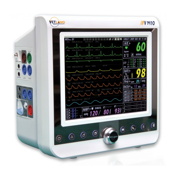
V1410 / V1412 User Manual 7. V1410 / V1412 Overview V1410 Monitor (10.4” Display) V1412 (12.1” Display) -
Page 17: V1410 / V1412 Components
V1410 / V1412 User Manual 8. V1410 / V1412 Components Monitor Front Operation Panel Description Description Freeze Button Power Button NIBP Start/Stop Button Alarm ON/OFF Button Print Start/Stop Button Event Save Button Exit Button Screen Button Menu Button... - Page 18 V1410 / V1412 User Manual Right Side (Printer Option) Description Description Print Door Print Feed Button Print Power LED Speaker Print Error LED...
-
Page 19: Left Side
V1410 / V1412 User Manual Left Side <Microstream EtCo2> <Sidestream / Mainstream EtCO2> Description Description NIBP Connection Terminal Module Connection Terminal (Option) SpO2 Connection Terminal Output Connection Terminal (Option) EKG Connection Terminal Input Connection Terminal (Option) ECG/RESP Connection Terminal TEMP 4 Connection Terminal (Option) -
Page 20: Back Side
V1410 / V1412 User Manual Back Side Description Description Handle RS232 Port Ground Port LAN Port MAIN Power Switch ECG Out Port (Option) AC Power Input Port SD Card Slot VGA Port (Option) -
Page 21: Display Symbols
V1410 / V1412 User Manual 9. Display Symbols Symbol Description Symbol Description Type CF Product, Power Switch Defibrillation Protected Type BF Product, Alarm On/Off Defibrillation Protected Type BF Product Alarm Event Attention, Warning Screen Change (Screen) Consult Accompanying Documents IPX-0... -
Page 22: Display Screen
V1410 / V1412 User Manual 10. Display Screen Description Description Description NIBP PR Measurement Bed Number EtCO2 Expiratory Measurement Function Icon EtCO2 Inspiratory Measurement NIBP Systolic Default Set Respiration Measurement NIBP Diastolic Date & Time IBP PR Measurement NIBP Mean... -
Page 23: Explanation Of Screens
V1410 / V1412 User Manual 11. Explanation of Screens Pressing the Screen button allows you to sequentially view the following six screens: 1. Main Screen . ECG 7 leads Screen (Use for ECG 5 Leads Cable 3. ESN Screen 4. Numeric Screen 5. -
Page 24: Explanation Of Screen Icons
V1410 / V1412 User Manual 12. Explanation of Screen Icons Icon Meaning Display Action Flashes at 1-second interval ECG Lead Fault & Lead Off Flashes at 1-second interval Arrhythmia Detect ST Detect Fixed Pacemaker Detect Flashes at 1-second interval SpO2 Signal not detected... -
Page 25: How To Use The V1410 / V1412 Monitor
V1410 / V1412 User Manual 13. How to Use the V1410 / V1412 Monitor Turn on the main power switch at the back of the product. Press the power switch for 1-2 seconds. If you want to change the setting value etc. during use, press the Menu button to change the setting values per each measurement parameter. -
Page 26: Alarms
V1410 / V1412 User Manual 14. Alarms The V1410 / V1412 provides a variety of alarms to advise the user of changing patient data being received that are outside the alarm parameters set. Please read carefully the contents of this section in order to learn how to interpret and react appropriately to the alarms. -
Page 27: How To Set Alarms
V1410 / V1412 User Manual How to Set Alarms To change the alarm setting, press the Menu button once to select ALARM. Turn the Menu button clockwise or counterclockwise to select the parameter. To change from high to low alarm range, press the Menu button. -
Page 28: Alarm Range
V1410 / V1412 User Manual Alarm Range Setting Range Parameter HIGH TYPE SETUP_SILENCE TIME 1 – 5 MINUTES ECG [bpm] 0 – 300, OFF 0 – 300, OFF DIAGNOSIS [mm] 0.1 – 9.9, OFF 0.1 – 9.9, OFF SpO2 [%] 0 –... -
Page 29: Trend Display
V1410 / V1412 User Manual 15. Trend Display ● ● ● ● ● ● Description Description Trend Data Saving Date and Time Trace 3 Trace 1 Trend Data Trace 2 Selection Bar Alarm interval displays in red. Data prints out 5 previous readings and 5 subsequent readings as well as the current reading. -
Page 30: Checking Trend Data
To select the parameter type, press the Menu button and select TRACE on the Trend menu. The V1410 / V1412 supports graph trend data allowing you to easily check a patient’s status. Trend data can be saved for 7 days in 1 minute intervals. - Page 31 V1410 / V1412 User Manual To delete trend data, select INITIAL on the Trend menu. If you select EXECUTE, all of the trend data is deleted. Make sure you intend to delete the data before selecting this option. Caution To change to the Main screen after the trend data check, select RETURN and press the Screen button one time.
-
Page 32: Trend Data Save & Load
V1410 / V1412 User Manual Trend Data Save & Load To save Trend Data to an SD Card, insert the SD Card in the SD Card port on the back of the monitor. Then, press the Menu button on the Trend screen and select TREND ... -
Page 33: Event Display
V1410 / V1412 User Manual 16. Event Display Description Description Event Data List 0.2 second Analysis Bar Event Data Number Trace 1 Wave Auto or Manual Record Indicator Trace 2 wave Alarm Display Window Trace 3 Wave Arrhythmia Display Window... -
Page 34: Checking Event Data
V1410 / V1412 User Manual 17. Checking Event Data To check Event Data, press the Screen button until the Event display appears. 1) Select the desired Data on the Event Data list by turning the Menu button and pressing the Menu button one time. - Page 35 V1410 / V1412 User Manual To print out event data, select PRINT on the Event menu to set Channel 1/2/3 and Size, and press the Print button. Channel 1/2/3 is the wave to be printed out. Size is the length of the printer paper. (You can print in 25 mm increments Note from a length of 150 mm to 300 mm.)
-
Page 36: Setup
V1410 / V1412 User Manual 18. Setup Set print, volume, and language as follows: To change the Setup, press the Menu button one time to select the Setup menu. To select the desired menu, turn the Menu button clockwise or counterclockwise. - Page 37 V1410 / V1412 User Manual Setup Menu Range Description YEAR: 2000 – 2100 MONTH: 1 – 12 TIME/DATE DATE: 1 – 31 Input Date and Time HOUR: 0 – 23 MINUTE: 0 – 59 Input hospital name, patient PATIENT INFO.
-
Page 38: Mini-Trend Function
V1410 / V1412 User Manual 19. Mini-Trend Function The Mini-Trend function displays 2 hours of the patient’s trend data. Check the patient’s Mini-Trend data as follows: To check Mini-Trend data, push the Menu button one time on the Main screen, and select SETUP ... -
Page 39: Oxy-Crg Function
V1410 / V1412 User Manual 20. Oxy-CRG Function This function displays the trend change of the patient’s heart rate, SpO2, and respiration in detail. Use this function as follows: To view OXY-CRG data, push the Menu button one time on the Main screen and select SETUP ... - Page 40 V1410 / V1412 User Manual To delete the data, select INITIAL CLEAR EXECUTE on the OXY-CRG menu. To close the OXY-CRG data screen, select EXIT on the OXY-CRG menu. OXY-CRG data Make sure you want to delete the before selecting EXECUTE. Once you select EXECUTE, all saved OXY-CRG data is deleted.
-
Page 41: Ecg Recall Function
V1410 / V1412 User Manual 21. ECG Recall Function This function saves the ECG wave and numerical values when an alarm is ringing or when the user pushes the EVENT SAVE button. Use this function as follows: To see ECG Recall Data, push Menu switch one time on Main screen and select SETUP ... - Page 42 V1410 / V1412 User Manual Control the gain of the saved wave by selecting GAIN on the ECG Recall screen and selecting 5, 10, 20, 30, or 40 mm/mV. To delete data, select INITIAL CLEAR EXECUTE on the ECG Recall menu.
-
Page 43: Drug Dose Calculation
V1410 / V1412 User Manual 22. Drug Dose Calculation Description Drug Name: Dopamine, dobutamine, epinephrine, aminophylline, nipride, nitroglycerin, heparin, diazepam, penicillin, pitocin, insulin, lidocaline, fentany1, procainamide, cephalothin-cefobid, drug A-E Weight of Patient (kg) Total Dosage Volume of Diluted Solution Dosage Unit: DOSE/hr, DOSE/min... - Page 44 Calculation value is not standard for dosage, because drug dosage depends on the patient’s condition and environment. Caution Drug types not specified in the V1410 / V1412 list of drug names can cause calculation errors. The user must consult with a qualified veterinary professional before setting the patient’s dosage. WARNING Set the patient’s drug dosage as follows:...
- Page 45 V1410 / V1412 User Manual To check and view the chart, select SCROLL and turn the Menu button. To close the titration chart, select EXIT. To close the drug calculation screen, select EXIT. The Drug Dose Calculation function is only available on the Main screen. If you push the Screen button, this function will be canceled.
-
Page 46: Patient Information Setup
V1410 / V1412 User Manual 23. Patient Information Setup To input patient’s information, push the Menu button one time on Main screen and select SETUP PATIENT INFO. Select each of the following labels and enter the patient’s information: •... -
Page 47: Default Settings
V1410 / V1412 User Manual 24. Default Settings When you select DEFAULT SETTINGS, all setting values are changed to the values saved at the factory without you having to change the setting values for each parameter. The default settings are as follows:... - Page 48 V1410 / V1412 User Manual Parameter Item Name VET_Large VET_Small CH 1 TRACE ON TRACE ON CH 2 TRACE ON TRACE ON TRACE CH 3 TRACE OFF TRACE OFF CH 4 TRACE OFF TRACE OFF TEMP ◦ ◦ UNIT ◦...
- Page 49 V1410 / V1412 User Manual Parameter Item Name VET_Large VET_Small CH 1 CH 2 12.5 mm/sec 12.5 mm/sec SPEED CH 3 CH 4 CH 1 CH 2 LABEL CH 3 CH 4 Arterial Label Group: ABP HIGH 90/60 (70) 90/60 (70)
-
Page 50: Printer Settings (Optional)
V1410 / V1412 User Manual 25. Printer Settings (Optional) The patient’s information can be printed out using the printer as follows: To change the print setup, press the Menu button one time and select the SETUP PRINTER menu. Select the desired setting by turning the Menu button clockwise or counterclockwise. -
Page 51: Printed Data Examples
V1410 / V1412 User Manual Printed Data Examples <Trend Printing> <Wave Printing> Loading Printer Paper Open the printer door by pressing the button on both sides of the printer slightly as shown in the figure below. Remove the empty paper core and insert a new paper roll making sure that it is properly oriented. -
Page 52: Setting Wave Color
V1410 / V1412 User Manual 26. Setting Wave Color This section describes how to change the wave color of each parameter and its numeric value. Wave and numeric value color change method: To change the wave color and numeric value, press the Menu button one time on the Main screen and select SETUP ... -
Page 53: Power & Battery Specifications
V1410 / V1412 User Manual 27. Power & Battery Specifications Both AC and DC power is used for The V1410 / V1412. AC power normally used, but a rechargeable battery providing DC power is available for portable use. AC Power (100–240 VAC) If the AC power is connected to the main body of the product, a light-green color lights up on the AC LED on the front. - Page 54 The life expectancy of the battery is nearing its end when 30% charge /discharge ratio is occurring. Please contact Vetland Medical to arrange delivery of a replacement battery pack. The battery is easily exchanged via the battery access port. Do not disassemble the monitor as damage may occur.
-
Page 55: Ecg Measurement
Check if the ECG cable is damaged before taking the ECG measurement. A damaged ECG cable will not transmit electrical impulses correctly and will cause erroneous readings. Use only a VETLAND genuine ECG Cable with the V1410 / V1412. Other ECG cables may cause improper performance and/or provide inadequate protection during defibrillation. WARNING ... - Page 56 V1410 / V1412 User Manual Attach a patient’s electrode to the sites shown below. <Standard 3 Electrode Placement> AAMI Attaching site Electrode Electrode Lead Lead Color Color White Just below the clavicle (scapula) near the right shoulder Yellow Black Just below the clavicle (scapula) near the left shoulder...
-
Page 57: Ecg Lead Change
V1410 / V1412 User Manual ECG Lead Change To change the ECG1 lead waveform setting, press Menu button one time on the Main screen. Select ECG LEAD CH 1 and then select the lead. Change the ECG2 and ECG3 lead waveform settings using the same method used in Step 1, except select CH 2 and then CH3. -
Page 58: Ecg Out Function (Optional)
V1410 / V1412 User Manual ECG Out Function (Optional) The V1410 / V1412 provides ECG analog/pulse wave output from a rear stereo connector. It can be used with defibrillator sync input or other medical devices. How to Get ECG Output Connect the cable to the rear radio connector of the V1410 / V1412. -
Page 59: St Analysis
Although studied widely in human medicine, arrhythmia measurements have not been validated in veterinary medicine and are offered only as an ancillary tool. NOTE The V1410 / V1412 is designed to independently display the ST level for each lead view. NOTE <ST Level Displaying START Screen>... -
Page 60: Arrhythmia Display
Because there are a great variety of species, and rhythms do vary between species, the V1410 / V1412 arrhythmia analysis is only intended to be a helpful tool for which a trained, qualified veterinary professional should ultimately decipher and prescribe intervention based on their medical opinion. -
Page 61: Arrhythmia Guide
PCV is detected before finishing T wave in the normal ECG R-on-T wave. The V1410 / V1412 provides 13 types of arrhythmia display in two alarm levels: - High Alarm: VTAC, ASY - Low Alarm: PVC, BGM, TGM, TAC, BRD, VENT, VFIB, CPT, TPT, MIB, R-on-T ... -
Page 62: Pacemaker Detection
V1410 / V1412 User Manual 31. Pacemaker Detection When pacemaker detection is ON, a red bar indicating pacemaker detection input periodically displays on the ECG waveform. Detect a pacemaker as follows: Press the MENU button once and select ECG CONFIG ... -
Page 63: Respiration Measurement
V1410 / V1412 User Manual 32. Respiration Measurement Changes in the chest impedance resulting from the patient’s respiration is measured and displayed as a waveform and the values will appear on the screen. How to Measure Respiration Connect the ECG cable to the ECG connection terminal of the measurement module. -
Page 64: Changing The Respiration Waveform
V1410 / V1412 User Manual Respiration signals may be distorted due to radiated electromagnetic interference from an ESU or other electromagnetic devices. Should this occur, try repositioning the ESU further away or investigate with the manufacturer the possibility of utilizing a higher rated shielded CAUTION cable. -
Page 65: Hrv Measurement
V1410 / V1412 User Manual 33. HRV Measurement The autonomic nervous system affecting the cardiac pacemaker cell in sinoatrial node (SA node) determines the heart rate. The SA node is controlled by the sympathetic and parasympathetic nervous system. Heart rate is determined by these opposite nervous systems harmonized with each other. The beat-to-beat interval is a physiological phenomenon that is analyzed for possible indication of the health of the cardiac system as well as external influences to the body such as pain. -
Page 66: How To Interpret The Hrv Distribution Graph
V1410 / V1412 User Manual How to Interpret the HRV Distribution Graph Normal status Hypertension, stressed, sympathomimetic status Arrhythmia, excitation, sympathomimetic status Overstrain, geriatric, parasympathomimetic status... -
Page 67: Nibp Measurement
Use only a Vetland NIBP cuff with the V1410 / V1412. Other NIBP cuffs may cause improper performance due to tubing diameter or bladder compliance not meeting specifications. -
Page 68: Blood Pressure Basics
V1410 / V1412 User Manual Blood Pressure Basics An anesthetized patient’s blood pressure should be regularly monitored. The V1410 / V1412 Patient Monitor uses the oscillometric method to obtain systolic, diastolic, and mean non-invasive blood pressure measurements. Most text books advise maintaining systolic blood pressure (SAP) at or above 90 mmHg and mean arterial blood pressure (MAP) above 70 mmHg. -
Page 69: Nibp Measurement Screen
Manual Measurement Indicator NIBP Manual Measurement Connect one end of the NIPB hose to the V1410 / V1412 and the other end to the NIBP cuff. Position the NIBP cuff in the appropriate location for the patient being monitored. See Blood Pressure Basics on page 68. -
Page 70: Nibp Auto Measurements
V1410 / V1412 User Manual NIBP Auto Measurements Auto function will be canceled when changing the INTERVAL setting during auto measurement. CAUTION NIBP Auto (Long Term Automatic Mode) Measurement Method This mode measures continually according to the interval set up by the user. - Page 71 V1410 / V1412 User Manual Changing the NIBP Unit of Blood Pressure To change the unit of blood pressure, select UNIT in the NIBP Menu and set the desired unit. Setting Mode Range Description MODE AUTO, MANUAL, Set the automatic measurement.
- Page 72 V1410 / V1412 User Manual NIBP Auto (Short Term Automatic Mode) Measurement Method This mode cancels after measuring the NIBP several times during a user set time interval. To start the automatic (AUTO) NIBP measurement, select NIBP STAT TIME at Menu and select the desired measuring time.
- Page 73 V1410 / V1412 User Manual VENOUS STAT Function This function is used to easily find a patient’s vein by controlling the flow of the vein by maintaining constant pressure to the cuff. Press the Menu button once and select, NIBP ...
-
Page 74: Nibp Trend Screen
V1410 / V1412 User Manual NIBP Trend Screen NIBP Trend Data Check Method Using NIBP Trend Screen: Select NIBP TREND SCREEN ON on the menu. The NIBP Trend Screen displays. NIBP Trend Data Delete Method: Select NIBP ... -
Page 75: Spo2 Measurement
V1410 / V1412 User Manual 35. SpO2 Measurement The concentration of oxygen saturation (SpO2) means the saturation level of hemoglobin which can transport the oxygen of the arterial blood. The current transport level for the capacity of hemoglobin to transport the oxygen is expressed as a percentage. -
Page 76: Spo2 Measurement Display
V1410 / V1412 User Manual SpO2 Measurement Display ● ● ● ● ● Description Description SpO2 Waveform Speed, Size SpO2 Pulse Bar SpO2 Waveform SpO2 Measurement Numeric SpO2 Alarm Range How to Measure SpO2 Connect the SpO2 connector to the equipment and attach the SpO2 sensor to the patient’s tongue, toe... -
Page 77: Changing Spo2 Waveform Size And Speed
V1410 / V1412 User Manual Changing SpO2 Waveform Size and Speed To change SpO2 waveform size, press the Menu button one time and select SpO2 GAIN. To change SpO2 waveform speed, Press Menu button one time and select SpO2 SPEED. -
Page 78: Apg Measurement
V1410 / V1412 User Manual 36. APG Measurement APG Defined The plethysmogram waveform represents pulsatile peripheral blood flow, which reflects both peripheral and central hemodynamics. Photoplethysmography (PPG) uses infrared light transmitted through the skin to non-invasively measure hemodynamic parameters. Photoplethysmography is thus a useful measure of vascular dysfunction and heart rate variability. -
Page 79: Apg Application
V1410 / V1412 User Manual APG Application The age of a blood vessel is determined by the elasticity of the blood vessel using APG. The APG is expressed as a number from 1-8. The higher the number, the less elastic the vessel. -
Page 80: Temperature Measurement
V1410 / V1412 User Manual 37. Temperature Measurement Changes in impedance according to the change in a patient’s body temperature is perceived by the temperature sensor, and then displayed numerically on the screen after a series of calculations. Temperature Measurement Screen... -
Page 81: Ibp Measurement
While the heart is contracting and relaxing, the sensor measures the variations in pressure. Do not reuse the disposable transducer. WARNING Only the transducer specified by Vetland Medical can be used. Each IBP operates independently and requires independent setups. CAUTION IBP Measurement Screen ●... -
Page 82: Composition Of Monitoring Accessories
V1410 / V1412 User Manual Composition of Monitoring Accessories LINE TO PATIENT... -
Page 83: How To Connect The Ibp Cable
V1410 / V1412 User Manual How to Connect the IBP Cable Connect the monitor interface cable to the IBP input connector. Hold the back side of the clear cover surrounding the connector, and connect the converter to the reusable monitor interface. - Page 84 V1410 / V1412 User Manual How to Use Flush: Hold both sides of the flush operator and pull upward gently. If a fast flush is performed on the animal, the user should check carefully for the presence of foam and particulate matter.
-
Page 85: Adjustment Of Zero Point Of The Converter
V1410 / V1412 User Manual << Priming and Tips >> Priming should be done slowly! - Slow priming will lessen the effort to remove air bubbles afterward. Prime using gravity! NOTE - Do not over pressurize. If small bubbles flow too slowly inside the system, lift up the supply bag. -
Page 86: Changing The Ibp Label
V1410 / V1412 User Manual Table for Labels According to the Site of Measurement Label Site Measurement Artery group throughout the whole body Arterial Blood Pressure (systemic) Central Venous Pressure Central vein / atrium group Intracranial Pressure Intracranial group Pulmonary Arterial Pressure... -
Page 87: Etco2 Measurement (Optional)
50 ml/min reduced inspiratory volume. The sampling outlet of the V1410 / V1412 should be attached to an active scavenging WARNING system to evacuate the anesthetic gases discharged by the patient. -
Page 88: Microstream Co Calibration
V1410 / V1412 User Manual Microstream CO Calibration The accuracy validation for the Microstream CO function is performed once a year or when the measurement results are not accurate. It is recommended to use 5% gas for calibration and the microstream filter line. -
Page 89: Microstream Co 2 Measurement Method
The respiration value is automatically changed when the EtCO2 is measured. It will display the changes of impedance. The EtCO2 and FiCO2 will be displayed on the V1410 / V1412 screen after 3 seconds when it detects proper input. The EtCO2 waveform and data are displayed. If the waveform is not displayed on the screen, select Menu ... -
Page 90: Microstream Co2 Messages
V1410 / V1412 User Manual Microstream CO2 Messages Messages – Measurement Mode Message Description Initializing the EtCO2 Module when power on. It doesn’t measure INITIALIZATION during this time. FILTERLINE NOT The filter line is not connected to the EtCO2 accessory. - Page 91 V1410 / V1412 User Manual Messages – Calibration Mode Message Description FILTERLINE NOT The filter line is not connected. CONNECTED CALIBRATION IN The calibration is in progress. PROGRESS Not ready to calibrate the EtCO2 Module. CALIBRATION NOT READY (Run calibration after a while) CALIBRATION GAS Remove the EtCO2 calibration gas from the accessory.
-
Page 92: Mainstream And Sidestream Co Calibration
V1410 / V1412 User Manual Mainstream and Sidestream CO Calibration Calibration should be executed at the following times: – New patient – When turning on/off the patient monitor – When connecting or disconnecting EtCO2 module and sensor – When a ZERO REQUIRED message appears during measurement. -
Page 93: Mainstream Co Measurement Method
EtCO2 sensor is connected to the monitor, the measurement is prioritized to pull the respiration data from the EtCO2 sensor. The EtCO2 and FiCO2 will be displayed on the V1410 / V1412 screen 15 seconds after a successful detection of exhaled breath. -
Page 94: Sidestream Co Measurement Method
EtCO2 sensor is connected to the monitor, the measurement is prioritized to pull the respiration data from the EtCO2 sensor. EtCO2 and FiCO2 will be displayed on the V1410 / V1412 screen 15 seconds after a successful detection of exhaled breath. -
Page 95: Mainstream/Sidestream Co Messages
V1410 / V1412 User Manual Mainstream/Sidestream CO Messages Message Description EtCO2 module is connected to the monitor SENSOR WARM_UP and is ready to operate. Sample line is disconnected or disassembled from SAMPLE LINE DISCONNECT the module during measurement. Measurement numeric value (or pressure) has... -
Page 96: Troubleshooting
V1410 / V1412 User Manual 40. Troubleshooting This section shows how to remedy simple problems encountered during use. Problems in Display Problem Remedy 1. Check if the main switch at the back of the monitor is No power. 2. Check if AC power is supplied. -
Page 97: Problems In Spo2 Measurement
V1410 / V1412 User Manual Problems in SpO2 Measurement Problem Remedy 1. Check if the probe is affected by strong light in the area. 2. Check if the connection is normal; if the red light of the sensor Flashes or does not turn on, it is an inferior probe. -
Page 98: Problems In Etco2 Measurement (Microstream)
V1410 / V1412 User Manual Problems in EtCO2 Measurement (Microstream) Problem Remedy FILTER LINE NOT The filter line is not connected to the main body. CONNECTED Message Connect filter line. displays. 1. Verify the sample line is not occluded. EtCO2 waveform and data 2. -
Page 99: Product Specifications
Monitor Performances Specifications - TFT Color LCD Display - Waveform Display Method: Scroll - Display Size: V1412 (12.1 inches) / V1410 (10.4 inches) - Resolution : VGA (800 x 600) - Sweep Speed: 6.25, 12.5, 25, 50 mm/sec - Display waveform Time: 2.5 sec. - Page 100 V1410 / V1412 User Manual - DC Offset: -300 mV to 300 mV - Arrhythmia Display (TAC, BRD, PVC, VTAC, ASY, BGM, TGM, VENT, VFIB, CPT, TPT, MIB, R on T) - HR Calculation: 4 – 16 bit Heart Rate - Measurement Range: 0 –...
- Page 101 V1410 / V1412 User Manual Respiration - Measurement Range: 0 – 200 bpm - Accuracy: ±2% or ±2 bpm - Sweep Speed: 6.25, 12.5, 25, 50 mm/sec - Waveform Amplitude: x0.25, x0.5, x1, x2, x3, x4, AUTO - Apnea Alarm Range: OFF, 10 – 40 sec ...
- Page 102 V1410 / V1412 User Manual EtCO2 (End-Tidal CO2) – Optional • Microstream - Measurement Mode: Microstream - Range: 0 – 99mmHg - Temperature: 0 – 50 ℃ - Accuracy: Time * CO Density Accuracy 0–38 mmHg ±4 mmHg 0 – 20 min 39–99 mmHg...
- Page 103 V1410 / V1412 User Manual Accuracy: 0 – 40 mmHg ±2 mmHg - CO 41 – 70 mmHg ±5% of reading 71 – 100 mmHg ±8% of reading 101 – 150 mmHg ±10% of reading - Respiration Measurement Range: 0 – 150 bpm - Respiration Accuracy: ±1 bpm...
- Page 104 V1410 / V1412 User Manual Printer (3 CH) - Optional - Print Method: Thermal - Type: Internal - Print Mode: a. Both (Max 3 Wave) + Trend b. Wave (Max 3 Wave) c. Trend - Paper Width: 57 mm - Valid Width: 150 –...
- Page 105 V1410 / V1412 User Manual Standard Accessories - Patient Cable (3 leads) 1 ea - ECG Clips 3 ea - NIBP Cuff (#2, #3, #4) 3 ea - Gray Hose for NIBP Cuff 1 ea - Power Cord 1 ea...
-
Page 106: Safety
If this occurs often, Vetland Medical suggests a review of the environment in which the system is being used, to identity possible sources of radiated emissions. These emissions could be from other electrical devices used within the same room or an adjacent room. -
Page 107: Electromagnetic Emission
V1410 / V1412 User Manual Electromagnetic Emission The V1410 / V1412 Monitor is intended for use within a specified electromagnetic environment as described below: Emissions Compliance Electromagnetic Environment - Guidance The V1410 / V1412 uses RF energy only for its internal RF emissions function. -
Page 108: Electromagnetic Immunity
On Power Supply operation during power main interruptions, it is recommended Input Lines 40% U 40% U that the V1410 / V1412 be (60% dip in U (60% dip in U powered from an uninterruptible IEC 61000-4-11 for 5 cycle for 5 cycle power supply or a battery. - Page 109 If the measured field strength in the location in which the V1410 / V1412 is used exceeds the applicable RF compliance level above, the V1410 / V1412 should be observed to verify normal operation. If abnormal performance is observed, additional measures may be necessary, such as reorienting or relocating the V1410 / V1412.
-
Page 110: Recommended Rf Separation Distance
V1410 / V1412 User Manual Recommended RF Separation Distance The V1410 / V1412 Monitor is intended for use in an electromagnetic environment in which radiated RF disturbances are controlled. The customer or the user of the V1410 / V1412 can help prevent... -
Page 111: Product Information
43. Product Information Product Warranty All Vetland Medical Sales and Services, L.L.C. products are guaranteed to be free of defects for a period of three (3) years from the date of delivery and shall include workmanship and material. The following are exceptions to this warranty: •... -
Page 112: Payment Terms
Any shortages or errors in shipment of goods must be reported to Vetland within two (2) weeks of date of shipment in order for corrective action to be taken. -
Page 113: Limitation Of Liability
All Vetland products are ONLY to be used for VETERINARY purposes. Vetland products are not designed to be used for human patients. Vetland’s liability whether arising out of or related to manufacture and sale of the goods, their installation, demonstration, sales representation, use, performance, or otherwise, including any liability based upon Vetland’s Product Warranty is subject to and limited to the exclusive terms and conditions as forth above,...
Need help?
Do you have a question about the V1410 and is the answer not in the manual?
Questions and answers