
Subscribe to Our Youtube Channel
Related Manuals for Gatekeeper Y724


Summary of Contents for Gatekeeper Y724
- Page 1 Y724 User Operating Manual Document Ref. No. : DN3089 Version No. : 2.2 Document Date : March 2019...
-
Page 2: Table Of Contents
1.2.3 - Operating the Y724 ........................7 1.2.4 - Updating the Y724 ........................8 1.2.5 - Repairing the Y724 ........................8 2 – THE Y724 AT A GLANCE ........................9 2.1 - T ........................9 ECHNICAL PECIFICATIONS 2.2 - Y724 F ................... - Page 3 4.5.5 – System Information: Environment ..................... 33 4.5.6 – System Information: Storage ...................... 34 4.5.7 – System Information: ECO-Driving Status Info ................34 4.5.8 – System Information: ECO-Driving OBD Data ................35 4.5.9 – System Information: ECO-Driving 6Axis Data ................35 4.5.10 –...
- Page 4 ONFIGURING UBSTREAM ECORDING UALITY 9.4 - U Y724 F ......................138 PGRADING IRMWARE 10 - Y724 INSTALLATION INSTRUCTIONS ..................... 138 10.1 - M Y724 ........................139 OUNTING THE 10.2 - C ........................139 AMERA OUNTING 10.3 - W ........................140...
- Page 5 Y724 User Operating Manual GLOSSARY Term/Abbreviation Description Accelerometer Digital Video Recorder – a device which records audio and video input from the cameras and stores it to a hard disk drive and/or an SD card for retrieval and viewing. Global Positioning System – it is a radio navigation system that...
- Page 6 Y724 User Operating Manual Media Access Control address – it is a unique identifier assigned to MAC Address network interfaces for communications on the physical network segment. On Screen Display – an image superimposed on a screen commonly used to display information such as volume, channel, date/time, device status, etc.
-
Page 7: Introduction
These safety precautions pages are intended to prevent injury to yourself or others, and to prevent damage to the equipment. Always ensure that the Y724 is used correctly and in accordance with the listed instructions, and be sure to also check the manuals included with any other Gatekeeper product accessories (or third-party equipment) that you may use. -
Page 8: Updating The Y724
Applying this firmware to any other Gatekeeper Systems DVR will void the product warranty. 1.2.5 - Repairing the Y724 Your Y724 does not have any user-serviceable parts. Do not open or disassemble it or § attempt to repair it or replace any components. -
Page 9: The Y724 At A Glance
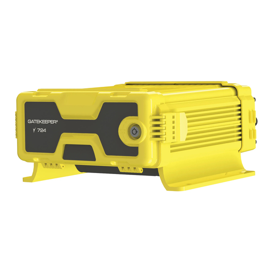
Y724 User Operating Manual 2 – The Y724 at a Glance 2.1 - Technical Specifications Front: Security Door Closed Rear: Ports and Connectors Y724 Technical Specifications Video Video Channels 24 channels supported. IP Camera (16 channels directly on DVR, plus 8 channels with 8 port switch) -
Page 10: Y724 Front View: Security Door Open
Operating Temperature +14°F to +158°F (-10℃ to +70℃) Operating Relative Humidity 8%-90% non-condensing 2.2 - Y724 Front View: Security Door Open Hard Drive Retaining Screws (x3): Remove to access on-board SSDs. SD Card / SIM Card Port : Slide the door to the right to access the port. Ensure that the door is closed prior to powering up the Y724 device. -
Page 11: Y724 Rear View: Ports & Connectors
: Port to connect external USB flash memory drive. Y724 Handle : Handle for use in removing the hard disk (SSD) drive enclosure. 2.3 - Y724 Rear View: Ports & Connectors USB Port : Standard USB 2.0 B connection. 6 Pin Power Port : 6 PIN 8~36V. -
Page 12: Whats In The Box
Gatekeeper sales manager about a Gatekeeper’s Wireless solution). 3G/4G Port (Currently Unsupported, : EVDO/TD-SCDMA/WCDMA/TDD-LTE/FDD-LTE please speak with your Gatekeeper sales manager about Gatekeeper’s MWM solution). 2.4 - What’s in the Box Y724 Digital Video Recorder (Y724 Assembly) Mobile digital video recorder with best-in- class video performance in a stable, reliable, and secure form factor. -
Page 13: Optional Peripherals & Accessories
The infrared (IR) remote control can be used to access the Y724’s menu system Finger Mouse (part number: FDM-G51) * Includes accompanying LCD monitor The trackball mouse can be used to access the Y724’s menu system through a simple point- and-click interface. 13 of 149... -
Page 14: Getting Started With The Y724
Tri-Coloured Driver Alert Button (part number: G4-Y724-DrvAlert) COMRAD™ Docking Station (part number:) External docking station for use in retrieving, viewing, and administering recorded video data. 3 – Getting Started with the Y724 14 of 149... -
Page 15: Powering Up
Y724 User Operating Manual 3.1 – Powering Up The Y724 is installed to make use of your vehicle’s power supply, and the device will be powered on when your vehicle is in operation. The device will automatically shut down after a 5-minute interval after the vehicle is powered off (default setting). -
Page 16: Default Login Credentials
Y724 User Operating Manual Access from the Main Menu: REC Search § Log Search § Setup (* this function requires the user to be logged in as an administrator) § When attempting to access any of these functions, the system will check the user status of before granting access. -
Page 17: Login Step-By-Step
Y724 User Operating Manual 3.2.2 – Login Step-by-Step Step 1 The system will display the log-in dialog box as shown below. § User Name Click on the drop down (v) button at the right corner of the field. § A drop-down menu will appear which will list all the users who are set up to §... -
Page 18: Navigating The Y724
3.3 – Navigating the Y724 Users can choose from three intuitive navigation devices with which to operate the Y724. Depending on your product package, your Y724 will have come bundled with one of the three following devices: 1) The Interactive Control... -
Page 19: The Interactive Control Display (Or 'Icd')
Y724 User Operating Manual 3.3.1 - The Interactive Control Display (or ‘ICD’) The ICD operates using a § touch screen interface and numeric keypad. Actions can be performed by touching or tapping the on-screen buttons / options, or by using the appropriate keypad buttons. -
Page 20: The Finger Mouse
Y724 User Operating Manual 3.3.2 - The Finger Mouse Use the finger mouse track-ball to position the on- § screen pointer over the buttons / options, and click the trigger or mouse buttons to execute an action. Right Button: When viewing video streams, §... -
Page 21: Navigating On-Screen Views
Y724 User Operating Manual Arrow Keys : These buttons can be used to move the cursor or menu highlight to the left § and right as well as up and down in order to select a button or menu item. -
Page 22: Double Camera On-Screen View
Y724 User Operating Manual You can also cycle through the channels iteratively by pressing the key zero [0] on the IR § Remote Control or the ICD2. Cycling through the Video Channels in Single View 3.4.2 - Double Camera On-Screen View In Double Camera On-screen View mode, the screen is split into two sections (using a split video frame layout) and video from two cameras are shown simultaneously on the screen. -
Page 23: Nine Camera On-Screen View
Y724 User Operating Manual 3.4.3 – Nine Camera On-Screen View In 9 Camera On-screen View mode, the screen is split into nine sections (using a 3x3 grid layout) and video from nine cameras is simultaneously shown on the screen. In order to select a specific camera for viewing, you may press any of the keys [1-9] on the §... -
Page 24: The "Video Loss" Display
Y724 User Operating Manual 3.4.4 – The “Video Loss” Display Channels which do not have cameras configured on them will just show a black display. § Any channel which is configured with a camera but is not receiving any video signal from §... - Page 25 Y724 User Operating Manual Action IR Remote Finger Mouse ICD2 Use the Arrow Keys to Navigating through the Move the on-screen Use your finger to tap the pointer using the Track screens. move the cursor to desired menu option. Ball and point to the highlight different menu options.
- Page 26 Y724 User Operating Manual Action IR Remote Finger Mouse ICD2 been selected. This action can’t be Move the on-screen Tap your finger on the Click and drag an item. pointer using the Track performed using an IR item and continue to Ball until it is situated Remote.
-
Page 27: Y724 Startup Screen Layout
3.6 – Y724 Startup Screen Layout Upon start up, the screen of the Y724 will display live video streams from the cameras attached to the DVR. Users can select and configure how many video channels to be displayed on the screen for monitoring purposes. -
Page 28: The Y724 Menu System
Wirelessly with G4 Connect™” (section 7) found on page 56. 4 – The Y724 Menu System Your Y724 comes equipped with a graphical user interface that provides access to all the device’s features and functions. The Y724 menu system (Quick menu and Main Menu) consists of 6 major sections: Single Camera On-screen View §... -
Page 29: Single
Y724 User Operating Manual The Y724 menu system interface will stay the same regardless of the navigation device used (e.g. ICD, Finger Mouse, or IR Remote Control); but different buttons / gestures, etc., (specific to each control interface) can be used to access common functionality. -
Page 30: Double Camera On-Screen View
Y724 User Operating Manual Cycle through all the camera channels by pressing the [0] key. § 4.2 - Double Camera On-screen View This view splits the screen into two sections that display two cameras on the Double screen. Double Channel Navigation - IR Remote Control & ICD Keypad To select a specific camera, press the keys [1-9] to view the channel. -
Page 31: The Playback Function
Y724 User Operating Manual 4.4 - The Playback function The ‘Playback’ button opens the recorded video playback screen, which gives users immediate access to video recorded from the start of the day (in 00:00:00H format), and proceeding until the current time. For more details on the Playback function refer to section 6.1 "Playback" found on page 46. -
Page 32: System Information: Version Info
Y724 User Operating Manual 4.5.1 – System Information: Version Info This screen shows a summary of the various device hardware identification numbers, and also the version numbers of the firmware that is running on the device. The information displayed includes: Device Name §... -
Page 33: System Information: Server Status
Y724 User Operating Manual The information displayed includes: Location § Location Source § Location Plant Number § Location Angle § Speed § 4.5.4 – System Information: Server Status This screen shows the details of the Center Server that the device is setup for connection to (summarising the connection status and type, as well as the connection address and port number). -
Page 34: System Information: Storage
Y724 User Operating Manual The information displayed includes: Voltage § Device Temperature (°C) § HDD Heater Status § 4.5.6 – System Information: Storage This screen lists the storage devices which are currently attached to the device. It also indicates whether the device is currently recording to the listed storage devices, their total storage capacity, as well as remainder capacity in storage space as well as estimated recording time. -
Page 35: System Information: Eco-Driving Obd Data
Y724 User Operating Manual 4.5.8 – System Information: ECO-Driving OBD Data The information displayed includes: Engine Speed § Vehicle Speed § Coolant Temperature § Total Distance § Fuel Consumption § 4.5.9 – System Information: ECO-Driving 6Axis Data Reserved for future use. -
Page 36: The Main Menu
Reserved for future use. 4.6 – The Main Menu Selecting the Main Menu will display the information screen used to access recorded video data, and the Y724’s configuration settings. The Main Menu screen provides access to a number of functions including: REC Search : Please refer to section 6.2 "REC Search"... -
Page 37: Initial Setup
§ Record options § IPC Setup options § 5.1 – Date & Time Settings It is important to ensure that the date and time is set correctly for the Y724 NVR. Navigate to: Main Menu è Setup è Basic Setup è... - Page 38 Y724 User Operating Manual Date Format General DEFAULT SETTINGS: MONTH/DAY/YEAR § Time Format DEFAULT SETTINGS: 24 Hours § Time Zone DEFAULT SETTINGS: (GMT-08:00) PACIFIC TIME (US & § CANADA) If this is not your time zone, please change this setting as appropriate to the actual time zone that your fleet will be operating in.
-
Page 39: Vehicle Identification Information
Y724 User Operating Manual 5.2 - Vehicle Identification Information Set up the identification information for the device, so that it is tied to the vehicle for easy report generation and tracking purposes. Key in the vehicle and driver information of the vehicle in which the device is mounted in. -
Page 40: Setting Basic Preferences
Y724 User Operating Manual 5.3 - Setting Basic Preferences 5.3.1 – Ignition On/Off Delay Time Setup the ignition on/off delay time. Navigate to: Main Menu Setup Basic Setup Startup è è è ON/OFF Mode ON/OFF DEFAULT SETTINGS: Ignition § Ignition Delay DEFAULT SETTINGS: §... -
Page 41: User Accounts
Y724 User Operating Manual Unit Speed DEFAULT SETTINGS: § Set the preferred speed measurement unit used in your region of operations. Fleets operating in United States will typically use MPH. Fleets operating in most other parts of the world (including Canada) where the metric system is adopted will typically choose KM/H. -
Page 42: Video Recording Settings
5.5 – Video Recording Settings The Y724 has the capability of having up to 24 IP cameras connected at the same time. This next step is a crucial step, where you will select the cameras to record the video from, and also set up the quality and resolution of the recorded video. - Page 43 Y724 User Operating Manual Checkbox – Unselected § Channel Name Main Stream DEFAULT SETTINGS: Channel 1 – set name as – CH1 § Channel 2 – set name as – CH2 § Channel 3 – set name as – CH3 §...
- Page 44 § Encode Mode DEFAULT SETTINGS: For all channels (1 to 24), set the following: § On a Y724 NVR data can be simultaneously HDD Double Dual Stream stored for the main-stream data and the sub- Recording stream data. If enabled, the initial values will be for the main stream and the sub- stream data values to be the same.
-
Page 45: Setting U Pip Cameras
Y724 User Operating Manual using the slider bar stated in HDD Record Duration. If HDD Double Recording is not enabled the whole of the HDD will be utilized for recording of main stream data. DEFAULT SETTINGS: Unchecked § HDD Record Duration Sets the amount of data to be recorded for Main Stream and Sub-stream. -
Page 46: On-Screen Playback Controls
Y724 User Operating Manual 6.1.2 - On-Screen Playback Controls On-screen playback controls allow users to navigate video. Playback controls will auto-hide after 15 seconds of inactivity, and can be displayed again using one of the following methods: ICD Touchscreen: Tap anywhere on the touchscreen to display playback controls. - Page 47 Y724 User Operating Manual : Increase the volume of the audio in the video recording currently being § Increase Volume played back. : Decrease the volume of the audio in the video recording currently being Decrease Volume § played back.
-
Page 48: Rec Search
Y724 User Operating Manual 6.2 - REC Search The REC Search feature is used to search, view, and export recorded video data. Step 1: Select a Video Clip from the ‘Calendar View’ The ‘Rec Search’ dialog makes use of a calendar interface to allow users to easily navigate recorded video data. - Page 49 Step 2: Select Camera Channels In a complex, multi-camera configuration, the Y724 can support up to 24 connected cameras. The Camera Channel dialog allows users to filter data by selecting only the camera channels of interest.
- Page 50 Y724 User Operating Manual : Clicking the ( Search ) button will advance to the playback screen to display § Search recorded video. Step 3: Select a Time Interval for Playback The time interval dialog is used to identify the camera channels and recorded video that will be used for playback, or for export.
- Page 51 Y724 User Operating Manual ˄ : If more than four camera channels have been selected, the ( ) and Scroll Camera Channels § ˅ ) buttons can be used to scroll through available channels. : Displays the selected playback time. Clicking on the slider will open a §...
-
Page 52: Log Search
(SD Card or USB flash drive). space available. If the storage medium is too small, the export will be aborted.) 4. Select the export file format. The Y724 supports two formats: Proprietary Data: The video clip will be exported in a proprietary file format that can be viewed using Gatekeeper Systems software. - Page 53 Y724 User Operating Manual ã : The ( ) button returns to the Main Menu. § Main Menu : The ( ) button will return to the previous screen. § Back to Previous Screen ˄ ˅ : The ( ) and ( ) buttons can be used to select the month.
- Page 54 Y724 User Operating Manual : The 'Log Type' drop-down menu is used to filter logs by type. Options § Select Log Type include: a. Alarm: The log file that lists all alarm events. When an 'Alarm' log is selected, the user will be presented with an additional drop-down that can be used to further refine the filter.
-
Page 55: Interacting Wirelessly With G4 Connect
USB flash drive), and close the dialog. 7 - Interacting Wirelessly with G4 Connect™ You can connect wirelessly to the Y724 by using the G4 Connect™ application (‘app’) installed on any Android operating system compatible mobile device. Step 1: Install the G4 Connect™ application... -
Page 56: The G4 Connect Interface
MAC address (e.g., 000035000AE6). The MAC address, and subsequent network broadcast ID, can be found on a label that is included with the Y724 packaging box. Make sure you have correctly identified this network broadcast ID before proceeding. -
Page 57: The 'Common Tab Your Device S Status
7.2 - The ‘Common’ tab: Device status settings can be viewed by using the ‘Common’ tab in the G4 Connect app. This tab provides insight into the basic operating information for your Y724 device, and includes technical details such as: Basic Info : The current / historical / server / Input &... -
Page 58: The 'Playback Tab Managing Recorded Videoclips
Y724 User Operating Manual Managing Recorded Videoclips 7.4 - The ‘Playback’ tab: Video playback, or viewing data that has been previously recorded, is done through the ‘Playback’ tab. When opening the tab, you will be presented with a calendar view of all the videoclip data recorded to the internal SD card. - Page 59 Y724 User Operating Manual Select the Stream Type and Channel to filter the video data, and then click ‘Next’ to open the video playback timeline. By moving the playback slider (located near the bottom of the panel) you can specify where your video playback will begin.
-
Page 60: Using 'Video Export' To Export A Videoclip
Y724 User Operating Manual The speed button allows you to control the speed of video playback. 7.4.1 - Using ‘Video Export’ to export a videoclip 1. Click ‘Video Export’. 2. Drag the slider to the position in the timeline where you Notice that would like to begin the export. -
Page 61: Tab : Configuring Your Device
Settings’ section found on page 31. 8 - Configuration The Y724 includes a comprehensive configuration menu that can be used to tailor every aspect of the device to your fleet requirements. The configuration menu system consists of 5 major sections: Basic Setup: Configure all the basic device preferences and operational settings. -
Page 62: Configuration Menu Quick Reference
Y724 User Operating Manual 8.1 – Configuration Menu Quick Reference The Y724 supports a wide range of configurable preferences that can be used to configure the device to your specification. The Y724 configuration menu is summarized below. 8.2 – Navigating the Configuration Menu The configuration menus are presented in a tabular format, where the main sections can be selected from the row of tabs at the top of the screen. - Page 63 Y724 User Operating Manual NOTE: If you navigate away from the current page/tab without saving, any changes that you have made to the settings will be discarded. Main Menu: Click this icon to return to the Main Menu. § Back to Previous Screen: Click this icon to return to the Previous Screen that you were at.
-
Page 64: Interface Controls Used For Configuration
Y724 User Operating Manual 8.3 - Interface Controls used for Configuration Interface Control Description Clicking any button either performs an action or advance you to the next step in the process. Button Checkboxes allow you to toggle an item – clicking on it will select it and clicking on a selected item will deselect it. - Page 65 Y724 User Operating Manual the field will display an on-screen keypad for the user to key in numeric values. This is an input field for dates. Clicking on this field will show a calendar from which the user can select the desired date.
-
Page 66: Basic Setup
Y724 User Operating Manual 8.4 - Basic Setup Navigate to: Main Menu Setup Basic Setup è è Basic Setup settings include key operational configurations such as device identifiers and vehicle information, user management, time setup and device startup. 8.4.1 - Regist(ration) Info... - Page 67 Y724 User Operating Manual NOTE: Only set when the device is configured as part of a Gatekeeper Wireless deployment. Vehicle Plate Vehicle Info Alphanumeric text field for setting the vehicle plate number. This is typically the vehicle registration plate number.
-
Page 68: Time Setup
Y724 User Operating Manual 8.4.2 - Time Setup Time Setup Navigate to: Main Menu Setup Basic Setup Time Setup è è è The device contains a real time clock. This subsection enables you to view and set the date and time for the device, and also configure the options used for time synchronization as well as daylight savings. - Page 69 Y724 User Operating Manual in the device. It consists of the following fields: Date field which enables you to set § the current date. Time field which enables you to set § the current time. Drop list which allows you to choose §...
- Page 70 Y724 User Operating Manual Checkbox – Unselected § NTP Sync Checkbox – specifies if the device will synchronize the date and time periodically with a selected Time Server. If this option is selected, you will also need to use the associated drop list to specify which Time Server will be used for the time synchronization.
- Page 71 Y724 User Operating Manual day of the week in the year) (set an actual hard date for Date § when daylight savings is active) DEFAULT SETTINGS: Week § Start This is a set of fields which allow you to choose the starting point of the period for which the device will adjust for daylight savings time.
-
Page 72: Startup
Y724 User Operating Manual Drop list to choose the end month (from JAN to DEC). Drop list to choose the end week (either 1 or LAST). Drop list to choose the end day (from SUNDAY to SATURDAY). Time field to choose the end time. - Page 73 Y724 User Operating Manual Ignition Ignition Delay Sets the additional time period that the device will continue running after the vehicle ignition is off. The device will only stop recording and shutdown after this delay period is past. DEFAULT SETTINGS: §...
-
Page 74: User Setup
Y724 User Operating Manual Battery Low Voltage Numeric text field to set the battery low Protect voltage threshold. If Low Volt Protect is selected, the device will turn off when battery voltage is detected to be consistently below this threshold value. - Page 75 Y724 User Operating Manual Idle Time User Setup Drop list which allows you to set the login time out period. Users will be automatically logged out after the specified period of inactivity: 30 Seconds § 1 Minute § 3 Minutes §...
- Page 76 Y724 User Operating Manual Alphanumeric text field to key in § the user password. Alphanumeric text field to key in § the user password a second time in order to confirm it. For user name, you may input up to a...
-
Page 77: Network
Y724 User Operating Manual 8.4.5 - Network Network Navigate to: Main Menu Setup Basic Setup Network è è è This subsection enables you to view and set up all the network configuration options for the device communications. These include settings for the local network, web port settings, Wi-Fi, communications module, and center server settings. - Page 78 Numeric text field to set the web port number. DEFAULT SETTINGS: § NOTE: THE FOLLOWING SECTION (WIFI) IS ONLY APPLICABLE FOR DVRS EQUIPPED WITH THE INTERNAL WIFI MODULE . GATEKEEPER DOES NOT SUPPORT THIS CONFIGURATION. Enable Wi-Fi Drop list for selecting the Wi-Fi option: Disable §...
- Page 79 IP address of the gateway for the device. DEFAULT SETTINGS: Disabled/not applicable. NOTE: THE FOLLOWING SECTION (COMM) IS ONLY APPLICABLE FOR DVRS EQUIPPED WITH THE INTERNAL CELLULAR MODULE . GATEKEEPER DOES NOT SUPPORT THIS CONFIGURATION. Module Comm Drop list which displays a list of connected communication modules.
- Page 80 Y724 User Operating Manual modify them. These configuration values are module specific. If you have more than one communications module connected, you will need to select each in turn and configure them separately. DEFAULT SETTINGS: Disabled/not applicable. Server Type This field is for display only. It automatically...
- Page 81 Reserved numeric text field. DEFAULT SETTINGS: Disabled/not applicable. Number3 Reserved numeric text field. DEFAULT SETTINGS: Disabled/not applicable. NOTE: THE FOLLOWING SECTION (SERVER) IS ONLY APPLICABLE WHEN THE DEVICE IS BEING CONFIGURED AS PART OF A GATEKEEPER WIRELESS DEPLOYMENT. 81 of 149...
- Page 82 Y724 User Operating Manual Center Server Server Drop list which displays a list of center servers configured in the device. Selecting one of them will display the currently set configuration values, and allow you to modify them. These configuration values are server specific.
- Page 83 Y724 User Operating Manual Local § – Not Supported Wi-Fi § – Not Supported Module1 § – Not Supported Module2 § – Not Supported Auto Adaptation § DEFAULT SETTINGS: Local § Register Server IP Numeric text field to configure the IP address of the message server.
-
Page 84: Application
Y724 User Operating Manual 8.4.6 - Application Application Navigate to: Main Menu Setup Basic Setup Application è è è Reserved for future use. 8.4.7 - Network Other Setup Navigate to: Main Menu Setup Basic Setup Other Setup è è è... -
Page 85: Live View
Y724 User Operating Manual 8.5.1 - Live View Live View Navigate to: Main Menu Setup Surveillance Live View è è è This subsection enables you to configure the settings for the live view of the video coming from the cameras. These settings only affect the video being viewed on the LCD monitor or the ICD2 –... - Page 86 Y724 User Operating Manual Image Setup Menu: The entire image setup menu is floating over the video from the § live camera. You may click and drag the entire image setup menu up and down in order to look at different parts of the image.
- Page 87 Y724 User Operating Manual You may use the (+) and (-) buttons or click and drag the slider knob to adjust the margins of the screen to fit the display within the limitations of your display monitor. This is especially useful if you find that parts of the display are off-screen.
- Page 88 Y724 User Operating Manual You are allowed to select more display channels than there are cameras available. However, the selected display channels which do not have cameras will be displayed in the live view as a black box. DEFAULT SETTINGS: Checkbox –...
- Page 89 Y724 User Operating Manual Mode: This enables you to choose the display mode, whether channels will be displayed § in single, quad or 9-split mode. : Single camera on the screen : Two cameras on the screen in 2x2 grid layout...
- Page 90 Y724 User Operating Manual Auto Loop Checkbox – if selected will enable the auto-loop feature. DEFAULT SETTINGS: Checkbox – Unselected § Date/Time Live OSD Checkbox – if selected, the date and time will be displayed as an overlay text on top of the live video view on the LCD monitor or ICD2.
-
Page 91: Record
Y724 User Operating Manual DEFAULT SETTINGS: Checkbox – Unselected § Checkbox – if selected, the GPS coordinates will be displayed as an overlay text on top of the live video view on the LCD monitor or ICD2. DEFAULT SETTINGS: Checkbox – Unselected §... - Page 92 Y724 User Operating Manual Overwrite The device records video cyclically. This drop list enables you to specify the conditions whereby older video will be overwritten: By Days – video older than a § specified number of days will be overwritten by newer video.
- Page 93 Y724 User Operating Manual DEFAULT SETTINGS: Checkbox – Unselected § Channel Main Stream Drop list which displays the list of available camera channels. Selecting one of them will display the currently set configuration values, and allow you to modify them.
- Page 94 Y724 User Operating Manual Channel 18 – set name as – CH18 § Channel 19 – set name as – CH19 § Channel 20 – set name as – CH20 § Channel 21 – set name as – CH21 §...
- Page 95 Y724 User Operating Manual DEFAULT SETTINGS: For all channels (1 to 24), set the following: 1 (Best) § Record Mode Drop list allowing you to select the record mode: Power Up – device will record § whenever it is powered on.
- Page 96 Y724 User Operating Manual the timer recording schedule settings. Once you have selected the day to copy to, click on the (Copy) button to make the copy. DEFAULT SETTINGS: For all channels (1 to 24), set the following: Power Up §...
- Page 97 Use the drop list to select a channel – then clicking the (Copy) button will replicate all the current settings to the selected channel. Y724 NVR data can be simultaneously HDD Double Dual Stream stored for the main-stream data and the sub- Recording stream data.
- Page 98 Y724 User Operating Manual whole of the HDD will be utilized for recording of main stream data. DEFAULT SETTINGS: Unchecked § HDD Record Duration Sets the amount of data to be recorded for Main Stream and Sub-stream. Notes on Sub-Stream...
- Page 99 Y724 User Operating Manual Quality – drop list allowing you to § select the encoding quality (on a scale of 1 to 8 – where 1 is best). Copy To – this feature allows you to § copy the current channel’s...
- Page 100 Y724 User Operating Manual Vehicle Info à Vehicle Plate. DEFAULT SETTINGS: Checkbox – Selected § Channel Name Checkbox – if selected, the channel name will be displayed as an overlay text on top of the recorded video. DEFAULT SETTINGS: Checkbox – Unselected §...
-
Page 101: Ipc Setup
Y724 User Operating Manual 8.5.3 - IPC Setup IPC Setup Navigate to: Main Menu Setup Surveillance IPC Setup è è è This subsection enables you to easily search for and configure the Digital IP cameras which are connected to the DVR. - Page 102 Y724 User Operating Manual Edit Channel: Click on the ( ) button to edit the settings for the IP camera which is § bound to that associated channel. This displays a pop-up screen with the settings that you can configure.
-
Page 103: Collection
Y724 User Operating Manual Revert to Defaults: Clicking the (Default) button will revert all the settings to their § defaults. Save Settings: The (Save) button allows you to save the IP camera configuration § settings. 8.6 - Collection Navigate to: Main Menu è... -
Page 104: General
Y724 User Operating Manual 8.6.1 - General General Navigate to: Main Menu Setup Collection General è è è This subsection enables you to view and edit the data collection settings for sensors, alarms and other related events. Sensor Number Sensor Drop list which displays the list of available sensors. - Page 105 Y724 User Operating Manual • Source Voltage • Source Pulse. DEFAULT SETTINGS: • Source Voltage Sensor Uses Drop list which displays the list of available Uses. Sensor Uses can be named: • None • Urgency Alarm • Neutral Taxiing •...
- Page 106 Y724 User Operating Manual External GPS § 3Axis Acc § Green Driver § Swipe Card § APC-P2 § DEFAULT SETTINGS: None § The second associated drop list allows the user to set the baud rate for the port: 2400 §...
- Page 107 Y724 User Operating Manual 9600 § 19200 § 38400 § 56000 § 57600 § 115200 § DEFAULT SETTINGS: 4800 § RS-485-1 Allows the user to configure the port function: None § Control Panel § 485 Bus § External GPS §...
- Page 108 Y724 User Operating Manual 485 Bus § External GPS § 3Axis ACC § Green Driver § Swipe Card § DEFAULT SETTINGS: None § Allows the user to set the baud rate for the port: 2400 § 4800 § 9600 §...
- Page 109 Y724 User Operating Manual Source Drop list allowing the user to set the source for the speed measurement: Satellite § Pulse § § NOTE: If the measurement unit is set to Pulse, you will also need to select the calibration mode and perform a manual calibration.
- Page 110 Restricts the amount of data flowing through a cellular connection. E.G. if set to 512Kbps when using GV4+ and Live View the Y724 NVR will control the bit rate for all channels ensuring that it will not exceed 512Kbps DEFAULT SETTINGS: •...
-
Page 111: Snap Setting
Y724 User Operating Manual 8.6.2 - Snap Setting Snap Setting Navigate to: Main Menu Setup Collection Snap Setting è è è This subsection enables you to view and edit the data collection settings for sensors, alarms and other related events. - Page 112 Y724 User Operating Manual the snap shot task. Resolution – this drop list enables § you to select the resolution for the snapshots. Available options are ( WCIF, HD1, WHD1, D1, WD1, 720P, 1080P ). Quality – this drop list enables you §...
- Page 113 Y724 User Operating Manual you to select a particular camera channel. The associated snapshot settings for this channel will be displayed for editing. Snap Enable – if the checkbox is § selected, then this camera channel is included when the DVR performs the snap shots.
- Page 114 Y724 User Operating Manual individual camera channel in turn: Channel – this is a drop list allowing § you to select a particular camera channel. The associated snapshot settings for this channel will be displayed for editing. Snap Enable – if the checkbox is §...
-
Page 115: Alarm
Y724 User Operating Manual 8.7 - Alarm Navigate to: Main Menu Setup Alarm è è All settings related to alarm events are contained in this section. The user can configure the settings for the various alarms such as speed, panel, IO, G Sensor, and video loss events. - Page 116 Y724 User Operating Manual DEFAULT SETTINGS: Disabled/not applicable. Trigger Click the (Setup) button under Trigger to display the Trigger setup screen. DEFAULT SETTINGS: Disabled/not applicable. Early Difference: Numeric text field to key in the speed for first level alarm. §...
- Page 117 Y724 User Operating Manual Post Recording – drop list which § allows you to select the duration for which video will continue to be recorded when the alarm is triggered. Lock – checkbox, if selected will § mark the recorded video associated with this alarm as locked video.
- Page 118 Y724 User Operating Manual selected cameras. DEFAULT SETTINGS: Unchecked Panic Panel Alarm Checkbox – if selected, enables the device to monitor for panel alarm trigger. In case of the panic button on the panel being pressed, this alarm will be triggered.
- Page 119 Y724 User Operating Manual Effective Time: Numeric field to key in effective time that will treat any additional § alarm in this time period as one alarm. Save Settings: Click the (OK) button to save the alarm settings. § Back to Previous: Click the (Cancel) button to return to the previous screen without §...
- Page 120 Y724 User Operating Manual you to select the layout of the channels to be displayed on-screen. The drop lists are shown on-screen according to the grid layout mode selected. You can easily choose each individual camera channel to be displayed in the selected grid segment visually.
- Page 121 Y724 User Operating Manual Trigger Click the (Setup) button under Trigger to display the Trigger setup screen for the associated IO input line. This will display a drop list which allows you to select the trigger for this IO input...
- Page 122 Y724 User Operating Manual the options to display the video from the selected cameras on-screen when the alarm occurs. None : Not displayed. Single : Display 1 camera. Double : Displays 2cameras Quad : Displays 4 cameras. If Single (1x1), Double (1x2), or Quad (2x2)
-
Page 123: Video
Y724 User Operating Manual 8.7.2 - Video Video Navigate to: Main Menu Setup Alarm Video è è è Enables setting up of the trigger for alarm events based on video loss, also defines the actions when the alarm occurs. Videoloss Video Checkbox –... - Page 124 Y724 User Operating Manual which to monitor for video loss events. These settings would need to be determined by the customer/client to match their specific business requirements. Linkage Click the (Setup) button under Linkage to go to the Linkage setup screen. This sets up the video display, recording and snapshot options associated with this alarm.
- Page 125 Y724 User Operating Manual The drop lists are shown on-screen according to the grid layout mode selected. You can easily choose each individual camera channel to be displayed in the selected grid segment visually. If you have less cameras than available grid segments,...
- Page 126 Y724 User Operating Manual which you want the motion detection to be recorded. The area setup button of the § selected channel will display a grid pattern. Select the area required to be § covered by Motion detection. Linkage Setup: When the setup button is selected a separate window will appear with options with multiple choices.
-
Page 127: Advanced
Y724 User Operating Manual 8.7.3 - Advanced Advanced Navigate to: Main Menu Setup Alarm Advanced è è è This subsection enables you to set up the trigger for alarm events based on G Sensor input, and also to define the actions that will be taken when the alarm occurs. - Page 128 Y724 User Operating Manual video display, recording and snapshot options associated with this alarm. The Linkage setup screen enables you to configure the following options: Channel – checkboxes which allow § you to select any combination of the camera channels to be included in the display and recording.
-
Page 129: Maintenance
Y724 User Operating Manual then those segments associated with an actual camera will be displayed as a black PB Alarm Duration – numeric text § field to set the duration of the video playback (in seconds) when the alarm occurs. -
Page 130: Config
Y724 User Operating Manual 8.8.1 - Config Config Navigate to: Main Menu è Setup è Maintenance è Config This subsection enables you to import and export configuration files for easy configuration of multiple DVRs. Config File Export Config Click the (Export) button to export the entire device configuration settings to a file. -
Page 131: Filedata
Y724 User Operating Manual 8.8.2 - Filedata Filedata Navigate to: Main Menu Setup Maintenance Filedata è è è This subsection enables you to export the device data files for viewing and archival. All / Export Time Data Export Radio buttons which enable you to choose... -
Page 132: Upgrade
Y724 User Operating Manual CAN Info File § Dial Info File § Captured Picture § Alarm Log § Operation Log § GDS Data File § Record Start Stop File § File type Currently unsupported at this time. 8.8.3 - Upgrade... -
Page 133: Storage
Click to reboot the device. 9 - Special Topics 9.1 - Setting Up an IP Camera Up to a total of 24 IP cameras can be configured for use with the Y724. To setup an IP camera: 133 of 149... - Page 134 Y724 User Operating Manual 1. Navigate to: ‘Setup’ è ‘Surveillance’ è ‘IPC Setup’ 2. Enable a channel for your new IP Camera. Select an empty (unused) checkbox next to the channel number (the example above uses channel number 5). 3. Click on the magnifying glass icon (in the same row) to search for the new camera.
-
Page 135: Sd Cards
IP camera. 9.2 - SD Cards It is recommended that the Y724 makes use of a Gatekeeper Systems SD card, in either a 32GB / 64GB / 128GB / 256GB size format. Gatekeeper Systems SD cards have been manufactured and tested to perform at the widest range of temperature tolerances;... -
Page 136: Configuring Substream Recording Quality
Y724 User Operating Manual 9.3 - Configuring Substream Recording Quality “Substream” recording gives users the option of recording a secondary video stream that is of a lower resolution than the original “mainstream”. The lower resolution video substream will save space and increase the available recording time for storage media, and is ideal for use when streaming to computers, smartphones, or tablets for remote live viewing across the internet. - Page 137 Y724 User Operating Manual Please note that substream settings must be applied for each individual substream channel. Channel : The ‘Channel’ drop-down menu is used to select the channel to configure as a § substream. Enable : The ‘Enable’ checkbox is used to enable/disable substream recording on the §...
-
Page 138: Upgrading Y724 Firmware
Y724 User Operating Manual 9.4 - Upgrading Y724 Firmware From time to time Gatekeeper Systems will release firmware updates to improve the performance and reliability of your Y724 device. To update your Y724: 1. Download the firmware update that is compatible with your device from the Gatekeeper Systems website. -
Page 139: Mounting The Y724
Mount the device in the vehicle’s cabin area where there is environmental control (i.e. § heating and/or air-conditioning) to extend the operational life of the Y724. The fan (located under the device) must have unobstructed airflow to enable proper cooling. -
Page 140: Wiring Instructions
10.3.1 - Connecting the Power Supply The power supply cable is connected to the back of the device through a 6-pin power input- output connector (CAB000419 or CAB000432). When connecting the Y724 to a Power Source use the following guidelines: Plug the power cable into the DC6-36V connector. -
Page 141: Fuse Connections
Y724 User Operating Manual GROUND Connect to the negative terminal of the battery, -12V. Typically, grounds are (GND) established in the fuse panel, and installers would need to be connected there. IGNITION Connect to the vehicle ignition, +12V, signal required to activate the device. -
Page 142: Icd Connection
10.4.4 - IP Camera Connection Gatekeeper IP Transit Cameras (types including TX242IP, TI252IP, and TX202IP) can be connected to the Y724 through the use of the 8-PRS connector coupled with a standard Cat 5 cable. The 8-PRS connection to a Cat 5 cable (including support for GSWHCAT5-15MLD,... -
Page 143: Driver Alert Button Connection
4-Pin flat Molex connector (CAB000371) to the CAB000356 Sensor Cable. 10.4.6 - External Sensor Module (ESM) Connection The Y724’s sensor capability can be expanded through the use of the ‘Gatekeeper External Sensor Module’ (CAB000356) (optional) that supports up to an additional 8 sensor inputs (9 –... -
Page 144: Connecting Interface Peripherals
Y724 User Operating Manual 10.5 - Connecting Interface Peripherals 10.5.1 - Infrared Remote Control 10.5.2 - Finger Mouse 10.5.3 - Interactive Control Display (ICD) 144 of 149... -
Page 145: Cabling Diagram
Y724 User Operating Manual 10.6 - Cabling Diagram 145 of 149... -
Page 146: Using The Comrad™ Docking Station
Y724 User Operating Manual 11 - Using the COMRAD™ Docking Station The Y724 makes use of a dual COMRAD™ hard drive enclosure designed to work in tandem with the COMRAD™ Docking Station (optional) to facilitate in the downloading and sharing of video files. -
Page 147: Maintenance And Troubleshooting
Y724 User Operating Manual 12 - Maintenance and Troubleshooting Gatekeeper Systems recommends scheduling preventive maintenance for the Y724 to ensure optimal performance and to prolong the life of your electronic device. It is recommended that the following twice-yearly (every 6 months) maintenance schedule be followed in order to protect your investment. -
Page 148: Customer Limited Warranty
Gatekeeper Systems Installation and Operating Manual. diagnostic activities may result in a service fee being charged. This warranty does not apply to any damage to the Gatekeeper Advance replacements will be issued for the first 45 days from the Systems product that is the result of improper maintenance or to date of shipment. -
Page 149: Contact Information
301-31127 Wheel Avenue Abbotsford, BC, V2T-6H1 Canada Gatekeeper Systems USA Inc. 221 Valley Road Wilmington, DE 19804 Gatekeeper Systems Inc. – Receiving Facility Unit 82A-446 Harrison Street Sumas WA 98295 Sales and Technical Support North America: Tel: 1.604.864.6187 Fax: 1.604.864.8490 Toll Free: 1.888.666.4833...
Need help?
Do you have a question about the Y724 and is the answer not in the manual?
Questions and answers