
Related Manuals for Gatekeeper Y58


Summary of Contents for Gatekeeper Y58
- Page 1 User Manual & Install Guide Document Ref. No. : DN3247 Version No. : 1.0.0 Document Date : February 2020...
-
Page 2: Table Of Contents
..................... 7 MPORTANT AFETY AND ANDLING NFORMATION YOUR Y58 AT A GLANCE ........................9 ................................9 AKE A 2.1.1 Front panel of the Y58 ..........................9 2.1.2 Back Panel of Y58 ............................. 10 ’ ..............................12 NCLUDED ............................13 YSTEM PECIFICATIONS .................... - Page 3 User Manual & Install Guide ..................65 UICK EFERENCE TO ONFIGURATION YSTEM ......................65 AVIGATING THE ONFIGURATION ENUS ..............................69 ASIC ETTINGS 6.3.1 Regist Info ..............................70 6.3.2 Time Setup..............................71 6.3.3 Startup ................................76 6.3.4 User Setup ..............................78 6.3.5 Network ................................
- Page 4 TABLE OF FIGURES Figure 2-1 Front View of the Y58 ............................. 9 Figure 2-2 Close Up View of the Y58 Status Indicator Lights ................. 9 Figure 2-3 Rear View of the Y58 ............................. 10 Figure 3-1 Side View of the Finger Mouse........................19 Figure 3-2 Connecting the Finger Mouse and LCD Monitor ................
-
Page 5: Glossary
H.264. Interactive Control Display, purpose-built touch screen monitors for ICD / ICD2 operating Gatekeeper Systems DVR’s. Input/output An Internet protocol camera, or IP camera, is a type of digital video camera commonly employed for surveillance, and which, unlike... - Page 6 User Manual & Install Guide Media Access Control address – it is a unique identifier assigned to MAC Address network interfaces for communications on the physical network segment. On-Screen Display – an image superimposed on a screen commonly used to display information such as volume, channel, date/time, device status, etc.
-
Page 7: Introduction
H.265 video compression. H.265 produces crystal clear video imaginary and longer recording times (15% to 20% less data compared to H.264). The Y58 has built-in dual band WIFI 2.4 GHz and 5.8 GHz that can be configured either as access point mode or client mode. The Y58 records to a removable HDD (Hard Disk Drive) up to 4TB, an SSD (Solid State Drive), or a SD Card. - Page 8 The hard drive is specially formatted for use in your Y58. Please do not format it yourself using Microsoft Windows. Before removing the hard drive for viewing video on a PC, it is essential that the Y58 be fully powered down before removal of the hard drive. Failure to do this will result in data corruption and thereby loss of video.
-
Page 9: Your Y58 At A Glance
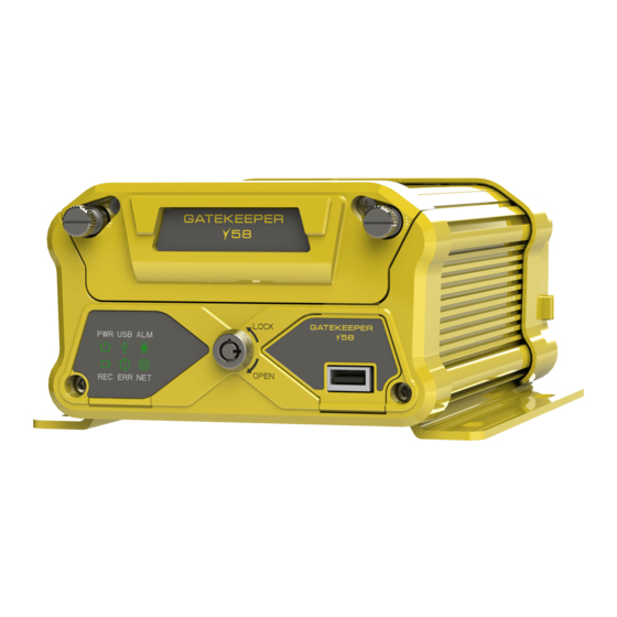
A. Spring Pins: Keeps HD caddy in place. Twist and pull to gain access. B. LED Status Indicators: Status indicator lights which light up and/or flash to alert the user to the device’s operational status and/or alarm status. Figure 2-2 Close Up View of the Y58 Status Indicator Lights 9 of 148... -
Page 10: Back Panel Of Y58
SD Card Door: Y58 supports up to 256GB SD card. To access the SD card slot, turn off the device, then take out the HDD caddy, then open the SD Card Door. - Page 11 User Manual & Install Guide A. Analog and Analog HD camera connectors. B. IP Camera connector. C. WAN connector. D. Sensor Cable (CAB000459) connection. GPS Antenna In: This is the connection point for the external GPS antenna. Serial Cable connection. G.
-
Page 12: Included
Power Cable (CAB000360) This is the vehicle power ignition cable for powering the Y58 and its connected accessories. Serial Cable (CAB000458) Serial Cable to connect the Driver Alert Button. -
Page 13: System Specifications
There are numerous customizable options and accessories which can tailor the product installation to fit your unique operating environment and requirements. Please contact Gatekeeper Systems for information on optional download kits and other accessories for use with your product. 2.3 System Specifications... - Page 14 User Manual & Install Guide CIF-(352x240) HD - NTSC ×480) WD1-(928 WHD1 (928×240) ×240) WCIF (464 (704×240) ×240) (352 Number of Camera Resolution Channels Type 1080P Video Resource 1080P (without a switch) 720P 1080P Number of Camera Resolution Channels Type 1080P Video Resource 1080P...
- Page 15 User Manual & Install Guide 32GB, 64GB, 128GB, 256GB Recording Recording Trigger Recording Trigger Schedule, alarms, sensor triggers Pre-recording 0 to 60 min Post-recording Max 30 min File Size 15 min of video Playback DVR Video Playback 1 channel local up to 8 channels using G4 Viewer Plus Search Method Date/Time, channel file type, event Network...
-
Page 16: Channel Configuration Limitation Matrix
2.5 Hard Disk Drive The Y58 has one caddy that is used for a single HDD or SSD storage. The HDD/SSD storage is up to 4TB. Hard Drives are very simple to use, and very reliable. The Hard Drives supplied by Gatekeeper Systems have been extensively tested and are the only approved Hard Drives for use in the Y58. -
Page 17: Gps
User Manual & Install Guide using the Y58, the Hard Drive is installed via a Removable Hard Disk Drive Caddy. It utilizes a state-of- the-art suspension system and smart thermal management technology to withstand the shocks, vibration and environmental stresses inherent in vehicle operation. Be sure to use the caddy provided with the Y58, or possible damage that could occur to the hardware. -
Page 18: Getting Started
3 Getting Started 3.1 Learning How to Navigate Your Y58 comes with a simple graphical user interface from which you can access all the features and functions. You can select from a choice of intuitive interface devices with which to navigate the system. -
Page 19: Using The Trackball Mouse
3.1.1 Using the Trackball Mouse. The trackball mouse, together with the accompanying LCD monitor, provides one way to access the Y58 menu and functions using a familiar graphical user interface point-and-click system. Figure 3-1 Side View of the Finger Mouse Right Button: When viewing video streams, pressing this button will toggle between showing and hiding the on-screen quick menu. -
Page 20: Using The Interactive Control Display (Icd2)
User Manual & Install Guide How to Connect the Finger Mouse and LCD Monitor Figure 3-2 Connecting the Finger Mouse and LCD Monitor 3.1.2 Using the Interactive Control Display (ICD2) The ICD2 is a full-featured touch display that makes navigating the device menu system very intuitive. Besides the touch function, this accessory also has several buttons that act as hotkeys allowing the user to quickly select and go to different functions. -
Page 21: Figure 3-3 Front View Of The Icd2
User Manual & Install Guide Figure 3-3 Front View of the ICD2 Touch Screen: A single tap anywhere on the screen (when showing video streams) will bring up the on-screen quick menu. Another single tap anywhere on the screen will hide the quick menu again. At all times, tapping on an on-screen field, tab or button in the menu system will select it. -
Page 22: Guide To Common Navigation Actions
How to Connect the ICD2 Figure 3-4 Connecting the ICD2 The Y58 has a dedicated ICD port on the back panel of the DVR (refer to Figure 2.3 Rear View of the Y58). Connect the ICD and the DVR with the CAB000391 extension cable. - Page 23 User Manual & Install Guide Action Finger Mouse ICD2 Entering text into a Move the on-screen pointer Tap on the text field with selected alphanumeric using the Trackball until it your finger. An on-screen field. is situated over the text keyboard will be displayed.
-
Page 24: The Y58 Start-Up Screen Layout
Upon start-up, the screen of the Y58 will display the live video streams from the various cameras attached to the Y58. Users can select and configure how many video channels to be displayed on the screen for monitoring purposes. The screen also serves as an interface into the menu system of the Y58 where users can playback recorded video and access the configuration menu to change the device configuration settings. -
Page 25: Figure 3-5 Y58 Startup Screen
User Manual & Install Guide Figure 3-5 Y58 Startup Screen Live Video from Cameras: By default, upon system start-up, the screen will display live video from the camera attached to channel one in a single-camera full onscreen view. Clicking anywhere on the video screen will bring up the on-screen quick menu where the user can select from several different display options, including Single-Camera On-screen View, Dual Camera On-screen View, Quad Camera On-screen View, and 9 Camera On-screen Views. -
Page 26: Viewing Live Video
User Manual & Install Guide 3.4 Viewing Live Video Single Camera On-screen View When the screen is in Single-Camera On-screen View mode, the camera from a single camera channel will be shown on the entire screen. To select a specific camera for viewing, you may press any of the keys [1-8] on the ICD2 to immediately jump to that channel and display the video stream from the corresponding camera. -
Page 27: Figure 3-7 Example Of Video Loss
User Manual & Install Guide corresponding camera. This will switch the display to Single Camera On-screen View to display the video from the selected camera. Once you have selected a channel to view, you can cycle through the available channels iteratively in quad grid display mode by pressing the key zero [0] on the ICD2. -
Page 28: Quick View Of System Status Information
The information shown is as follows: Device Name Device ID Serial Number MAC Address – this is the Y58 LAN MAC Firmware Version MCU Version ICD Version – this is the ICD firmware 28 of 148... - Page 29 This screen shows a summary of the Location 3. Modules – Location. of the Y58. Location status – defines the physical location of the Y58 using GPS co- ordinates. Location source – defines where the Location is sourced. Location Plant Number – is an internal marker.
- Page 30 5. Server Status port number). Note: These settings are only applicable when the device is set up for a network connection within a Gatekeeper Wireless Configuration. The information shown is as follows: Server Status Network Type Protocol Type...
- Page 31 User Manual & Install Guide 7. Storage This screen lists the storage devices which are currently attached to the device. It also indicates whether the device is currently recording to the listed storage devices, their total storage capacity, as well as remainder capacity in storage space as well as estimated recording time.
-
Page 32: Logging Into The System
3.6 Logging into the System In order to access many of the Y58 advanced functions, you will need to be logged in to the system. This is a security measure to ensure that access to sensitive functions and video data is restricted to authorized users. - Page 33 User Manual & Install Guide How to Log In When attempting to access any of these functions, the system will check the log-on status of the user before granting access to the function. If the user is not already logged in, the system will automatically prompt the user to log in.
-
Page 34: Understanding The Main Menu
Click the (Login) button. If the password is correct, you will be logged in and allowed to access the advanced functions of the Y58 and the Main Menu. At any time, you may also cancel the log-in process by clicking the (Cancel) button. -
Page 35: Figure 3-9 Options In The Main Menu
Logout: Logout the currently logged-in user. This will return the system to the live video view. The REC Search and Log Search functions will be explained in the chapter on Viewing Recorded Data, whilst the Setup function will be explained in the chapter on Configuring the Y58. 35 of 148... -
Page 36: Basic System Quick Start
Turning your vehicle ignition on will automatically power up the Y58. When your vehicle ignition is turned off, the device will automatically shut down after 5 minutes (you will be able to change this later in the device settings). -
Page 37: Step 3: Logging In And Accessing System Configuration
User Manual & Install Guide 4.3 Step 3: Logging in and Accessing System Configuration You may now log into the system and go to the Main Menu where you can access the device Setup and configuration settings. Step 3.1 If you are using a Finger Mouse, click the Right Button, whereas ICD2 users can just tap on the screen. - Page 38 Click on the (Setup) button to go to the device configuration screen. Understanding the Setup Menu System for System Configuration The Y58 comes with a comprehensive setup menu system where you will be able to tailor almost every aspect of the device operations to your unique fleet requirements.
- Page 39 User Manual & Install Guide Alarm – where you will be able to configure recording, snapshot and other actions that the device will perform when an alarm event occurs. For a detailed explanation, please see Section 6.6. Maintenance – where you will be able to perform various maintenance actions, including data export and firmware upgrades.
-
Page 40: Step 4: Setting The Date And Time
User Manual & Install Guide Figure 4-2 Setup Menu System for Device Configuration For the basic setup process, we will just need to verify and/or configure the settings in the subsections highlighted with the red dotted lines in the diagram, as follows: Under the Basic section: Regist Info Time Setup... -
Page 41: Step 5: Setting The Vehicle Identity Information
User Manual & Install Guide DEFAULT SETTINGS: Time and date according to GMT- 8:00 Satellite DEFAULT SETTINGS: Checkbox – Selected Centre Server DEFAULT SETTINGS: Checkbox – Unselected NTP Sync DEFAULT SETTINGS: Checkbox – Unselected DST (Day Light Saving Enable DEFAULT SETTINGS: Time) Checkbox –... -
Page 42: Step 6: Setting Basic Preferences
User Manual & Install Guide Device Info Device ID Leave this value as it is unless directed to change by Gatekeeper Project Team. Vehicle Info Vehicle Plate You can use this field to key in the vehicle registration plate number. -
Page 43: Step 7: Setting Up Authorised Users
4.7 Step 7: Setting Up Authorised Users Next, you can add additional user login accounts to the device if required. Navigate to: Main Menu Setup Basic Setup User Setup Your Y58 comes pre-configured with the following two default user accounts: 43 of 148... - Page 44 Normal User It is highly recommended that you do not change the password on the default administrator account, as this account will be used by authorized Gatekeeper Systems engineers to troubleshoot your device during support and maintenance. You may change the password for the default normal user account, and also add an additional normal user account if required.
-
Page 45: Step 8: Setting Up Recording
User Manual & Install Guide 4.8 Step 8: Setting Up Recording The Y58 is a hybrid DVR. It has the capability of having a combination of 6 Analog; Analog HD, and 2 IP camera connected at the same time. This next step is a crucial step, where you will select which cameras to record video from, and also set up the quality and resolution of the recorded video. - Page 46 User Manual & Install Guide Notes: channel no 7 and 8 are for IP cameras. Enable For channels 1 to 6, only enable the channels which actually have cameras connected. Please note that the system will show a video loss message on channels which are enabled, but do not have a connected camera (i.e., no incoming video stream).
- Page 47 User Manual & Install Guide Note – Click on the “?” to get more information. Storage Dual Stream DEFAULT SETTINGS: Split Disabled SD write Resource Ratio DEFAULT SETTINGS: 0.0% Record Storage DEFAULT SETTINGS: Internal SD Record Mode DEFAULT SETTINGS: Mirror Record Alarm CH DEFAULT SETTINGS: All channels checkbox unselected...
-
Page 48: Step 9: Setting U Pip Cameras
Please follow the steps in Section 6.4.3 to setup the IP Camera in your system. 4.10 Step 10: Finish Your new Y58 system is now setup and ready to go! Please also review Chapter 5 to learn about viewing and clipping the recorded video. -
Page 49: Viewing Recorded Data
User Manual & Install Guide 5 Viewing Recorded Data 5.1 Using the Playback Feature The Playback feature can be accessed from the on-screen quick menu after logging in. It functions as a shortcut which allows the user to immediately access and view recorded video from the start of the current day (beginning 00:00:00H) till the current time of the day. -
Page 50: Figure 5-2 Playback On-Screen Controls
User Manual & Install Guide The Video Playback On-Screen Controls If you are using a Finger Mouse, you can toggle the on-screen controls by pressing the Right Button, whereas with the ICD2, you would just tap anywhere on the video. If there is no user input, then the on- screen playback controls will auto-hide after 15 seconds of inactivity. - Page 51 User Manual & Install Guide Mute Toggle: To mute or unmute the volume of the audio in the video recording currently being played. Reverse Play: Clicking this button will cycle the reverse playback speed iteratively through the following speed settings – 2x, 4x, 8x and 16x. Play / Pause: Clicking this button will toggle the video between playback and pause.
-
Page 52: Using Rec Search
The REC Search feature can be accessed from the Main Menu after logging in. It allows the user to search for and view any recorded video which is stored on the Y58 storage Hard Drive. Users can also select and export video clips of specific time periods to an external storage device (such as USB flash drive) for later viewing. - Page 53 REC Search Step 2: Selecting the Camera Channels In a complex multi-camera configuration such as the Y58 which can have up to 8 connected cameras in total, even a single day may contain a lot of recorded video data. This next step allows you to filter the data by selecting only the camera channels of interest to view.
-
Page 54: Figure 5-4 Rec Search Camera Channel Controls
User Manual & Install Guide Figure 5-4 REC Search Camera Channel Controls Main Menu: Click this icon to return to the Main Menu. Back to the Previous Screen: Click this icon to return to the Previous Screen that you were at. Video Type: Clicking the (v) button displays a drop-down menu which allows you to select the type of video to search for and retrieve. -
Page 55: Figure 5-5 Rec Search Time Controls
User Manual & Install Guide Figure 5-5 REC Search Time Controls Main Menu: Click this icon to return to the Main Menu. Back to the Previous Screen: Click this icon to return to the Previous Screen that you were at. Time Scale: This is the time bar that shows recorded video availability for the day (from 00:00:00H to 23:59:59H). - Page 56 User Manual & Install Guide Playback Start Time: This shows the selected playback time. Clicking on it will bring up the time control dialog which allows you to key in a specific time (in hh:mm:ss 24-hour time format) from which to begin the playback. Playback Start Time Marker: This vertical blue dotted line indicates the playback start time across the camera channels.
-
Page 57: Figure 5-6 Rec Search Playback Controls
User Manual & Install Guide Figure 5-6 REC Search Playback Controls Selected Time Period: This time bar represents the selected time period. Recorded Video Available: The green shaded areas in the time bar lets you easily identify where the recorded video is available. Slider Bar Knob: Using a Finger Mouse or an ICD2, you can click-and-drag this moveable knob to the specific time where you wish to view the recorded video. - Page 58 User Manual & Install Guide Cycle to Next Channel: Switch playback to the next camera channel. For example, if the system is currently playing recorded video from Camera 3, then clicking this button will switch to playing recorded video from Camera 4. Cycle to Previous Channel: Switch playback to the previous camera channel.
- Page 59 Please Note: If you are using the Finger Mouse/LCD combination to navigate you will need to use a Gatekeeper Systems USB Hub to allow two devices to share the one USB port.
- Page 60 Click the (Export) button to proceed. You may also click the (Cancel) button in order to go back and select a different time period. Gatekeeper Systems USB hub. Note the instructions for the correct order in which to connect devices.
-
Page 61: Using Log Search
(such as USB flash drive) for later viewing. Please Note: If you are using the Finger Mouse/LCD combination to navigate you will need to use a Gatekeeper Systems USB Hub to allow two devices to share the one USB port. Log Search Step 1: Selecting the Date The first step in the Log Search screen allows you to select a date to view the associated log files. -
Page 62: Figure 5-7 Log Search Date Controls
User Manual & Install Guide Figure 5-7 Log Search Date Controls Main Menu: Click this icon to return to the Main Menu. Back to the Previous Screen: Click this icon to return to the Previous Screen that you were at. Logs Available: A green bar below the date indicates that log files exist for that particular date. -
Page 63: Figure 5-8 Log Time And Type Selection
User Manual & Install Guide Log Search Step 2: Selecting the Time and Log Type The next step in the Log Search function allows you to select the time period and the type of log that you wish to view. Figure 5-8 Log Time and Type Selection Main Menu: Click this icon to return to the Main Menu. -
Page 64: Figure 5-9 View And Export Log File
User Manual & Install Guide or overwritten by the device. Locked events are events for which the corresponding video is still in locked mode. If the Alarm log type is selected, the log file can be filtered further by Alarm Type. Show all alarm events. -
Page 65: Configuring The Y58
6 Configuring the Y58 6.1 Quick Reference to Configuration Menu System The following shows a high-level map to the various settings in the Y58 configuration menu system. Please refer to the following sections for a detailed description of each section. -
Page 66: Figure 6-1 Layout Of The Configuration Menu
User Manual & Install Guide The configuration menus are presented in a tabular format, where the main sections can be selected from the row of tabs at the top of the screen. The subsections within each main section are arrayed in columnar format, and can be selected from the column of page subsections on the left edge of the screen. - Page 67 If you navigate away from the current page/tab without saving, any changes that you have made to the settings will be discarded. Please note that your configuration settings have been set by Gatekeeper Systems engineers to meet your specific deployment requirements. Do not reset to factory defaults or change the settings unless you fully understand the changes you are making, or as directed by Gatekeeper Systems.
- Page 68 User Manual & Install Guide This is a general field which accepts user input. Clicking the field will display an on-screen full qwerty keyboard for the user to key in the text (both alphabetical and numbers). Text Field However, if the field will only accept numeric values, clicking on the field will display an on-screen keypad for the user to key in numeric values.
-
Page 69: Basic Settings
User Manual & Install Guide This is a controlled input field which only accepts selections from a predefined list of items. This kind of field can be identified by a (˅) button to the right of the field. Clicking this button will display a list of items which can be scrolled and selected. -
Page 70: Regist Info
You may input up to a maximum of: 5 digits Note: This value is only set when the device is configured as part of a Gatekeeper Wireless deployment. DEFAULT SETTINGS: Please refer to Gatekeeper Project Team, in consultation with customer/school district, for the value to set. -
Page 71: Time Setup
User Manual & Install Guide DEFAULT SETTINGS: Gatekeeper Project Team, in consultation with the customer/school district, will determine the value to set. Line Number Alphanumeric text field for setting the vehicle line number. Typically, the identification code used by the fleet operator to identify a route. - Page 72 User Manual & Install Guide The device contains a real-time clock. This subsection enables you to view and set the date and time for the device, and also configure the options used for time synchronization as well as daylight savings. General Date Format Drop-down list which allows you to choose the...
- Page 73 GPS satellites. Note: This is the recommended setting to use when the Y58 is deployed in a mobile environment. To use this setting, the Y58 must be equipped with the GPS option.
- Page 74 User Manual & Install Guide Note: This setting requires a constant network connection either via cellular or Wi-Fi. DEFAULT SETTINGS: Checkbox – Unselected Enable Checkbox – selecting this will enable the device to calculate and adjust for daylight savings time. DEFAULT SETTINGS: Checkbox –...
- Page 75 User Manual & Install Guide If the device is adjusting for daylight savings by Week, you will need to specify the following: Drop-down list to choose the start month (from JAN to DEC). Drop-down list to choose the start week (either 1 or LAST).
-
Page 76: Startup
User Manual & Install Guide 6.3.3 Startup Navigate to: Main Menu Setup Basic Setup Startup This subsection enables you to set the Startup characteristics of the device, as well behaviour of the device whilst in sleep mode. ON/OFF Power UP/Shutdown Drop-down list to select the conditions for Mode device Startup and shutdown:... - Page 77 User Manual & Install Guide Sleep Sleep Mode Drop-down list to select the sleep mode option for the device: No Consumption Standby Low Power Standby Notes: Currently, this is the only option available. DEFAULT SETTINGS: No Consumption Standby This means that the device will not be consuming battery power when it is shut down.
-
Page 78: User Setup
User Manual & Install Guide 6.3.4 User Setup Navigate to: Main Menu Setup Basic Setup User Setup This subsection enables you to add and edit users, as well as change the passwords required to log into the system. User Setup Idle Time Drop-down list which allows you to set the login... -
Page 79: Network
User Manual & Install Guide Alphanumeric text field to key in the user password a second time to confirm it. User name maximum of: 10 characters For password, you may input up to a maximum of: 16 characters Delete After using the checkbox to select a user, this button will allow you to delete the selected user. - Page 80 User Manual & Install Guide DEFAULT SETTINGS: Checkbox – Selected IP Address Numeric text field allowing you to key in the IP address for the device. DEFAULT SETTINGS: 192.168.001.100 Subnet Mask Numeric text field allowing you to key in the IP address subnet mask for the device.
- Page 81 User Manual & Install Guide Alternate DNS Server Numeric text field allowing you to key in the IP address of the alternate DNS server. DEFAULT SETTINGS: 192.168.001.001 Ports WEB Port Numeric text field to set the web port number. DEFAULT SETTINGS: Internal Wi-Fi (FlexFi) Enable Enable/Disable the internal Wi-Fi.
- Page 82 Gateway DEFAULT SETTINGS: Disable NOTE: THE FOLLOWING SECTION (SERVER) IS ONLY APPLICABLE WHEN THE DEVICE IS BEING CONFIGURED AS PART OF A GATEKEEPER WIRELESS DEPLOYMENT. Server Centre Server Drop-down list which displays a list of centre servers configured in the device. Selecting one...
- Page 83 User Manual & Install Guide These configuration values are server specific. If you have more than one centre server set up, you will need to select each in turn and configure them separately. Add – this button allows you to add a new centre server name and configure its settings.
-
Page 84: Application
User Manual & Install Guide Register Server IP Numeric text field to configure the IP address of the register server. DEFAULT SETTINGS: _ _ _ . _ . _ _ . _ _ _ Register Server Port Numeric text field to configure the port values used by the register server for the following protocol types: DEFAULT SETTINGS:... -
Page 85: Surveillance Settings
User Manual & Install Guide ICD2 Volume DEFAULT SETTINGS: Preview Volume DEFAULT SETTINGS: Algorithm ADAS camera Install DEFAULT SETTINGS: Height 153 (cm) 6.4 Surveillance Settings Navigate to: Main Menu Setup Surveillance This section allows the user to setup the Digital IP Camera, and also configure the on-screen display and video capture and streaming settings for both the live viewing as well as the recording functions. - Page 86 User Manual & Install Guide Checkbox – if selected, the audio stream will be played while during Preview Preview the live video view. Else, the audio will be muted by default. Audio Nevertheless, the audio can still be toggled on and off from the video viewing screen itself.
- Page 87 User Manual & Install Guide : Colour Warmth : Colour Saturation Channel Being Configured: This drop-down list enables you to select a channel to configure. The video from the selected channel will be displayed, and you will be able to adjust the settings.
- Page 88 User Manual & Install Guide Please adjust the margins if necessary, to ensure the entire screen fits comfortably within your installed display monitor. DEFAULT SETTINGS: Resolution 1024 ×768 Startup Drop-down list for selecting the type of live video displayed by default Screen after device Startup: Single...
- Page 89 User Manual & Install Guide Auto Loop Screen / Mode This displays a list of screens layouts that have been configured in the / Channel / device. If Auto-Loop is enabled, each of the screen layouts is displayed Duration for the specified duration, and the display will cycle iteratively and Setup repeatedly through the list of screen layouts.
- Page 90 User Manual & Install Guide Add Screen Clicking the (Add Screen) button will add a new screen layout to the list. You can then use the ( ) button to edit the new screen layout settings. Clicking the (x) button will delete the associated screen layout. Auto Loop Checkbox –...
-
Page 91: Record
Surveillance Record The Y58 is a hybrid DVR. It has the capability of having a combination of Analog; Analog HD and a single IP camera connected at the same time. Please Note: The IP camera is a separate device and uses its own settings. Analog HD cameras have a maximum frame rate of 30 Frames Per Second. - Page 92 User Manual & Install Guide Overwrite The device records video cyclically. This drop- down list enables you to specify the conditions whereby older video will be overwritten: By Days – video older than a specified number of days will be overwritten by newer video.
- Page 93 User Manual & Install Guide them will display the currently set configuration values, and allow you to modify them. These configuration values are channel specific. You will need to select each channel in turn and configure them separately. Notes: For quick configuration, the copy function allows you to easily copy the settings of the current channel to another channel.
- Page 94 User Manual & Install Guide HD1 (704x240) WHD1 (928x240) D1 (704x480) WD1 (928x480) 720p (1280x720) 1080p (1920x1080) For the Analog HD cameras (channels 1-6) and Digital IP Camera (channel 7 and channel 8), the drop-down list contents will change to reflect the supported resolutions of the currently attached Analog HD and IP cameras.
- Page 95 User Manual & Install Guide Quality Drop-down list allowing you to select the encoding quality (on a scale of 1 to 8 – where 1 is best). DEFAULT SETTINGS: For all channels, set the following: 1 (Best) Record Mode Drop-down list allowing you to select the record mode: Power Up –...
- Page 96 (jaggedness and blurriness) into the encoded video as the encoder attempts to keep up with quick changing video scenes continuously adjusting the bit rate. For optimal recorded video quality, Gatekeeper Systems recommends the use of the CBR setting throughout. DEFAULT SETTINGS: 96 of 148...
- Page 97 User Manual & Install Guide For all channels, set the following: Audio Coding Format DEFAULT SETTINGS: ADPCM This feature allows you to easily copy the configuration settings on this channel to Copy another selected channel. Use the drop-down list to select a channel – then clicking the (Copy) button will replicate all the current settings to the selected channel.
- Page 98 User Manual & Install Guide Setup Regist Info Vehicle Info Vehicle Plate. DEFAULT SETTINGS: Checkbox – Unselected Channel Name Checkbox – if selected, the channel name will be displayed as an overlay text on top of the recorded video. DEFAULT SETTINGS: Checkbox –...
- Page 99 User Manual & Install Guide Text Data Overlay: The selected data is displayed as a text overlay on top of the video. Moving the Text Data: The position of the text data can be easily customized by moving it to the desired location.
-
Page 100: Ipc Setup
Camera Channels: The available camera channels are listed on the screen along with their associated settings. Please Note: For Y58, there are IP camera channels 7 and 8 (without 4-port switch). Up to a total of 6 IP camera channels with a 4-port switch. -
Page 101: Figure 6-5 4 Ip Camera Settings Configuration Screen
The available IP camera will be displayed in a list together with the default settings for IP address, port and protocol type which have been automatically configured by the Y58. Step 1: Click on the checkbox to select the associated camera. -
Page 102: Collection Settings
User Manual & Install Guide 6.5 Collection Settings Navigate to: Main Menu Setup Collection This section allows the user to configure all the settings related to data collection. This includes event logging from sensor input as well as alarms. The user can also configure the options for automated snapshots from the cameras based on specified triggers. -
Page 103: General
User Manual & Install Guide 6.5.1 General Navigate to: Main Menu Setup Collection General This subsection enables you to view and edit the data collection settings for sensors, alarms, and other related events. Sensor Sensor Number Drop-down list which displays the list of available sensors. - Page 104 User Manual & Install Guide DEFAULT SETTINGS: Sensor Number: 1 Sensor Name – BRAKE OSD Name – BK Sensor Number: 2 Sensor Name – WARNING OSD Name – WN Sensor Number: 3 Sensor Name – STOPARM OSD Name – SA Sensor Number: 4 Sensor Name –...
- Page 105 User Manual & Install Guide External GPS 3Axis Acc DEFAULT SETTINGS: None The second associated drop-down list allows the user to set the baud rate for the port: 4800 9600 19200 38400 56000 57600 115200 DEFAULT SETTINGS: 4800 232-2 First Drop-down list: DEFAULT SETTINGS: None Second Drop-down list:...
- Page 106 User Manual & Install Guide system is adopted will typically choose KM/H. DEFAULT SETTINGS: Source Drop-down list allowing the user to set the source for the speed measurement: Satellite Pulse Notes: If the measurement unit is set to Pulse, you will also need to select the calibration mode and perform a manual calibration.
-
Page 107: Snap Setting
Enable – if the checkbox is selected, then this camera channel is included when the Y58 performs the snapshot task. Resolution – this drop-down list enables you to select the resolution for the snapshots. - Page 108 Enable – if the checkbox is selected, then this camera channel is included when the Y58 performs the snapshots. 108 of 148...
- Page 109 Enable – if the checkbox is selected, then this camera channel is included when the Y58 performs the snapshots. 109 of 148...
-
Page 110: Eco-Driving
User Manual & Install Guide Resolution – this drop-down list enables you to select the resolution for the snapshots. Available options are (CIF, WCIF, HD1, WHD1, D1, WD1, 720P). Quality – this drop-down list enables you to select the quality of the snapshot on a scale of 1 to 8 (where 1 is best). -
Page 111: Alarm Settings
User Manual & Install Guide Total Oil Base DEFAULT SETTINGS: Coefficient Mileage DEFAULT SETTINGS: Coefficient Oil DEFAULT SETTINGS: GDS Work Pattern DEFAULT SETTINGS: Normal Clear Statistical DEFAULT SETTINGS: Clear Maintenance Threshold Temperature Temperature DEFAULT SETTING: Checkbox – unselected Voltage Default Settings: Checkbox –... -
Page 112: Base
User Manual & Install Guide 6.5.4 Base Navigate to: Main Menu Setup Alarm Base This subsection enables you to set up the trigger for alarm events based on speed, panel and IO input, and to define the actions that will be taken when the alarm occurs. Speed Alarm Overspeed / Enable Checkbox –... - Page 113 User Manual & Install Guide Early Difference: Numeric field to key in a value for when the vehicle goes over a specified speed prior to the actual speed limit. Speed: Numeric field to key in the speed value over which the device will flag an over speed alarm.
- Page 114 User Manual & Install Guide If Single (1x1), Dual (2x1) or Quad (2x2) display is selected, the (Setup) button allows you to select the layout of the channels to be displayed on-screen. The drop-down lists are shown on- screen according to the grid layout mode selected.
- Page 115 User Manual & Install Guide Press Duration: Numeric text field to key in the duration of the panic button press on the panel for which the device will flag the panic alarm. Save Settings: Click the (OK) button to save the alarm settings. Back to Previous: Click the (Cancel) button to return to the previous screen without saving.
- Page 116 User Manual & Install Guide Linkage Screen – drop-down list to select the options to display the video from the selected cameras on-screen when the alarm occurs. None : Not displayed Single : Display 1 camera. Dual : Display 2 cameras. Quad : Display 4 cameras.
- Page 117 User Manual & Install Guide Enable Checkbox – if selected, will enable the device to monitor the associated IO input line for an alarm trigger. DEFAULT SETTINGS: BRAKE – Checkbox – Selected WARNING – Checkbox – Selected STOPARM – Checkbox – Selected DOOR –...
- Page 118 User Manual & Install Guide Channel – checkboxes which allow you to select any combination of the camera channels to be included in the display and recording. Post Recording – numeric value box which allows you to enter the duration for which video will continue to be recorded when the alarm is triggered.
-
Page 119: Driver Alert Button: Setup
6.5.5 Driver Alert Button: Setup A Driver Alert Button is available as an optional accessory for the Y58. The Driver Alert Button must be installed using the provide Tek screws. The Driver Alert allows for the driver of the vehicle to press the button and mark the recorded video with an Alert. - Page 120 User Manual & Install Guide Video Videoloss Checkbox – if selected, enables the device to monitor for videoloss events. In the case of videoloss detected on the specified camera channels, this alarm will be triggered. DEFAULT SETTINGS: Checkbox – Selected Alarm Drop-down list to select the classification level for the alarm: Type...
- Page 121 User Manual & Install Guide grid segments, then those segments associated with an actual camera will be displayed as a black box. Alarm Image Upload – checkbox, if selected will enable the device to upload the alarm to the centre server. Motion Name Set to Motion.
- Page 122 User Manual & Install Guide Tampering Name/Enable DEFAULT SETTINGS: Checkbox – Unselected Alarm Type DEFAULT SETTINGS: Alarm Trigger High Temp. Thresh DEFAULT SETTINGS: 284° F Temp. Increase Warn Time DEFAULT SETTINGS: 10 Minutes Temp. Increase Difference DEFAULT SETTINGS: 154° F Debounce Time –...
- Page 123 User Manual & Install Guide Channel – checkboxes that allow you to select any combination of the camera channels to be included in the display and recording. Post Recording – numeric value box which allows you to enter the duration for which video will continue to be recorded when the alarm is triggered.
-
Page 124: Advanced
User Manual & Install Guide 6.5.7 Advanced Navigate to: Main Menu Setup Alarm Advanced This subsection enables you to set up the trigger for alarm events based on G Sensor input, and also to define the actions that will be taken when the alarm occurs. G-Force Name Checkbox –... - Page 125 User Manual & Install Guide will continue to be recorded when the alarm is triggered. Lock – checkbox, if selected will mark the recorded video associated with this alarm as a locked video. Linkage IO Output – checkboxes, if enabled, the device will send a signal to the selected IO output lines.
- Page 126 User Manual & Install Guide Section Limit Speed DEFAULT SETTINGS: TTS Switch Checkbox – unselected T&H Sensor Name T-Sensor1, name of the Sensor. Enable DEFAULT SETTINGS: Checkbox – unselected Alarm Type DEFAULT SETTINGS: Alarm Trigger High Temp. Thresh DEFAULT SETTINGS: 284°...
-
Page 127: Maintenance Settings
User Manual & Install Guide Output Delay Time – numeric text field to set the delay time for the IO output (in seconds). Linkage Screen – drop-down list to select the options to display the video from the selected cameras on-screen when the alarm occurs. None : Not displayed Single... -
Page 128: Config
This subsection enables you to import and export configuration files for easy configuration of multiple Y58. Please Note: If you are using the Finger Mouse/LCD combination to navigate you will need to use a Gatekeeper Systems USB Hub to allow two devices to share the one USB port. Config Config File Export Click the (Export) button to export the entire device configuration settings to a file. -
Page 129: Filedata
This subsection enables you to export the device data files for viewing and archival. Please Note: If you are using the Finger Mouse/LCD combination to navigate you will need to use a Gatekeeper Systems USB Hub to allow two devices to share the one USB port. Data Export... -
Page 130: Upgrade
This subsection enables you to upgrade the firmware for selected system components. Please Note: If you are using the Finger Mouse/LCD combination to navigate you will need to use a Gatekeeper Systems USB Hub to allow two devices to share the one USB port. Upgrade... -
Page 131: Storage
Navigate to: Main Menu Setup Maintenance Storage This subsection enables you to view and format the storage devices attached to the Y58. Storage Storage Type This shows the various storage devices which are attached to the Y58. Available storage devices shown may include any combination of Hard Drives and/or USB flash drives. - Page 132 User Manual & Install Guide System Reboot Click the (Reboot) button in order to reboot the device. 132 of 148...
-
Page 133: Special Topics
IP Camera needs to be configured in the system with the appropriate settings and IP address before it will work. In the Y58 though, adding a new IP camera to the system can easily be done through the automated setup options available in the setup menu. -
Page 134: Configuring Substream Recording Quality
User Manual & Install Guide Click on the ( ) icon which is on the same row as channel 7 and 8 to add the new IP Camera. More information is listed in section 6.4.3. Step 7.1.1.2 Your new IP Camera’s IP address will now be added to the list on the channel which you had previously selected when you performed the search. -
Page 135: Figure 7-2 Substream Recording Settings
User Manual & Install Guide Figure 7-2 Substream Recording Settings This Substream recording settings configuration needs to be done for each individual camera channel separately. The following options will be available for configuration: Choose Channel – drop-down list to select the particular channel to configure. When a channel is selected, the corresponding recording settings for that channel will be displayed for viewing and editing. -
Page 136: Using A New Hard Drive
User Manual & Install Guide 7.3 Using a New Hard Drive The Y58 uses a propriety file system format to store data to the Hard Drive. As such, any new Hard Drive would need to be formatted in the device itself prior to use. -
Page 137: Upgrading Device Firmware
Please Note: If you are using the Finger Mouse/LCD combination to navigate you will need to use a Gatekeeper Systems USB Hub to allow two devices to share the one USB port. Please follow the insertion process noted on the Gatekeeper Systems USB hub. -
Page 138: Maintenance And Troubleshooting
8 Maintenance and Troubleshooting Maintenance Whilst the Y58 is a dependable and robust piece of equipment, it is still a complex electronic device and as such, will require maintenance occasionally. To ensure optimal performance, Gatekeeper Systems strongly recommends that a proper Preventive Maintenance Schedule be set up and adhered to. -
Page 139: Hardware Installation
DO NOT disassemble the device. There are no user-serviceable parts inside. Configuration Guidelines The device firmware must be configured before using the Y58. Use an ICD2, G4 Connect, Monitor/Finger Mouse combination to access the setup menu. Enter the following login information when prompted:... - Page 140 Please note: non-Gatekeeper branded Hard Drive may not function reliably. If used, non- Gatekeeper branded Hard Drive must be formatted in the Y58 prior to use. Start the vehicle, and wait for the recorder to boot up (approximately two minutes). Confirm live camera video is visible on the monitor (small Green camera in each camera image –...
-
Page 141: Instructions For Mounting The System
Failure to use provided Split Loom and Grommets will void the warranty. Gatekeeper Systems provides Tek Screws with which to mount the Y58 – these have been tested and are approved for mounting. Power Connection Plug the power cable into the DC6-36V connector. - Page 142 User Manual & Install Guide (A) (Black) Connect to the negative terminal of the battery, -12V. Typically, grounds are established in the fuse panel, and installers would need to connect there. IGNITION (B) (Yellow) Connect to the vehicle ignition, +12V, the signal required to activate the device.
-
Page 143: Detailed Cabling Diagrams
9.3.1 Fuse Connections Figure 9-1 Y58 Fuse Connections 9.3.2 Cabling Diagrams Please refer to the following pages with detailed cabling diagrams for the different installation configurations of the Y58. Figure 9-2: Y58 Wiring with MWM (Mobile Wireless Module) 143 of 148... -
Page 144: Camera Mounting And Connections
The audio hole on the front of the camera can be used as an aiming guide for the direction the camera needs to be facing. All camera harnesses must be carefully routed to the Y58 unit to avoid pinching or piercing the shielded camera cable. - Page 145 Step 7 To aim the Camera Ball (C), video from the camera can be viewed by connecting a portable LCD/Monitor with an RCA connection to the front of the Y58, or, by use of the ICD2 accessory available from Gatekeeper Systems.
- Page 146 User Manual & Install Guide Suggested Camera Mounting Locations Check For: Ceiling mount recommended. Do not obstruct walkways. Avoid contact with abrasive metal to prevent short circuits. Wire Routing: Camera harness to be connected through an opening in the base. Use existing wire paths wherever possible, e.g.
-
Page 147: Customer Limited Warranty
INCIDENTAL, CONSEQUENTIAL OR OTHER DAMAGES INCLUDING, of the product. Y58 must be returned once every twelve months for BUT NOT LIMITED TO THE EXPENSE OF RETURNING THE service otherwise warranty may be void. -
Page 148: Contact Information
User Manual & Install Guide 11 Contact Information. CONTACT INFORMATION GSI – Canada 301-31127 Wheel Avenue Abbotsford, BC V2T 6H1 Canada GSI – USA Unit 82A - 446 Harrison Street Sumas, WA 98295 SALES & TECHNICAL SUPPORT North America: Tel: 1.604.864.6187 Fax: 1.604.864.8472 Toll Free: 1.888.666.4833 148 of 148...
Need help?
Do you have a question about the Y58 and is the answer not in the manual?
Questions and answers