
Related Manuals for Otto Bock Invader 480S26 10000 K


Summary of Contents for Otto Bock Invader 480S26 10000 K
- Page 1 Invader 480S26=10000_K Instructions for use ....................
- Page 2 Invader 480S26=10000_K...
-
Page 3: Table Of Contents
Table of contents Table of contents Foreword ................................Product description ............................Function .............................. Product overview ..........................Intended use ................................ Indications for use ..........................Indications ............................Contraindications ..........................3.3.1 Absolute Contraindications ........................3.3.2 Relative Contraindications ........................Qualification ............................Safety ..................................Explanation of warning symbols ...................... - Page 4 Table of contents Seat and back upholstery ........................9.4.1 Removing and fastening the seat cushion ....................9.4.2 Removing and fastening the back support pad ..................Backrest ............................9.5.1 Folding down the back support (option) ....................9.5.2 Flexible back tube end (option) ......................
-
Page 5: Foreword
Foreword 1 Foreword INFORMATION Date of last update: 2020-03-19 ► Please read this document carefully before using the product and observe the safety notices. ► Instruct the user in the safe use of the product. ► Please contact the manufacturer if you have questions about the product or in case of problems. ►... -
Page 6: Product Overview
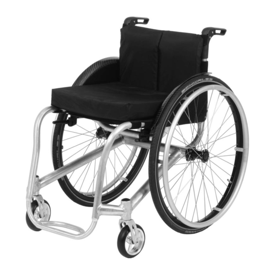
Product description 2.2 Product overview Invader 1 Push handle 7 Leg support 2 Back support with back support upholstery 8 Caster wheel 3 Side panel 9 Quick-release axle 4 Seat upholstery/seat cushion 10 Drive wheel 5 Scissor wheel lock 11 Handrim 6 Frame Invader 480S26=10000_K... - Page 7 Product description Invader Heavy Duty 1 Push handle 7 Foot plate 2 Back support with back support upholstery 8 Caster wheel 3 Side panel 9 Quick-release axle 4 Seat upholstery/seat cushion 10 Drive wheel for drum brake 5 Knee lever wheel lock 11 Handrim 6 Frame 12 Drum brake lever...
-
Page 8: Intended Use
Intended use 3 Intended use The safe use of the product can only be ensured in case of intended use in accordance with the information con tained in these instructions for use. The user is ultimately responsible for accident-free operation. 3.1 Indications for use The wheelchair is intended for everyday indoor and outdoor use, by the user or an attendant, of people with tem... -
Page 9: Safety Instructions For Use
Safety 4.3 Safety instructions for use Hazards during preparation for use WARNING Independent modification of settings Serious injuries to the user due to improper changes to the product ► Do not modify the settings established by the qualified personnel. Only the settings described in the section “Use”... - Page 10 Safety CAUTION Risky operation Falling, tipping over backwards due to approaching obstacles incorrectly ► Push slowly when crossing obstacles (e.g. steps, curbs) and negotiating uphill or downhill slopes and inclines. ► Never cross obstacles at an angle. Always approach obstacles head on (at an angle of 90°). ►...
- Page 11 Safety Hazard in case of broken skin CAUTION Skin damage Skin damage or pressure points due to overloading ► Check your skin for intactness before and during use of the product. ► Pay attention to diligent skin care and pressure redistribution during interruptions in using the product. ►...
-
Page 12: Side Effects
Delivery NOTICE Use under incorrect environmental conditions Damage to product due to corrosion or abrasion ► Do not use the product in salt water. ► Make sure that the wheel bearings are not damaged by sand or other particles. 4.4 Side effects The following side effects may occur during use of the product: •... -
Page 13: Options
Preparing the product for use 5.2 Options The standard model can be fitted to the user's personal requirements thanks to a large range of options. For use of these options: see Page 22 ff. 5.3 Storage 5.3.1 Storage during daily use The product should always be stored so it is protected against external influences. -
Page 14: Settings And Assembly Instructions
Settings and assembly instructions 7 Settings and assembly instructions 7.1 Prerequisites WARNING Making incorrect adjustments Tipping over, falling or malposition of the user due to incorrect adjustments ► Adjustment and assembly work may be carried out only by qualified personnel. ►... -
Page 15: Adjusting The Drive Wheels
Settings and assembly instructions 7.3 Adjusting the drive wheels 7.3.1 Adjusting the quick-release axle The quick-release axle should be set so the wheel is correctly engaged, with no play on the axle. 1) Hold the quick-release axle by the head (wrench size: 19 mm) and by the tip (wrench size: 11 mm) with a ring and open-ended wrench respectively. -
Page 16: Adjusting The Caster Wheels
Settings and assembly instructions 7.4 Adjusting the caster wheels With this wheelchair type, the caster wheel position and caster wheel journal angle cannot be adjusted. 7.4.1 Replacing the caster wheels The caster wheels can be replaced in case of wear. 1) Loosen the caster wheel axle screw connection (see fig. 9, item 1). -
Page 17: Adjusting The Scissor Wheel Locks
Settings and assembly instructions 5 mm 7.5.2 Adjusting the scissor wheel locks 1) Loosen the Allen head screws in the clamp brackets (see fig. 14, item 1). 2) Adjust/move the support for the scissor wheel lock to any position in the clamp bracket (see fig. 14, item 2). If necessary: Slide and twist the clamp bracket on the seat tube. -
Page 18: Adjusting The Back Support Upholstery / Seat Upholstery
Settings and assembly instructions 7.6 Adjusting the back support upholstery / seat upholstery 7.6.1 Adjusting the back support upholstery INFORMATION A well-adjusted backrest provides lasting comfort for the wheelchair user and reduces the risk of secondary dam age and pressure zones. Do not create too much pressure. INFORMATION Ensure that the user's pelvis is positioned as far back in the wheelchair as possible, i.e. -
Page 19: Adjusting The Leg Supports
Settings and assembly instructions Invader Wave On this version, the seat straps are threaded through metal loops on the frame tube. The adjustment is as described above. Please note: This version has two-piece seat straps (hook-and-loop version). A short strap (hook/hook version) is attached in addition on the loop surface of the seat straps in the area between the seat tubes. -
Page 20: Adjusting The Support Angle
Settings and assembly instructions Version with seat clamp (Invader Wave only) 1) Slightly loosen the Allen head screws on the seat clamps (see fig. 24, item 1). 2) Adjust the lower leg length (continuously adjustable). Ensure that the foot plate bar is inserted into the frame tube by at least 40 mm. -
Page 21: Adjusting The Anti-Tipper
Settings and assembly instructions 7.8 Adjusting the anti-tipper CAUTION Incorrect installation of the anti-tipper Tipping over, falling of the user due to incorrect adjustment ► Verify that the anti-tipper has been installed and adjusted properly. Find the appropriate position with the assistance of a helper. -
Page 22: Adjusting The Lap Belt
Delivery 7.9 Adjusting the lap belt CAUTION Incorrect approach to the adjustment process Injuries, malpositions, user discomfort due to adjustment errors ► The qualified personnel is responsible for the individual positioning and fitting of the belt system. ► Adjusting the belt system too tightly may lead to unnecessary pain or user discomfort. ►... -
Page 23: Getting In And Transferring
The recommended overall width for manual wheelchairs in an operational state is 700 mm. This specification • should ensure unhindered use of escape routes, for example. Please note that the product dimensions can exceed the recommended value in versions with very large seat widths (for more information see see Page 43 ff.). -
Page 24: Removing And Fastening The Calf Strap
9.3.1 Removing and fastening the calf strap The calf strap offers additional support for the user's legs (see fig. 31). It can be removed for cleaning. Fastening the calf strap 1) Open all hook-and-loop closures. 2) Loop the calf strap around the frame tubes (see fig. 32). 3) Adjust the length and fasten the hook-and-loop closure. -
Page 25: Removing And Fastening The Seat Cushion
9.4.1 Removing and fastening the seat cushion The seat cushion can be removed for cleaning. 1) Remove the seat cushion from the seat pad (see fig. 33). 2) After cleaning (see Page 37): Place the seat cushion on the seat pad. The seat cushion is secured against sliding by being pressed on to the hook-and-loop fastener. -
Page 26: Backrest
9.5 Backrest The product can be equipped with a permanently welded or optionally a folding backrest. The back support can be equipped with a fixed back plate as an alternative to back support upholstery. 9.5.1 Folding down the back support (option) CAUTION Exposed pinch points Crushing, pinching due to incorrect handling... -
Page 27: Side Panels
3) Adjust the inner bolt with the desired flexibility. 4) Reinstall the back tube end. 5) If necessary: Reattach the leather corners with hook-and-loop fasteners (see fig. 69). 9.6 Side panels CAUTION Pinching at the side panels Pinching, crushing due to lack of caution in danger areas ►... -
Page 28: Adjusting The Height Of The Push Handles
2) Fold the push handle down by 90° (see fig. 44). CAUTION! Make sure the fingers are not pinched between the push handle and back support. Unfolding the push handles 1) Fold the push handle up by 90° (see fig. 44). 2) When the active pushing position is reached, you can hear the push handle engage. 9.7.2 Adjusting the height of the push handles The height of the telescoping push handles can be adjusted in order to make pushing easier for the attendant. -
Page 29: Removing And Mounting The Drive Wheels
CAUTION Reaching into exposed drive parts Crushing, pinching due to incorrect handling ► Do not reach between the drive wheel and wheel lock or drive wheel and side panel when driving the product. ► Do not reach into the spokes of the rotating drive wheel while riding in the product. CAUTION Heat development when braking with handrims Burns due to insufficient hand protection... -
Page 30: Caster Wheels And Caster Forks
Drive wheels with lock-release assist The quick-release axle with lock-release assist for people with quadriplegia makes it possible to install the drive wheels even in case of severely limited mobility of the arms and hands. 1) Open the lock-release assist according to the handle position (see fig. 50: locked – handle is parallel to wheel hub;... -
Page 31: Approach In Case Of Stiffness
The combination of caster wheels and caster forks ensures the ability to hold a straight line and navigate bends securely. The caster wheels (Ø 3" – 6") and caster forks were installed by qualified personnel according to the order. 9.9.1 Approach in case of stiffness In case of stiffness, the caster wheel axles should be cleaned and oiled. -
Page 32: Anti-Tipper
Activating/deactivating the knee lever wheel lock 1) Push the handle of the knee lever wheel lock forward (see fig. 55). → The wheel lock bolt secures the wheel. 2) Pull the wheel lock lever upwards (see fig. 11). → The wheel lock lever releases the wheel. 5 mm Activating/deactivating the scissor wheel lock ►... -
Page 33: Activating And Deactivating The Anti-Tipper
WARNING Incorrectly adjusted anti-tipper Risk of falling as a result of incorrectly adjusted anti-tipper. ► The anti-tipper may only be adjusted by qualified personnel. The anti-tipper prevents the wheelchair from tipping backwards when overcoming obstacles and going uphill. The anti-tipper is set for a maximum ground clearance of 50 mm and so that the anti-tipper rollers, as a minimum, project fully beyond the largest diameter of the drive wheels. -
Page 34: Wheelbase Extension
9.12 Wheelbase extension WARNING Inactive wheel lock after adjustment of rear wheels Risk of falling or collision due to lack of brake functionality of the wheel lock ► If the rear wheels are used in combination with a double axle, there is no braking function available when the rear wheels are moved to the rear axle. -
Page 35: Protective Pads (Option)
Information about subsequent acquisition and mounting is provided by the qualified personnel that handed over the product. Using the lap belt 1) Open the buckle. 2) Place the user in an upright, 90° seated position (if physiologically possible). Ensure that the back is up against the back support pad (if physiologically possible). -
Page 36: Removing/Installing The Protective Pads
9.14.1 Removing/installing the protective pads The protective pads can be removed for cleaning. 1) Open the hook-and-loop closures and remove the protective pads (illustration see previous section). 2) After cleaning (see Page 37): Secure the protective pads on the wheelchair again, respectively with the hook-and-loop fasteners to prevent slipping. -
Page 37: Use In Vehicles For Transporting Persons With Reduced Mobility
9.17 Use in vehicles for transporting persons with reduced mobility WARNING Improper use in vehicles for transporting persons with reduced mobility Risk of serious injury when using the product as a seat ► The product has not been approved by the manufacturer for use as a seat in vehicles for transporting persons with reduced mobility. -
Page 38: Cleaning Belts/Straps
Maintenance and repair 9.18.1.3 Cleaning belts/straps Cleaning a belt system with metal closure INFORMATION Observe the washing recommendations on the product and the information in the corresponding instructions for use provided for the product. Straps with metal closures may not be washed in the washing machine as the penetration of water could •... -
Page 39: Maintenance Intervals
Maintenance and repair 10.1.1 Maintenance intervals The functions described below must be checked by the user or an attendant at the specified intervals: When Inspection task Comments Before each use Verify proper functioning of the Operate the wheel lock lever to the stop. brake system The braked wheels are not permitted to turn anymore under operating conditions. -
Page 40: Repair
Maintenance and repair • Under more severe conditions – e.g. in case of increased strain – the user should have an interim inspection of the wheel locks, frame and chassis performed. • Product inspections may only be carried out by qualified personnel. Inspection task Check off after completion... -
Page 41: Inner Tube, Rim Tape And Tyre Replacement
Maintenance and repair 10.3.1 Inner tube, rim tape and tyre replacement CAUTION Improper tyre replacement Injuries to the user due to incorrect installation, product damage ► No person is permitted to sit in the wheelchair during tyre replacement ► Before removing a wheel, support the product so it cannot tip over. ►... -
Page 42: Disposal
Disposal Inflating the tube 1) Ensure that the valve is positioned perpendicularly for proper positioning of the tube and tyre in the region of the valve. 2) Firmly screw on the valve nut. 3) Inflate the tube so that the tyre can still be pressed in easily with your thumb. INFORMATION: If the circumferential lines on the two sides of the tyre are both at an even distance from the rim, the tyre is centred. -
Page 43: Warranty
Technical data 12.2 Warranty Further information on the warranty terms and conditions can be obtained from the qualified personnel that has fit ted this product or the manufacturer's service (see inside back cover for addresses). 12.3 Service life Expected lifetime: 4 years The design, manufacturing and requirements for the intended use of the product are based on the expected life... -
Page 44: Appendices
Appendices Temperatures and relative humidity Transport and storage temperature [°C (°F)] -10 to +40 (14 to 104) Relative humidity [%] 45 to 85; non-condensing 14 Appendices 14.1 Threshold values for wheelchairs transportable by train INFORMATION ► The products in this series fully satisfy the minimum technical requirements of regulation (EU) No. 1300/2014 regarding train accessibility for people with disabilities. - Page 45 Invader 480S26=10000_K...
- Page 46 Invader 480S26=10000_K...
- Page 47 · www.ottobock.de 143441 Moscow Region/Krasnogorskiy Rayon info@ottobock.com.co · www.ottobock.com.co Russian Federation Otto Bock Healthcare Products GmbH Otto Bock de Mexico S.A. de C.V. T +7 495 564 8360 · F +7 495 564 8363 Brehmstraße 16 · 1110 Wien · Austria Prolongación Calle 18 No. 178-A info@ottobock.ru · www.ottobock.ru F +43 1 5267985...
- Page 48 Ihr Fachhändler | Your specialist dealer Otto Bock Mobility Solutions GmbH Lindenstraße 13 · 07426 Königsee/Germany www.ottobock.com...
Need help?
Do you have a question about the Invader 480S26 10000 K and is the answer not in the manual?
Questions and answers