Table of Contents
Advertisement
Quick Links
Advertisement
Table of Contents

Subscribe to Our Youtube Channel
Related Manuals for Keyestudio 4DOF


Summary of Contents for Keyestudio 4DOF
- Page 1 Keyestudio 4DOF Robot Arm Kit for Arduino DIY...
-
Page 2: Table Of Contents
(1) Installing Arduino IDE ......... 73 (2) Installing Driver of V4.0 Board ......74 (3) Arduino IDE Setting ..........79 Project 2: 4DOF Rotation and Pin Control ...... 85 1) Joint Rotation and Servo Angle Settings ..... 85 2) Pin Control ............86 Project 3: Control the Robot Arm by Joysticks ....87... - Page 3 Bluetooth Controls the Robotic Arm ..... 168 Project 5: PS2-controlled Robot Arm (Extension) ..179 5.1 PS2 Joypad Key Test ......... 179 5.2 PS2 Joypad Control .......... 189 5.3 PS2 Controlling Posture Memory ..... 205 5.4 PS2 Controls Posture Memory and Loop ..225...
-
Page 4: Overview
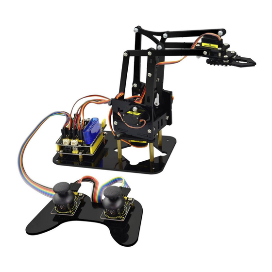
Therefore, we Keyestudio R&D group rolls out an amazing 4DOF mechanical arm kit, which contributes to improving kids’ hand-on ability, logical thinking and observation ability. It is easy to build to say the least. In fact, the four servos of this... -
Page 5: Features
robot arm are controlled by V4.0 control board and two joystick modules. What ’ s more, the detailed tutorials are provided for you even you are a starter. For this mechanical robot arm, there are three methods to control. The first one is controller handle we provide( joystick modules), the second one is App;... - Page 6 The parameters of keyestudio servo motor/ drive shield are as follows: VIN voltage: VIN = DC 7-15V VIN current: 5A Two-channl 5V output: 5V/3A PS2 interface: compatible with Sony PS2 receiver, can be plugged directly into the expansion board.
-
Page 7: Kit List
Note: Peel the plastic film off the board first when you install robotic arm. Picture Item Keyestudio V4.0 Control Board Keyestudio Servo Motor Driver Shield Acrylic Boards... - Page 8 Acrylic Handle MeArm ABS Cylindrical Holder 180° Black Servo BT-24 Module Keyestudio Joystick Module 3D PS2 Joystick Cap...
- Page 9 3*40MM Screwdriver Galvanized Wrench M3*6MM Round Head Screws M3*10MM Round Head Screws M3*14MM Flat Head Screws M3*12MM Round Head Screws M3*24+6MM Copper Pillar M3*6mm+6m Copper Pillar...
- Page 10 M3 Stainless Steel Hex Nuts M3 Hexagon Nuts M1.2x5MM Phillips Self-tapping Screws M2x5MM Phillips Self-tapping Screws M3 304 Stainless Steel Flat Washer M2x8MM Phillips Self-tapping Screws M3*16MM Flat Head Screws Male-Female 10CM Jumper Wire...
- Page 11 Female- Female 50CM Jumper Wire Black 3*100MM Cable Ties 18650 2-Slot Battery Holder...
-
Page 12: Assembly Guide
4. Assembly Guide (1) Install the base of the robotic arm Components Needed:... - Page 16 The base is installed successfully.
-
Page 17: Mount Servos Onto The Base
(2) Mount servos onto the base Components Needed:... - Page 19 Assemble a servo(left) onto the left board...
- Page 20 Components Needed:...
- Page 21 Initialize the left servo Attach this left servo to G, V and S(6)of servo motor driver shield, upload the following code, plug in power and press the rest button on the V4.0 board. Then the left servo rotates to 180° Test Code:...
- Page 22 #include <Servo.h> Servo myservo; // create servo object to control a servo void setup() Serial.begin(9600); delay(1000); void loop() myservo.attach(6); // Change pin to adjust one by one myservo.write(180); //Angle delay(1000); ****************************************************************...
- Page 24 a. Fix the arm:...
- Page 26 Mount a servo(right) onto the right board Components Needed...
- Page 27 Note the breach direction of acrylic board...
- Page 28 b. Initialize the right servo Attach this left servo to G, V and S(A0)of servo motor driver shield, upload the following code, plug in power and press the rest button on the V4.0 board. Then the left servo rotates to 0° Set the servo to 0°:...
- Page 29 void setup() Serial.begin(9600); delay(1000); void loop() myservo.attach(A0); // Change pin to adjust one by one myservo.write(0); //Angle delay(1000); ****************************************************************...
- Page 32 Install the holder part...
- Page 33 Fix the left part and the mount part together...
- Page 35 Fix the right part and the ABS holder together...
- Page 36 Note the direction of the ABS holder...
- Page 40 Install the middle part...
- Page 47 Assemble the claw...
- Page 52 c. Initialize the servo Attach this left servo to G, V and S(9)of servo motor driver shield, upload the following code, plug in power and press the rest button on the V4.0 board. Then the left servo rotates to 0°...
- Page 53 Set the servo to 0°: **************************************************************** #include <Servo.h> Servo myservo; // create servo object to control a servo void setup() Serial.begin(9600); delay(1000); void loop()
- Page 54 myservo.attach(9); // Change pin to adjust one by one myservo.write(0); //Angle delay(1000); **************************************************************** *********** Mount gear wheels:...
- Page 56 Components Needed:...
- Page 58 Initialize the servo Attach this left servo to G, V and S(A1)of sevro motor driver shield, upload the following code, plug in power and press the rest button on the V4.0 board. Then the left servo rotates to 80°...
- Page 59 Set the servo to 80°: **************************************************************** #include <Servo.h> Servo myservo; // create servo object to control a servo void setup() Serial.begin(9600); delay(1000); void loop()
- Page 60 myservo.attach(A1); // Change pin to adjust one by one myservo.write(80); //Angle delay(1000); **************************************************************** Install the robotic arm:...
- Page 62 Mount the control part...
- Page 64 Wiring-up Guide...
-
Page 69: Robot Arm Projects
5. Robot Arm Projects Project 1: Install Arduino IDE and Driver Keyestudio V4.0 Development Board... - Page 70 Keyestudio V4.0 development board is an Arduino uno-comp atible board, which is based on ATmega328P MCU, and with a cp2102 Chip as a UART-to-USB converter.
- Page 71 the AVR, an Arduino micro-program header consisting of MOSI, MISO, SCK, RESET, ICSP VCC, and GND. (In-Circuit It is often called the SPI (serial peripheral interface) and can be considered an Serial "extension" of the output. In fact, slave the Programmi output devices to the SPI bus host.
- Page 72 Arduino MEGA has 14 digital input/output pins (of which 6 can be used as PWM outputs).These pins can be configured as digital input pin to read the logic value (0 or Digital I/O 1). Or used as digital output pin to drive different modules like LED, relay, etc.
- Page 73 Arduino board can be powered via USB connector. All you needed to do is connecting the USB Connection port to PC using a USB cable. USB serial chip, translate the USB signal of CP2102 computer into serial signal Onboard you can find the label: TX (transmit) When Arduino board communicates via TX LED...
- Page 74 To control the voltage provided to the Arduino board, as well as to stabilize the DC voltage used by the processor and other Voltage components. Convert an external input DC7-12V voltage Regulator into DC 5V, then switch DC 5V to the processor and other components.
- Page 75 This pin on the board provides the voltage reference with which the microcontroller operates. A properly configured shield can IOREF read the IOREF pin voltage and select the appropriate power source or enable voltage translators on the outputs for working with the 5V or 3.3V.
-
Page 76: Installing Arduino Ide
(1) Installing Arduino IDE When we get control board, we need to download Arduino IDE and driver firstly. You could download Arduino IDE from the official website: https://www.arduino.cc/, click the SOFTWARE on the browse bar, click “DOWNLOADS” to enter download page, as shown below:... -
Page 77: Installing Driver Of V4.0 Board
The Zip file is also useful if you want to create a portable installation. (2) Installing Driver of V4.0 Board Let’s install the driver of keyestudio V4.0 board. The USB-TTL chip on V4.0 board adopts CP2102 serial chip. The driver program of this chip is included in Arduino 1.8 version and above, which is convenient. - Page 78 If you install it unsuccessfully, please open the device manager of computer. Right click Computer----- Properties----- Device Manager The yellow exclamation mark on the page implies an unsuccessful installation and you should double click the hardware and update the driver.
- Page 79 Click“OK”to enter the following page. Click“browse my computer for updated driver software”...
- Page 80 Click “Browse”, then search the driver of CP2102 and click “Next”, There is a DRIVERS folder in Arduino software installed package ( ), open driver folder and check the driver of CP210X series chips.
- Page 81 When opening the device manager, we will find the yellow exclamation mark disappear. The driver of CP2102 is installed successfully.
-
Page 82: Arduino Ide Setting
(3) Arduino IDE Setting... - Page 83 Click icon,and open Arduino IDE. When downloading the sketch to the board, you must select the correct name of Arduino board that matches the board connected to your computer. As shown below;...
- Page 84 Then select the correct COM port (you can see the corresponding COM port after the driver is successfully installed)
- Page 86 A- Used to verify whether there is any compiling mistakes or not. B- B- Used to upload the sketch to your Arduino board. C- C- Used to create shortcut window of a new sketch. D- D- Used to directly open an example sketch. E- E- Used to save the sketch.
- Page 87 Name 0° 180° Servo Rotate Rotate toward (baseplate) toward the the leftmost rightmost Servo 2 Rocker arm (right side) connected to stretch out Servo 2 draws back Servo 3 Rocker arm draw back (left side) connected to Servo 3 stretches out Servo 4 (clamp claw) close...
-
Page 88: Project 2: 4Dof Rotation And Pin Control
Project 2: 4DOF Rotation and Pin Control 1) Joint Rotation and Servo Angle Settings... -
Page 89: Pin Control
2) Pin Control Name IO Pin Servo 1 (baseplate) Servo 2 (right side) Servo 3 (left side) Servo 4 (clamp claw) Right Joystick X Right Joystick Y Right Joystick Z (B) Left Joystick X Left Joystick Y Left Joystick Z(B) D1/DAT of PS2 D0/CMD of PS2... -
Page 90: Project 3: Control The Robot Arm By Joysticks
CE/SEL of PS2 CLK of PS2 Project 3: Control the Robot Arm by Joysticks 3.1 Servo Control Description In the previous projects, we set the square wave and angles of servos. Now, we use libraries of servos to control the angle of a servo. We only need to put the servo folder in the libraries folder where the Arduino IDE location is installed, then open the Arduino IDE, the library file will take effect. - Page 91 Test Code 1: ************************************************************************************** #include <Servo.h> Servo myservo; // create servo object to control a servo void setup() Serial.begin(9600); delay(1000); void loop() myservo.attach(A0); // modify each pin to adjust...
- Page 92 Then the servo will automatically rotate to 0°. Automatic Movement Description: In the previous section, you have learned to set the servo angle. In fact, we just need to continually change angles of 4 servo, thus make the 4DOF robot arm operate different motions. Hookup Guide:...
- Page 93 Test Code 2: ************************************************************************************** #include <Servo.h> Servo myservo1; // create servo object to control a servo Servo myservo2; Servo myservo3; Servo myservo4; int pos1=80, pos2=60, pos3=130, pos4=0; void setup() myservo1.attach(A1); // attaches the servo on pin 9 to the servo object...
- Page 94 myservo2.attach(A0); myservo3.attach(6); myservo4.attach(9); myservo1.write(pos1); delay(1000); myservo2.write(pos2); myservo3.write(pos3); myservo4.write(pos4); delay(1500); void loop() // turn right for(pos1;pos1>0;pos1--) myservo1.write(pos1); delay(5); // delay 5ms(used to adjust the servo speed) delay(1000);...
- Page 95 // open the claw for(pos4;pos4<100;pos4++) myservo4.write(pos4); delay(1000); // right servo rotates to 100 degrees for(pos2;pos2>50;pos2--) myservo2.write(pos2); delay(5); // left servo rotates to 5 degrees for(pos3;pos3>50;pos3--) myservo3.write(pos3); delay(5); delay(1500); // close the claw...
- Page 96 for(pos4;pos4>0;pos4--) myservo4.write(pos4); delay(1000); // left servo rotates to100 degrees, rocker arm lifts. for(pos3;pos3<120;pos3++) myservo3.write(pos3); delay(5); delay(1000); // turn to left for(pos1;pos1<180;pos1++) myservo1.write(pos1); delay(5); delay(1000);...
- Page 97 // Lower the arm for(pos3;pos3>50;pos3--) myservo3.write(pos3); delay(5); delay(1000); // open the claw for(pos4;pos4<100;pos4++) myservo4.write(pos4); delay(1000); // lift up the arm for(pos3;pos3<120;pos3++) myservo3.write(pos3); delay(5); delay(1000);...
-
Page 98: Read The Joystick Value
// close the claw for(pos4;pos4>0;pos4--) myservo4.write(pos4); delay(1000); ************************************************************************************** Test Result: Stack the driver shield onto V4.0 board and connect the servo motor, upload well the code., plug in power and press the reset button. Then the robot arm will rotate to right, stretch out the arm, lower and enable claw;... - Page 99 set the pin to Input status and then read the measured value 1 (pressed down) or 0 (not press). Check out the value printed on the serial monitor. Connection Diagram: Test Code 3: ************************************************************************************** const int right_X = A2; // define the right X pin to A2 const int right_Y = A5;...
- Page 100 const int left_X = A3; //define the left X pin to A3 const int left_Y = A4; // define the left Y pin to A4 const int left_key = 8; //define the left key pin to 8(that is the value Z) void setup() pinMode(right_key, INPUT);...
- Page 101 z2 = digitalRead(left_key); // read the value of left Z Serial.print("right_X = "); // on the serial monitor, print out right_X = Serial.println(x1 ,DEC); // print out the value of right X and line wrap Serial.print("right_Y = "); Serial.println(y1 ,DEC); //Serial.print("right_key = ");...
- Page 102 set the baud rate to 9600, you should see the analog value of the right Joystick pin X,Y.
-
Page 103: Dual-Joystick Control
In the previous section, we have introduced how to use 4 Servo to control the robot arm. Next, combine those two experiments. Use two Joystick modules to control 4DOF robot arm realize different motions. At first, set the boot posture. The Joystick control is shown as below table. - Page 104 Servo 1 gradually increases to 180° (push the right joystick to the left, Servo 4 gradually increases to 180° X1>1000 the servo that X2>1000 (push the left joystick to the left, controls the arm the claw opens) rotation turns left, and stops at 180°...
- Page 105 www.keyestudio.com...
- Page 106 Test Code 4: ****************************************************************************************************** #include <Servo.h> // add the servo libraries Servo myservo1; // create servo object to control a servo Servo myservo2; Servo myservo3; Servo myservo4; int pos1=80, pos2=60, pos3=130, pos4=0; // define the variable of 4 servo angle,and assign the...
- Page 107 (that is the boot posture angle value) const int right_X = A2; // define the right X pin to A2 const int right_Y = A5; // define the right Y pin to A5 const int right_key = 7; // define the right key pin to 7(that is the value of Z)...
- Page 108 INPUT); // set the right/left key to INPUT pinMode(left_key, INPUT); Serial.begin(9600); // set the baud rate to 9600 void loop() myservo1.attach(A1); // set the control pin of servo 1 to A1 myservo2.attach(A0); // set the control pin of servo 2 to A0 myservo3.attach(6);...
- Page 109 //delay(5); // lower the speed overall // claw zhuazi(); // rotate zhuandong(); // upper arm xiaobi(); //lower arm dabi(); //claw void zhuazi() //claw if(x2<50) // if push the left joystick to the right pos4=pos4-2; //current angle of servo 4 subtracts 2(change the value you subtract, thus change the closed speed of claw)...
- Page 110 // if pos4 value subtracts to 2, the claw in 37 degrees we have tested is closed. //(should change the value based on the fact) pos4=2; // stop subtraction when reduce to 2 if(x2>1000) //// if push the left joystick to the left pos4=pos4+8;...
- Page 111 // if push the right joystick to the right pos1=pos1-1; //pos1 subtracts 1 myservo1.write(pos1); // servo 1 operates the motion, the arm turns right. delay(5); if(pos1<1) // limit the angle when turn right pos1=1; if(x1>1000) // if push the right joystick to the let pos1=pos1+1;...
- Page 112 //**********************************************************/ //upper arm void xiaobi() if(y1>1000) // if push the right joystick upward pos2=pos2-1; myservo2.write(pos2); // the upper arm will lift delay(5); if(pos2<0) // limit the lifting angle pos2=0; if(y1<50) // if push the right joystick downward pos2=pos2+1; myservo2.write(pos2); // upper arm will go down delay(5);...
- Page 113 //*************************************************************/ // lower arm void dabi() if(y2<50) // if push the left joystick upward pos3=pos3+1; myservo3.write(pos3); // lower arm will stretch out delay(5); if(pos3>180) // limit the stretched angle pos3=180; if(y2>1000) // if push the left joystick downward...
-
Page 114: Add Memory Function
***************************************************************************************************** Test Result: Upload the code to main board and stack the shield onto it and wire them up, then 4DOF robot arm will keep the initial position. You can control the robot arm with Joysticks 3.4 Add Memory Function ... - Page 115 Set 4 variables for saving the angle value of 4 servos, use the Joystick to control a posture. Press the key Z1 of right Joystick to save the angle value of 4 servos; press the key Z2 of left Joystick to make the servo operate a posture saved in the variable.
- Page 116 Test Code 5: ******************************************************************************************************** #include <Servo.h> // add servo libraries Servo myservo1; // create servo object to control a servo Servo myservo2; Servo myservo3; Servo myservo4; int pos1=80, pos2=60, pos3=130, pos4=0; // define the variable of 4 servo angle and assign the initial value( that is the boot posture angle value) const int right_X = A2;...
- Page 117 = A5; // define the right Y pin to A3 const int right_key = 7; // define the right key pin to 7(that is Z value) const int left_X = A3; // define the left X pin to A3 const int left_Y = A4;...
- Page 118 INPUT); // set the right/left key to INPUT pinMode(left_key, INPUT); Serial.begin(9600); // set the baud rate to 9600 void loop() myservo1.attach(A1); // set the control pin of servo 1 to A1 myservo2.attach(A0); // set the control pin of servo 2 to A0 myservo3.attach(6);...
- Page 119 // delay for eliminating shake if(z1==1) // judge again if the right key is pressed s1=myservo1.read(); // read the angle value of each servo s2=myservo2.read(); s3=myservo3.read(); s4=myservo4.read(); if(z2==1) // if the left key is pressed delay(10); if(z2==1) pos1=myservo1.read(); // record the angle value of 4 servos in current posture pos2=myservo2.read();...
- Page 120 //while loop,rotate the servo to the position of the value stored in the array. myservo1.write(pos1); // servo 1 operates the motion pos1++; //pos1 plus 1 delay(5); // delay for 5ms,controlling the rotation speed of servo. else // if angle of servo 1 is greater than the value stored in array 1.
- Page 121 //************************************************* // the explanation is the same as servo 1 if(pos3<s3) while(pos3<s3)
- Page 122 //************************************************* // the explanation is the same as servo 1 if(pos4<s4) while(pos4<s4) myservo4.write(pos4);...
- Page 123 //claw zhuazi(); //turn zhuandong(); // upper arm...
- Page 124 // lower arm dabi(); //claw void zhuazi() //claw if(x2<50) // if push the left joystick to the right pos4=pos4-2; // current angle of servo 4 subtracts 2(change the value you subtract, thus change the closed speed of claw)...
- Page 125 //// if push the left joystick to the left pos4=pos4+8; // current angle of servo 4 plus 8(change the value you plus, thus change the open speed of claw) //Serial.println(pos4); myservo4.write(pos4); // servo 4 operates the motion, the claw gradually opens.
- Page 126 // limit the angle when turn right pos1=1; if(x1>1000) // if push the right joystick to the left pos1=pos1+1; //pos1 plus 1 myservo1.write(pos1); // robot arm turns left delay(5); if(pos1>180) // limit the angle when turn left pos1=180;...
- Page 127 // the upper arm will lift delay(5); if(pos2<0) // limit the lifting angle pos2=0; if(y1<50) // if push the right joystick downward pos2=pos2+1; myservo2.write(pos2); // the upper arm will go down delay(5); if(pos2>180) // limit the angle when go down pos2=180;...
- Page 128 // lower arm void dabi() if(y2>1000) // if push the left joystick upward pos3=pos3-1; myservo3.write(pos3); // the lower arm will stretch out delay(5); if(pos3<35) // limit the stretched angle pos3=35; if(y2<50) // if push the left joystick downward pos3=pos3+1;...
- Page 129 In the previous section, we have set the angle of 4 servos to make the robot arm remember and operate a posture. To extend the experiment, next make it remember several postures, at most 10 (you can set it in the code), then make 4DOF robot arm continually operate the posture in memory.
- Page 130 That is, make robot arm memorize a group of actions, and you can set the memorizing speed in the code. Connection Diagram...
- Page 131 Test Code 6: #include <Servo.h> // add the servo libraries Servo myservo1; // create servo object to control a servo Servo myservo2; Servo myservo3; Servo myservo4; int pos1=80, pos2=60, pos3=130, pos4=0; // define the variable of 4 servo angle and assign the initial value( that is the boot posture angle value) const int right_X = A2;...
- Page 132 = A5; // define the right Y pin to A5 const int right_key = 7; // define the right key pin to 7(that is Z value) const int left_X = A3; // define the left X pin to A3 const int left_Y = A4;...
- Page 133 INPUT); // set the right/left key to INPUT pinMode(left_key, INPUT); Serial.begin(9600); // set baud rate to 9600 void loop() myservo1.attach(A1); // set the control pin of servo 1 to A1 myservo2.attach(A0); // set the control pin of servo 2 to A0 myservo3.attach(6);...
- Page 134 = analogRead(left_X); // read the left X value y2 = analogRead(left_Y); // read the left Y value z2 = digitalRead(left_key); // read the left Z value //delay(5); // reduce the speed overall if(z1==1) // if the right joystick key is pressed delay(10);...
- Page 135 // Save the read servo value to the array sequentially jiyi2[i]=s2; jiyi3[i]=s3; jiyi4[i]=s4; i++; //i value plus 1 j=i; // assign the last value of i to j delay(100); Serial.println(i); // on the serial monitor, print out the value i if(z2==1) // if the left joystick key is pressed delay(10);...
- Page 136 // loop for j times, perform all actions saved. if(pos1<jiyi1[k]) // if the current servo 1 angle is less than the value stored in array 1. while(pos1<jiyi1[k]) //while loop, make servo turn to the position of value stored in the array.
- Page 137 //*************************************************************** //the explanation is the same as the previous servo if(pos2<jiyi2[k]) while(pos2<jiyi2[k]) myservo2.write(pos2); delay(5); pos2++; //Serial.println(pos1); else while(pos2>jiyi2[k]) myservo2.write(pos2); delay(5); pos2--; //Serial.println(pos1);...
- Page 138 //*************************************************************** // the explanation is the same as the previous servo if(pos3<jiyi3[k]) while(pos3<jiyi3[k]) myservo3.write(pos3); delay(5); pos3++; //Serial.println(pos1); else while(pos3>jiyi3[k]) myservo3.write(pos3); delay(5); pos3--;...
- Page 139 //Serial.println(pos1); //*************************************************************** //the explanation is the same as the previous servo if(pos4<jiyi4[k]) while(pos4<jiyi4[k]) myservo4.write(pos4); delay(5); pos4++; //Serial.println(pos1); else while(pos4>jiyi4[k]) myservo4.write(pos4); delay(5);...
- Page 140 //Serial.println(pos1); //claw zhuazi(); //turn zhuandong(); //upper arm xiaobi(); // lower arm dabi(); //claw void zhuazi()
- Page 141 //claw if(x2<50) // if push the left joystick to the right pos4=pos4-2; // angle of servo 4, subtract 2 (change the value you subtract, thus change the closed speed of claw) //Serial.println(pos4); myservo4.write(pos4); // servo 4 operates the motion and claw is gradually closed.
- Page 142 //****************************************************** // turn void zhuandong() if(x1<50) // if push the right joystick to the right pos1=pos1-1; //pos1 subtracts 1 myservo1.write(pos1); // servo 1 operates the motion and robot arm turns right delay(5); if(pos1<1) // limit the angle when turn right pos1=1;...
- Page 143 // limit the angle when turn left pos1=180; //**********************************************************/ // upper arm void xiaobi() if(y1>1000) // if push the right joystick upward pos2=pos2-1; myservo2.write(pos2); // the upper arm will lift delay(5); if(pos2<0) // limit the lifting angle...
- Page 144 // if push the right joystick downward pos2=pos2+1; myservo2.write(pos2); // the upper arm will go down delay(5); if(pos2>180) // limit the declining angle pos2=180; //*************************************************************/ // lower arm void dabi() if(y2>1000) // if push the left joystick upward pos3=pos3-1;...
- Page 145 // if push the left joystick downward pos3=pos3+1; myservo3.write(pos3); // the lower arm will draw back delay(5); if(pos3>180) // limit the retracted angle pos3=180; ******************************************************************************************************** Test Result: Wire it up, stack the shield onto V4.0, upload the code. Powered on, press the key Z1 of right Joystick to save the angle value of 4 servos.
- Page 146 When the robot arm performs all the memorized actions, it will not stop, and continue to repeat those actions. In the following experiment, press the key Z1, 4DOF robot arm will exit the looping action. Press the key Z1 again, start to memorize the posture, after that, press the key Z2 to loop the memorized actions.
- Page 147 www.keyestudio.com...
- Page 148 Test Code 7: ******************************************************************************************************** #include <Servo.h> // add the servo libraries Servo myservo1; // create servo object to control a servo Servo myservo2; Servo myservo3; Servo myservo4; int pos1=80, pos2=60, pos3=130, pos4=0; // define the variable of 4 servo angle and assign the initial value( that is the boot posture angle value) const int right_X = A2;...
- Page 149 = A4; // define the left Y pin to A4 const int left_key = 8; // define the left key pin to 8(that is Z value) int x1,y1,z1; // define the variable, used to save the joystick value.
- Page 150 // set the control pin of servo 1 to A1 myservo2.attach(A0); // set the control pin of servo 2 to A0 myservo3.attach(6); //set the control pin of servo 3 to D6 myservo4.attach(9); // set the control pin of servo 4 to D9 x1 = analogRead(right_X);...
- Page 151 // read the angle value of servo 4 and assign it to s4 delay(100); Serial.println(s4); jiyi1[i]=s1; // Save the read servo value to the array sequentially jiyi2[i]=s2; jiyi3[i]=s3; jiyi4[i]=s4; i++; //i plus 1 j=i; // assign the last value of i to j delay(100);...
- Page 152 //while loop, make servo turn to the position of value stored in the array. myservo1.write(pos1); //servo 1 performs the action delay(5); //delay 5ms,controlling the servo rotating speed. pos1++; //pos1 plus 1 //Serial.println(pos1); else //if the current servo 1 angle is greater than the value stored in array 1.
- Page 153 //Serial.println(pos1); else while(pos2>jiyi2[k]) myservo2.write(pos2); delay(5); pos2--; //Serial.println(pos1); //********************************************* //the explanation is the same as the previous servo. if(pos3<jiyi3[k]) while(pos3<jiyi3[k]) myservo3.write(pos3); delay(5); pos3++; //Serial.println(pos1); else while(pos3>jiyi3[k])
- Page 154 //Serial.println(pos1); //********************************************* //the explanation is the same as the previous servo. if(pos4<jiyi4[k]) while(pos4<jiyi4[k]) myservo4.write(pos4); delay(5); pos4++; //Serial.println(pos1); else while(pos4>jiyi4[k]) myservo4.write(pos4); delay(5); pos4--; //Serial.println(pos1);...
- Page 155 //************************************************************ // for exiting the loop z1 = digitalRead(right_key); // read the right Z value if(z1==1) // if the right key is pressed delay(10); //eliminate the shake if(z1==1) // if the key z1 is pressed pos1=jiyi1[( j-1)]; // assign the last angle value saved in array to pos pos2=jiyi2[( j-1)];...
- Page 156 //lower arm dabi(); //claw void zhuazi() //claw if(x2<50) // if push the left joystick to the right pos4=pos4-2; // angle of servo 4, subtract 2 (change the value you subtract, thus change the closed speed of claw) //Serial.println(pos4); myservo4.write(pos4); // servo 4 operates the motion and claw is gradually closed.
- Page 157 //****************************************************** //turn void zhuandong() if(x1<50) //if push the right joystick to the right pos1=pos1-1; //pos1 subtracts 1 myservo1.write(pos1); // servo 1 performs the action, the robot arm turns right. delay(5); if(pos1<1) // limit the right turning angle pos1=1;...
- Page 158 //**********************************************************/ // upper arm void xiaobi() if(y1>1000) // if push the right joystick upward pos2=pos2-1; myservo2.write(pos2); // the robot arm will lift delay(5); if(pos2<0) // limit the lifting angle pos2=0; if(y1<50) // if push the right joystick downward pos2=pos2+1;...
- Page 159 // lower arm void dabi() if(y2>1000) // if push the left joystick upward pos3=pos3-1; myservo3.write(pos3); // the lower arm will stretch out delay(5); if(pos3<35) // limit the stretched angle pos3=35; if(y2<50) // if push the right joystick downward pos3=pos3+1;...
-
Page 160: Project 4: Bt-Controlled Robot Arm
Long press the key Z1, 4DOF robot arm will exit the looping action. Press the key Z1 again, start to memorize the posture, after that, press the key Z2 to loop the memorized actions. - Page 161 In the experiment, we default the BT-24 Bluetooth module as the slave and the mobile phone as the master.We especially design APP to control robotic arm(Android /IOS system) Specification Bluetooth protocol: Bluetooth Specification V5.1 BLE Working distance: In an open environment, achieve 40m ultra-long distance communication Operating frequency: 2.4GHz ISM band...
-
Page 162: Bluetooth Control Key Test
Power: 5V DC Operating temperature: –10 to +65 degrees Celsius Bluetooth Control Key Test Description Next, we are going to introduce the use method for BT-24 Bluetooth module. To easily use the BT-24 Bluetooth module to control the robot arm, we particularly... - Page 163 There are 10 control keys on the App. When connect well the HC-06 Bluetooth module to Android phone using our APP, press the control key, Android phone will receive a corresponding value. When programming, you can set the function for the corresponding value. So in the experiment, we will test each key to get the corresponding value.
- Page 164 1. Download and install ,the interface shown below: 2. Upload code and power on, Led of Bluetooth module blinks. Start Bluetooth and open App to click “CONNECT” to connect.
- Page 165 3. Upload code on control board, after power-on, LED blinks on Bluetooth module. Start Bluetooth and open App to click “connect”, Bluetooth is connected.
- Page 166 For IOS system: 2. Open App Store 3. Search “keyes arm”on APP Store,then click “downlaod”.
- Page 167 Special Note: Remove the Bluetooth module please, when uploading the Test Code. Otherwise, the program will fail to upload. After uploading the Test Code, then connect the Bluetooth and Bluetooth module to pair. Connection Diagram...
- Page 168 Test Code void setup() Serial.begin(9600); // set the serial baud rate to 9600...
- Page 169 // define a variable, used to receive the value read from Bluetooth. if(Serial.available()) // if receive the value val = Serial.read(); // assign the value read to val Serial.println(val); After connecting Bluetooth module, open serial port monitor to set baud rate to 9600.
- Page 170 Test Result: The functions of control keys: Connect APP to bt-24 Bluetooth module Turn off Bluetooth Press to send“F” Left servo goes front Release to send“S” Left servo stops motion Press to send “L” Clamp claw opens Release to send“S”...
-
Page 171: Bluetooth Controls The Robotic Arm
Press to send “R” Clamp claw closes Release to send“S” Clamp claw stops Press to send “B” Left Servo draws back Release to send“S” Left Servo stops motion Press to send “f” Right servo stretches out Release to send“S”... - Page 172 In this experiment, we’ll control 4DOF robotic arm movement via APP. Note: After uploading test code successfully, unplug the USB data cable and power up via external power supply and control 4 DOF robot arm movement via APP.
- Page 173 www.keyestudio.com...
- Page 174 Test Code #include <Servo.h> // add the servo libraries Servo myservo1; // create servo object to control a servo Servo myservo2; Servo myservo3; Servo myservo4; int pos1=80, pos2=60, pos3=130, pos4=0; // define the variable of 4 servo angle and assign the initial value( that is the boot posture angle value) char val;...
- Page 175 // boot posture myservo1.write(pos1); delay(1000); myservo2.write(pos2); myservo3.write(pos3); myservo4.write(pos4); delay(1500); Serial.begin(9600); // set the baud rate to 9600 void loop() myservo1.attach(A1); // set the control pin of servo 1 to A1 myservo2.attach(A0); // set the control pin of servo 2 to A0 myservo3.attach(6);...
- Page 176 // read the received data val2=val; //Give the value of val to val2 Serial.println(val); switch(val) case 'L': T_left(); break; // execute the corresponding function when receive the value case 'R': T_right(); break; case 'f': RF(); break; case 'b': rb(); break;...
- Page 177 //"else" is executed because Bluetooth does not send characters, // and the value of val2 is the value of the previously pressed button, //so the command of pressing the button will be repeated case 'L': T_left(); break; // execute the corresponding function when receive the value case 'R': T_right();...
- Page 178 //turn right void T_right() pos1=pos1-1; myservo1.write(pos1); delay(5); if(pos1<1) pos1=1; //******************************************** //open the claw void ZK()
- Page 179 Serial.println(pos4); myservo4.write(pos4); delay(5); if(pos4<2) pos4=0; // close the claw void ZB() pos4=pos4+8; Serial.println(pos4); myservo4.write(pos4); delay(5); if(pos4>108) pos4=108;...
- Page 180 //****************************************** // the upper arm will lift up void RF() pos2=pos2-1; myservo2.write(pos2); delay(5); if(pos2<0) pos2=0; // the upper arm will go down void rb() pos2=pos2+1; myservo2.write(pos2); delay(5); if(pos2>180) pos2=180;...
- Page 181 //*************************************** // the lower arm will stretch out void lb() pos3=pos3+1; myservo3.write(pos3); delay(5); if(pos3>180) pos3=180; // the lower arm will draw back void LF() pos3=pos3-1; myservo3.write(pos3); delay(5); if(pos3<35)
-
Page 182: Project 5: Ps2-Controlled Robot Arm (Extension)
Test Result: Upload the code, connect it up and power on, after connecting the Bluetooth APP, press the key to control the robot arm do commanded motions. Project 5: PS2-controlled Robot Arm (Extension) 5.1 PS2 Joypad Key Test... - Page 183 On the drive shield there is a PS2 Joystick connector, which is easy for you to control the 4DOF robot arm using the PS2 Joypad. But you need to purchase it by yourself because the PS2 Joypad is not included in the kit.
- Page 184 = 0; byte type = 0; byte vibrate = 0; void setup(){ Serial.begin(57600); //CHANGES for v1.6 HERE!!! **************PAY ATTENTION************* error = ps2x.config_gamepad(13,11,10,12, true, true); //setup pins and settings: GamePad(clock, command, attention, data, Pressures?, Rumble?) check for error if(error == 0){ Serial.println("Found Controller, configured successful");...
- Page 185 == 2) Serial.println("Controller found but not accepting commands. see readme.txt to enable debug. Visit www.billporter.info for troubleshooting tips"); else if(error == 3) Serial.println("Controller refusing to enter Pressures mode, may not support it. ");...
- Page 186 /* You must Read Gamepad to get new values Read GamePad and set vibration values ps2x.read_gamepad(small motor on/off, larger motor strenght from 0-255) if you don't enable the rumble, use ps2x.read_gamepad(); with no values you should call this at least once a second if(error == 1) //skip loop if no controller found return;...
- Page 187 Serial.println("Green Fret Pressed"); if(ps2x.ButtonPressed(RED_FRET)) Serial.println("Red Fret Pressed"); if(ps2x.ButtonPressed(YELLOW_FRET)) Serial.println("Yellow Fret Pressed"); if(ps2x.ButtonPressed(BLUE_FRET)) Serial.println("Blue Fret Pressed"); if(ps2x.ButtonPressed(ORANGE_FRET)) Serial.println("Orange Fret Pressed"); if(ps2x.ButtonPressed(STAR_POWER)) Serial.println("Star Power Command"); if(ps2x.Button(UP_STRUM)) //will be TRUE as long as button is pressed Serial.println("Up Strum"); if(ps2x.Button(DOWN_STRUM)) Serial.println("DOWN Strum");...
- Page 188 Serial.println("Start is being held"); if(ps2x.Button(PSB_SELECT)) Serial.println("Select is being held"); if(ps2x.Button(ORANGE_FRET)) // print stick value IF TRUE Serial.print("Wammy Bar Position:"); Serial.println(ps2x.Analog(WHAMMY_BAR), DEC); else { //DualShock Controller ps2x.read_gamepad(false, vibrate); //read controller and set large motor to spin at 'vibrate' speed if(ps2x.Button(PSB_START)) //will be TRUE as long as button is pressed Serial.println("Start is being held");...
- Page 189 { //will be TRUE as long as button is pressed Serial.print("Up held this hard: "); Serial.println(ps2x.Analog(PSAB_PAD_UP), DEC); if(ps2x.Button(PSB_PAD_RIGHT)){ Serial.print("Right held this hard: "); Serial.println(ps2x.Analog(PSAB_PAD_RIGHT), DEC); if(ps2x.Button(PSB_PAD_LEFT)){ Serial.print("LEFT held this hard: "); Serial.println(ps2x.Analog(PSAB_PAD_LEFT), DEC); if(ps2x.Button(PSB_PAD_DOWN)){ Serial.print("DOWN held this hard: ");...
- Page 190 (ps2x.NewButtonState()) //will be TRUE if any button changes state (on to off, or off to on) if(ps2x.Button(PSB_L3)) Serial.println("L3 pressed"); if(ps2x.Button(PSB_R3)) Serial.println("R3 pressed"); if(ps2x.Button(PSB_L2)) Serial.println("L2 pressed"); if(ps2x.Button(PSB_R2)) Serial.println("R2 pressed"); if(ps2x.Button(PSB_GREEN)) Serial.println("Triangle pressed"); if(ps2x.ButtonPressed(PSB_RED)) //will be TRUE if button was JUST pressed...
- Page 191 Serial.println("Circle just pressed"); if(ps2x.ButtonReleased(PSB_PINK)) //will be TRUE if button was JUST released Serial.println("Square just released"); if(ps2x.NewButtonState(PSB_BLUE)) //will be TRUE if button was JUST pressed OR released Serial.println("X just changed"); if(ps2x.Button(PSB_L1) || ps2x.Button(PSB_R1)) // print stick values if either is TRUE Serial.print("Stick Values:");...
-
Page 192: Ps2 Joypad Control
5.2 PS2 Joypad Control Description: In the previous section, we have showed how to use Joystick module to control the robot arm. It is almost the same for you to control the 4DOF robot arm using the PS2 Joypad. - Page 193 PS2 Joystick Control Right Joystick Robot Arm Left Joystick Robotic Claw Push to the Rotate to Push to the close right side right right side Push to the Push to the Rotate to left open left side left side...
- Page 194 Connection Diagram Test Code ************************************************************************************************* #include <PS2X_lib.h> PS2X ps2x; // create PS2 Controller Class...
- Page 195 //right now, the library does NOT support hot pluggable controllers, meaning //you must always either restart your Arduino after you connect the controller, //or call config_gamepad(pins) again after connecting the controller. int error = 0; byte vibrate = 0;...
- Page 196 = ps2x.config_gamepad(13,11,10,12); //setup GamePad(clock, command, attention, data) pins, check for error if(error == 0){ Serial.println("Found Controller, configured successful"); Serial.println("Try out all the buttons, X will vibrate the controller, faster as you press harder;");...
- Page 197 == 2) Serial.println("Controller found but not accepting commands. see readme.txt to enable debug. Visit www.billporter.info for troubleshooting tips"); //Serial.print(ps2x.Analog(1), HEX); ps2x.enableRumble(); //enable rumble vibration motors ps2x.enablePressures(); //enable reading the pressure values from the buttons. void loop(){ /* You must Read Gamepad to get new values Read GamePad and set vibration values ps2x.read_gamepad(small motor on/off, larger motor strenght from...
- Page 198 // set the control pin of servo 1 to A1 myservo2.attach(A0); // set the control pin of servo 2 to A0 myservo3.attach(6);...
- Page 199 { //will be TRUE as long as button is pressed Serial.print("Up held this hard: "); Serial.println(ps2x.Analog(PSAB_PAD_UP), DEC); if(ps2x.Button(PSB_PAD_RIGHT)){ Serial.print("Right held this hard: "); Serial.println(ps2x.Analog(PSAB_PAD_RIGHT), DEC); if(ps2x.Button(PSB_PAD_LEFT)){ Serial.print("LEFT held this hard: "); Serial.println(ps2x.Analog(PSAB_PAD_LEFT), DEC); if(ps2x.Button(PSB_PAD_DOWN)){ Serial.print("DOWN held this hard: ");...
- Page 200 //how hard you press the blue (X) button if (ps2x.NewButtonState()) //will be TRUE if any button changes state (on to off, or off to on) if(ps2x.Button(PSB_R3)) Serial.println("R3 pressed"); if(ps2x.Button(PSB_L3)) Serial.println("L3 pressed"); if(ps2x.Button(PSB_L2)) Serial.println("L2 pressed");...
- Page 201 //will be TRUE if button was JUST pressed Serial.println("Circle just pressed"); if(ps2x.ButtonReleased(PSB_PINK)) //will be TRUE if button was JUST released Serial.println("Square just released"); if(ps2x.NewButtonState(PSB_BLUE)) //will be TRUE if button was JUST pressed OR released Serial.println("X just changed"); //转动...
- Page 202 || ps2x.Button(PSB_R1)) // print stick values if either is TRUE Serial.print("Stick Values:"); Serial.print(ps2x.Analog(PSS_LY), DEC); //Left stick, Y axis. Other options: LX, RY, RX Serial.print(","); Serial.print(ps2x.Analog(PSS_LX), DEC); Serial.print(","); Serial.print(ps2x.Analog(PSS_RY), DEC); Serial.print(","); Serial.println(ps2x.Analog(PSS_RX), DEC); delay(5); //******************************************************************** // turn void zhuandong()
- Page 203 (PSS_RX) > 200) // if push the right joystick to the right //Serial.println(ps2x.Analog(PSS_RX), DEC); pos1=pos1-1; //pos1 subtracts 1 myservo1.write(pos1); // servo 1 executes the action, the arm will turn right. // delay(5); if(pos1<1) // limit the right turning angle pos1=1;...
- Page 204 //********************************************************************** // upper arm void xiaobi() //upper arm front if(ps2x.Analog(PSS_RY)<50) // if push the right joystick upward pos2=pos2-1; myservo2.write(pos2); // the upper arm will lift delay(5); if(pos2<0) // limit the lifting angle pos2=0; //upper arm back if(ps2x.Analog(PSS_RY)>200) // if push the right joystick downward...
- Page 205 // the upper arm will go down delay(5); if(pos2>180) // limit the declining angle pos2=180; //*************************************************************** void zhuazi() // close the claw if(ps2x.Analog(PSS_LX)>220) // if push the left joystick to the right pos4=pos4-1; Serial.println(pos4); myservo4.write(pos4); // servo 4 carries out the action and the claw is gradually closed.
- Page 206 // open the claw if(ps2x.Analog(PSS_LX)<10) // if push the left joystick to the left pos4=pos4+8; Serial.println(pos4); myservo4.write(pos4); // servo 4 carries out the action and the claw is gradually opened delay(5); if(pos4>108) // limit the maximum opening angle pos4=108;...
- Page 207 // if push the left joystick upward pos3=pos3+1; myservo3.write(pos3); // the lower arm will stretch out delay(5); if(pos3>180) // limit the stretched angle pos3=180; if(ps2x.Analog(PSS_LY)<10) //if push the left joystick downward pos3=pos3-1; myservo3.write(pos3); // the lower arm will draw back delay(5);...
-
Page 208: Ps2 Controlling Posture Memory
Test Result Control the robotic arm with PS2 joypad. 5.3 PS2 Controlling Posture Memory Description In the previous experiment, we have showed how to use Joystick module to memorize several postures. Now we replace the joystick module with PS2 Joypad. - Page 209 Test Code12 #include <PS2X_lib.h> #include <Servo.h> // add the servo libraries Servo myservo1; // create servo object to control a servo Servo myservo2; Servo myservo3; Servo myservo4; int pos1=80, pos2=60, pos3=130, pos4=0; // define the variable of 4 servo angle and assign the initial value( that is the boot posture angle value) PS2X ps2x;...
- Page 210 //right now, the library does NOT support hot pluggable controllers, meaning //you must always either restart your Arduino after you conect the controller, //or call config_gamepad(pins) again after connecting the controller. int error = 0; byte vibrate = 0;...
- Page 211 = ps2x.config_gamepad(13,11,10,12); //setup GamePad(clock, command, attention, data) pins, check for error if(error == 0){ Serial.println("Found Controller, configured successful"); Serial.println("Try out all the buttons, X will vibrate the controller, faster as you press harder;"); Serial.println("holding L1 or R1 will print out the analog stick values.");...
- Page 212 Serial.println("Controller found but not accepting commands. see readme.txt to enable debug. Visit www.billporter.info for troubleshooting tips"); //Serial.print(ps2x.Analog(1), HEX); ps2x.enableRumble(); //enable rumble vibration motors ps2x.enablePressures(); //enable reading the pressure values from the buttons. void loop() myservo1.attach(A1); // set the control pin of servo 1 to A1 myservo2.attach(A0);...
- Page 213 //read controller and set large motor to spin at 'vibrate' speed if(ps2x.Button(PSB_START)) //will be TRUE as long as button is pressed Serial.println("Start is being held"); if(ps2x.Button(PSB_SELECT)) Serial.println("Select is being held"); if(ps2x.Button(PSB_PAD_UP)) { //will be TRUE as long as button is pressed Serial.print("Up held this hard: ");...
- Page 214 Serial.println(ps2x.Analog(PSAB_PAD_LEFT), DEC); if(ps2x.Button(PSB_PAD_DOWN)){ Serial.print("DOWN held this hard: "); Serial.println(ps2x.Analog(PSAB_PAD_DOWN), DEC); vibrate = ps2x.Analog(PSAB_BLUE); //this will set the large motor vibrate speed based on //how hard you press the blue (X) button if (ps2x.NewButtonState()) //will be TRUE if any button changes state (on to off, or off to on) if(ps2x.Button(PSB_R3))
- Page 215 Serial.println(s1); s2=myservo2.read(); delay(100); Serial.println(s2); s3=myservo3.read(); delay(100); Serial.println(s3); s4=myservo4.read(); delay(100); Serial.println(s4); jiyi1[i]=s1; // save the servo value read in the array sequentially jiyi2[i]=s2; jiyi3[i]=s3; jiyi4[i]=s4; i++; j=i; // delay(100); Serial.println(i); if(ps2x.Button(PSB_L3))
- Page 216 //Serial.println("L3 pressed"); i=0; //执行 pos1 = myservo1.read(); pos2 = myservo2.read(); pos3 = myservo3.read(); pos4 = myservo4.read(); for(int k=0;k<j;k++) //for loop, to execute all the stored actions if(pos1<jiyi1[k]) //if the current servo 1 angle is less than the value stored in array 1.
- Page 217 //if the current servo 1 angle is greater than the value stored in array while(pos1>jiyi1[k]) //while loop, make servo turn to the position of value stored in the array. myservo1.write(pos1); // servo 1 executes the action delay(5); //delay 5ms,controlling the rotating speed of servo pos1--;...
- Page 218 //Serial.println(pos1); else while(pos2>jiyi2[k]) myservo2.write(pos2); delay(5); pos2--; //Serial.println(pos1); //***************************************************** //the same analysis if(pos3<jiyi3[k]) while(pos3<jiyi3[k]) myservo3.write(pos3); delay(5); pos3++;...
- Page 219 //Serial.println(pos1); else while(pos3>jiyi3[k]) myservo3.write(pos3); delay(5); pos3--; //Serial.println(pos1); //***************************************************** //the same analysis if(pos4<jiyi4[k]) while(pos4<jiyi4[k]) myservo4.write(pos4); delay(5); pos4++;...
- Page 220 //Serial.println(pos1); else while(pos4>jiyi4[k]) myservo4.write(pos4); delay(5); pos4--; //Serial.println(pos1); if(ps2x.Button(PSB_L2)) Serial.println("L2 pressed"); if(ps2x.Button(PSB_R2)) Serial.println("R2 pressed");...
- Page 221 Serial.println("Triangle pressed"); if(ps2x.ButtonPressed(PSB_RED)) //will be TRUE if button was JUST pressed Serial.println("Circle just pressed"); if(ps2x.ButtonReleased(PSB_PINK)) //will be TRUE if button was JUST released Serial.println("Square just released"); if(ps2x.NewButtonState(PSB_BLUE)) //will be TRUE if button was JUST pressed OR released Serial.println("X just changed");...
- Page 222 // lower arm dabi(); // upper arm xiaobi(); if(ps2x.Button(PSB_L1) || ps2x.Button(PSB_R1)) // print stick values if either is TRUE Serial.print("Stick Values:"); Serial.print(ps2x.Analog(PSS_LY), DEC); //Left stick, Y axis. Other options: LX, RY, Serial.print(","); Serial.print(ps2x.Analog(PSS_LX), DEC); Serial.print(","); Serial.print(ps2x.Analog(PSS_RY), DEC); Serial.print(","); Serial.println(ps2x.Analog(PSS_RX), DEC);...
- Page 223 // turn void zhuandong() //turn right if(ps2x.Analog (PSS_RX) > 200) // if push the right joystick to the right //Serial.println(ps2x.Analog(PSS_RX), DEC); pos1=pos1-1; //pos1 subtracts 1 myservo1.write(pos1); // servo 1 carries out the action and the arm will turn right // delay(5);...
- Page 224 // delay(5); if(pos1>180) // limit the left turning angle pos1=180; //********************************************************************** // upper arm void xiaobi() //upper arm front if(ps2x.Analog(PSS_RY)<50) // if push the right joystick upward pos2=pos2-1; myservo2.write(pos2); // the upper arm will lift up delay(5); if(pos2<0) // limit the lifting angle...
- Page 225 // upper arm back if(ps2x.Analog(PSS_RY)>200) //if push the right joystick downward pos2=pos2+1; myservo2.write(pos2); // the upper arm will go down delay(5); if(pos2>180) // limit the declining angle pos2=180; //*************************************************************** void zhuazi() // close the claw if(ps2x.Analog(PSS_LX)>220) // if push the left joystick to the right pos4=pos4-1;...
- Page 226 // if pos4 value reduces to 37(the claw we test in 37degrees is closed) pos4=0; // open the claw if(ps2x.Analog(PSS_LX)<10) // if push the left joystick to the left pos4=pos4+8; Serial.println(pos4); myservo4.write(pos4); // servo 4 carries out the action and the claw is gradually opened delay(5);...
- Page 227 // lower arm front if(ps2x.Analog(PSS_LY)>200) // if push the left joystick upward pos3=pos3+1; myservo3.write(pos3); // the lower arm will stretch out delay(5); if(pos3>180) // limit the stretched angle pos3=180; if(ps2x.Analog(PSS_LY)<10) // if push the left joystick downward pos3=pos3-1;...
-
Page 228: Ps2 Controls Posture Memory And Loop
************************************************************************************************* Test Result Move the PS2 rocker to control robot arm, press the button of the PS2 rocker to record its posture, and move the joystick again and press the button of the PS2 rocker to memorize the posture. Next, press the left button of the PS2 joypad to perform postures. - Page 229 That indicates that actions of the arm are memorized. Next, you can press the left button to perform actions saved. Connection Diagram: Test Code13 #include <PS2X_lib.h>...
- Page 230 #include <Servo.h> // add the servo libraries Servo myservo1; // create servo object to control a servo Servo myservo2; Servo myservo3; Servo myservo4; int pos1=80, pos2=60, pos3=130, pos4=0; // define the variable of 4 servo angle and assign the initial value( that is the boot posture angle value) PS2X ps2x;...
- Page 231 Serial.begin(57600); // boot posture myservo1.write(pos1); delay(1000); myservo2.write(pos2); myservo3.write(pos3); myservo4.write(pos4); delay(1500); error = ps2x.config_gamepad(13,11,10,12); //setup GamePad(clock, command, attention, data) pins, check for error if(error == 0){ Serial.println("Found Controller, configured successful"); Serial.println("Try out all the buttons, X will vibrate the controller, faster as you press harder;");...
- Page 232 Serial.println("holding L1 or R1 will print out the analog stick values."); Serial.println("Go to www.billporter.info for updates and to report bugs."); else if(error == 1) Serial.println("No controller found, check wiring, see readme.txt to enable debug. visit www.billporter.info for troubleshooting tips");...
- Page 233 //set the control pin of servo 2 to A0 myservo3.attach(6); //set the control pin of servo 3 to D6 myservo4.attach(9); //set the control pin of servo 4 to D9 if(error != 0) return; ps2x.read_gamepad(false, vibrate); //read controller and set large motor to spin at 'vibrate' speed if(ps2x.Button(PSB_START))
- Page 234 Serial.println(ps2x.Analog(PSAB_PAD_RIGHT), DEC); if(ps2x.Button(PSB_PAD_LEFT)){ Serial.print("LEFT held this hard: "); Serial.println(ps2x.Analog(PSAB_PAD_LEFT), DEC); if(ps2x.Button(PSB_PAD_DOWN)){ Serial.print("DOWN held this hard: "); Serial.println(ps2x.Analog(PSAB_PAD_DOWN), DEC); vibrate = ps2x.Analog(PSAB_BLUE); //this will set the large motor vibrate speed based //how hard you press the blue (X) button if (ps2x.NewButtonState())
- Page 235 //record s1=myservo1.read(); delay(100); Serial.println(s1); s2=myservo2.read(); delay(100); Serial.println(s2); s3=myservo3.read(); delay(100); Serial.println(s3); s4=myservo4.read(); delay(100); Serial.println(s4); jiyi1[i]=s1; //save the servo value read in the array sequentially jiyi2[i]=s2; jiyi3[i]=s3; jiyi4[i]=s4; i++; j=i; // delay(100); Serial.println(i);...
- Page 236 // carry out if(ps2x.Button(PSB_L3)) //Serial.println("L3 pressed"); i=0; tt=1; pos1 = myservo1.read(); // record the angle value of 4 servo posture pos2 = myservo2.read(); pos3 = myservo3.read(); pos4 = myservo4.read(); while(tt==1) // repeat the actions for(int k=0;k<j;k++) //for loop, to execute all the stored actions.
- Page 237 //servo 1 executes the action delay(5); //delay 5ms,controlling the rotating speed of servo. pos1++; //Serial.println(pos1); else //if the current servo 1 angle is greater than the value stored in array 1. while(pos1>jiyi1[k]) //while loop, make servo turn to the position of value stored in the array.
- Page 238 //Serial.println(pos1); else while(pos2>jiyi2[k]) myservo2.write(pos2); delay(5); pos2--; //Serial.println(pos1); //***************************************************** // the same analysis as the previous servo if(pos3<jiyi3[k])
- Page 239 //Serial.println(pos1); else while(pos3>jiyi3[k]) myservo3.write(pos3); delay(5); pos3--; //Serial.println(pos1); //***************************************************** // the same analysis as the previous servo if(pos4<jiyi4[k])
- Page 240 //Serial.println(pos1); else while(pos4>jiyi4[k]) myservo4.write(pos4); delay(5); pos4--; //Serial.println(pos1); //******************************************************* // exit the looping...
- Page 241 //enable rumble vibration motors ps2x.enablePressures(); ps2x.read_gamepad(false, vibrate); vibrate = ps2x.Analog(PSAB_BLUE); if (ps2x.NewButtonState()) //will be TRUE if any button changes state (on to off, or off to on) if(ps2x.Button(PSB_R3)) tt=0; i=0; break; //********************************************************* if(ps2x.Button(PSB_L2)) Serial.println("L2 pressed"); if(ps2x.Button(PSB_R2)) Serial.println("R2 pressed");...
- Page 242 Serial.println("Triangle pressed"); if(ps2x.ButtonPressed(PSB_RED)) //will be TRUE if button was JUST pressed Serial.println("Circle just pressed"); if(ps2x.ButtonReleased(PSB_PINK)) //will be TRUE if button was JUST released Serial.println("Square just released"); if(ps2x.NewButtonState(PSB_BLUE)) //will be TRUE if button was JUST pressed OR released Serial.println("X just changed");...
- Page 243 //upper arm xiaobi(); if(ps2x.Button(PSB_L1) || ps2x.Button(PSB_R1)) // print stick values if either is TRUE Serial.print("Stick Values:"); Serial.print(ps2x.Analog(PSS_LY), DEC); //Left stick, Y axis. Other options: LX, RY, RX Serial.print(","); Serial.print(ps2x.Analog(PSS_LX), DEC); Serial.print(","); Serial.print(ps2x.Analog(PSS_RY), DEC); Serial.print(","); Serial.println(ps2x.Analog(PSS_RX), DEC); delay(5); //******************************************************************** // turn...
- Page 244 // turn right if(ps2x.Analog (PSS_RX) > 200) // if push the right joystick to the right //Serial.println(ps2x.Analog(PSS_RX), DEC); pos1=pos1-1; //pos1 subtracts 1 myservo1.write(pos1); // servo 1 carries out the action, the robot arm turns right. // delay(5); if(pos1<1) // limit the right turning angle pos1=1;...
- Page 245 //********************************************************************** // the upper arm void xiaobi() // upper arm front if(ps2x.Analog(PSS_RY)<50) // if push the right joystick upward pos2=pos2-1; myservo2.write(pos2); // the upper arm will lift up delay(5); if(pos2<0) // limit the lifting angle pos2=0; // upper arm back if(ps2x.Analog(PSS_RY)>200)
- Page 246 // the robot arm will go down delay(5); if(pos2>180) // limit the declining angle pos2=180; //*************************************************************** void zhuazi() // close the claw if(ps2x.Analog(PSS_LX)>220) // if push the left joystick to the right pos4=pos4-1; Serial.println(pos4); myservo4.write(pos4); // servo 4 carries out the action and claw is gradually closed delay(5);...
- Page 247 // open the claw if(ps2x.Analog(PSS_LX)<10) // if push the left joystick to the left pos4=pos4+8; Serial.println(pos4); myservo4.write(pos4); // servo 4 carries out the action and claw is gradually opened delay(5); if(pos4>108) // limit the maximum angle opened pos4=108; //*********************************************************...
- Page 248 // the lower arm will stretch out delay(5); if(pos3>180) // limit the stretched angle pos3=180; if(ps2x.Analog(PSS_LY)<10) // if push the left joystick downward pos3=pos3-1; myservo3.write(pos3); // the lower arm will draw back delay(5); if(pos3<35) // limit the retracted angle pos3=35;...
- Page 249 Operate the PS2 joypad and press the right thumbstick to remember the posture of the robot arm, then press the left thumbstick to perform postures saved. Hold down the right thumbstick to exit the loop of postures. Test Result: Stack the shield onto V4.0 and upload the code.
Need help?
Do you have a question about the 4DOF and is the answer not in the manual?
Questions and answers