Table of Contents
Advertisement
Advertisement
Table of Contents

Subscribe to Our Youtube Channel
Related Manuals for Keyestudio Micro:bit Mini Smart Robot Car


Summary of Contents for Keyestudio Micro:bit Mini Smart Robot Car
- Page 1 Keyestudio Micro:bit Mini Smart Robot Car...
-
Page 2: Table Of Contents
Content 1. Product Description .................................. 1 2. Specifications ..................................... 1 3. Packing List ....................................2 4. Installation Method ................................... 5 5. micro:bit Driver Installation ..............................1 6. micro:bit Example Use ................................8 Step 1: Connect It ..................................8 Step 2: Program It ..................................9 Step 3: Download It ................................ - Page 3 8.4 Line Tracking ..................................30 8.4.1 Test the tracking sensor ............................30 8.4.2 Line Tracking Car ..............................38 8.5 Ultrasonic Avoiding Obstacles ............................43 8.5.1 Ultrasonic Ranging ..............................43 8.5.2 Ultrasonic Obstacle Avoiding Car ........................50 8.6 Infrared Avoiding Obstacles ............................55 8.6.1 Infrared Detection ..............................
-
Page 4: Product Description
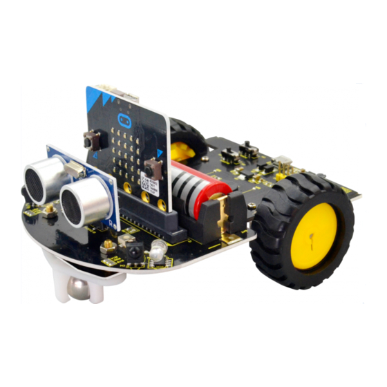
BBC. It is only half size of a credit card, onboard comes with Bluetooth, accelerometer, compass, three buttons, 5x5 LED matrix, mainly used for teens programming education. The Micro:bit Mini Smart Robot Car integrates ultrasonic and infrared obstacle avoidance as well as line following. Also comes with a passive buzzer for playing music. -
Page 5: Packing List
5) Dimensions: 120*90.7mm 6) Environmental attributes: ROHS 3. Packing List Item Quantity Image Micro:bit main board keyestudio Micro:bit smart robot shield (Black and Eco-friendly) Keyestudio line tracking sensor (Black and Eco-friendly) - Page 6 HC-SR04 ultrasonic sensor JST PH2.0MM-5PIN double-head cable length 55MM W420 steel universal wheel 18650 red battery 3500mah (self prepare) N20 motor wheel diameter:43mm ; width: 19mm ; hole diameter: 3mm type D ABS plastic + rubber yellow...
- Page 7 M3 Nickel plated nut Single pass M3*6mm+6mm hex copper pillar M3*6MM round-head screw yellow-black handle 3*40MM phillips screwdriver USB cable A/MICRO OD: 4.0 Black with magnetic spring L=1.2m Eco-friendly...
-
Page 8: Installation Method
4. Installation Method a. Firstly prepare all the assembly components. Place them together before install the micro:bit robot car. - Page 9 b. The first step should mount 2pcs hex copper pillar and 2pcs M3 Nickel plated nut on the front of car shield. Front view Back view c. Connect the JST PH2.0MM-5PIN double-head cable to line tracking sensor.
- Page 10 d. Then fix the line tracking sensor and W420 steel universal wheel onto the hex copper pillar on the car shield using 2pcs M3*6MM round-head screws.
- Page 13 e. After that, mount the 2pcs N20 motor wheels into the DC motor.
- Page 15 f. Now, we insert the ultrasonic sensor and micro:bit main board into the car shield.
- Page 17 g. Connect the JST PH2.0MM-5PIN cable connected to line tracking sensor to the car shield.
- Page 18 h. Finally, insert the 18650 battery into the car shield. Congrats! The mini micro:bit robot car is installed well. Pretty simple.
-
Page 19: Micro:bit Driver Installation
5. micro:bit Driver Installation Next, let’s install the driver for micro:bit main board. 1) First of all, connect the micro:bit to your computer using a USB cable. 2) Then, double click the driver software to install it. Here you can click the driver icon to download. - Page 21 3) After that, click Next to continue the installation.
- Page 22 4) Wait the driver installing finished.
- Page 23 5) Completing the driver installation.
- Page 24 6) Driver installation completed, then you can right click the “Computer” —> “Properties”—> “Device Manager”.
- Page 25 You can check the detailed Ports information shown as below.
-
Page 26: Micro:bit Example Use
6. micro:bit Example Use Step 1: Connect It Connect the micro:bit to your computer via a micro USB cable. Your micro:bit will show up on your computer as a drive called 'micro:bit'. -
Page 27: Step 2: Program It
Step 2: Program It Use micro:bit MakeCode Block editor https://makecode.micro:bit.org/ to write your first micro:bit code. You can drag and drop some example blocks and try your program on the Blocks Editor. Shown below. - Page 28 Click the JavaScript, you can see the corresponding program code. Shown as below figure.
-
Page 29: Step 3: Download It
Step 3: Download It Click the Download button in the editor. This will download a 'hex' file, which is a compact format of your program that your micro:bit can read. Here you can name the project as LED1, then click “Save”. Shown below. -
Page 30: Step 4: Play It
Once the hex file has downloaded, copy it to your micro:bit just like copying a file to a USB drive. On Windows you can right click the downloaded file and choose "Send To→micro:bit." Step 4: Play It The micro:bit will pause and the yellow 5*5 LED on the back of the micro:bit will display the images while your code is programmed. - Page 31 You can power it using USB cable or battery. The battery holder should connect two 1.5V AA batteries.
-
Page 32: Micro:bit Pins
7. micro:bit Pins Before getting started with the following projects, first need to figure out each pin of micro:bit main board. The BBC micro:bit has 25 external connections on the edge connector of the board, which we refer to as ‘pins’. - Page 33 www.keyestudio.com...
- Page 34 More reference you can click the link below: BBC micro bit Pins: http://micro:bit.org/guide/hardware/pins/ BBC micro:bit website: http://micro:bit.org/ Micro bit MakeCode Block Editor: https://makecode.micro:bit.org/ Meet micro:bit starter programming: http://micro:bit.org/guide/ BBC micro:bit Features Guide: http://micro:bit.org/guide/features/ BBC micro:bit Safety Warnings: http://micro:bit.org/guide/features/ BBC micro:bit Quick Start Guide:...
- Page 35 www.keyestudio.com...
- Page 36 www.keyestudio.com...
-
Page 37: Learning Projects
Different frequencies produce different sounds. You can use micro:bit to code the melody of a song, quite fun and simple. The keyestudio Micro:bit robot shield comes with a passive buzzer element. The signal terminal of buzzer is connected to the P9 interface of micro:bit main board. - Page 38 In the experiment, we make use of the software built-in library to drive the passive buzzer play a song of Happy Birthday.
- Page 39 2) Test Code...
- Page 40 3) Test Result Send well the test code to micro:bit main board, then insert the micro:bit main board into the micro:bit robot shield. Connect a 18650 battery to the shield, and turn the POWER and BUZZER switch ON. You should hear the micro:bit robot shield playing a song of《Happy Birthday》.
-
Page 41: Micro:bit Led Matrix Display
8.2 Micro:bit LED Matrix Display 1) Description LED stands for Light Emitting Diode. The micro:bit has 25 individually-programmable LEDs, allowing you to display text, numbers, and images. The micro:bit MakeCode Block editor has built-in library. So you can use it to control the 25 LED lights on and off, showing the different images. - Page 42 www.keyestudio.com...
- Page 43 3) Test Result Send well the test code to micro:bit main board, powered on, the micro:bit 25 LED lights show a big heart for one second, then show a small heart image for one second, repeatedly.
-
Page 44: Motor Driving
8.3 Motor Driving 1) Description The micro:bit robot shield has a built-in TB6612FNG chip. When using, you just need to insert the micro:bit main board into the shield, and send the test code to micro:bit main board. Insert well the 18650 battery into the shield to control the two motors rotate, thus control the micro:bit car run. - Page 45 Left motor control Right motor control Right Car state PWM(P0) Left motor PWM(P1) pin (P5) state pin(P16) state motor Forward Go forward Go forward Backward Go backward Go backward Stop Stop Stop Turn left Go backward Go forward Turn right...
- Page 46 2) Test Code...
- Page 47 3) Test Result Send well the test code to micro:bit main board, then insert the micro:bit main board into the car shield, and connect a 18650 battery into the car shield. Turn the POWER switch ON. The micro:bit car will go forward for 3 seconds, backward for 3 seconds, stop for 3...
-
Page 48: Line Tracking
During the process of detection, black is active at LOW level, but white is active at High level. The following picture is our keyestudio line tracking sensor designed for Micro:bit robot car. We have integrated 3 sets of TCRT5000 infrared tube on a single board, pretty convenient for wiring and controlling. - Page 49 www.keyestudio.com...
- Page 50 2) TECH SPECS Operating Voltage: 3.3-5V(DC) Interface: 5Pin connector Output Signal: digital signal 3) Test Code...
- Page 51 www.keyestudio.com...
- Page 52 4) Test Result Send the test code to micro:bit main board, then insert the micro:bit main board into the car shield and connect a 18650 battery, turn the POWER switch ON. At this moment, the micro:bit LED matric has no display.
- Page 53 www.keyestudio.com...
- Page 54 www.keyestudio.com...
- Page 55 www.keyestudio.com...
-
Page 56: Line Tracking Car
8.4.2 Line Tracking Car 1) Description In the previous section, we have introduced the principle and application of line tracking module and motor driving. After that, combine the tracking sensor and module to build a line following car. So at first what does line tracking mean? It refers to follow the line trajectory. You might often see some robots always follow or track a black line. - Page 57 2) Programming Thinking At first judge the middle tracking sensor. If it detects a black line, no matter detect a black line on either side, the micro:bit car always goes forward. If the middle tracking sensor does not detect a black line, then judge the sensor on both sides.
- Page 58 www.keyestudio.com...
- Page 59 4) Test Result Send the test code to micro:bit main board, then insert the micro:bit main board into the car shield and connect a 18650 battery, turn the POWER switch ON. At this moment, the micro:bit mini robot car will follow a black line.
- Page 60 www.keyestudio.com...
-
Page 61: Ultrasonic Avoiding Obstacles
8.5 Ultrasonic Avoiding Obstacles 8.5.1 Ultrasonic Ranging 1) Description There is an animal called bat in nature. The bats can fly at night, not depend on its eyes, but on its ears and vocal organs. When the bat flies, it will emit a scream, an ultrasonic signal that humans cannot hear because of its high audio frequency. - Page 62 Ultrasonic sensor has a wide range of sensitivity, no blind area, and no interference with obstacles. As the following picture shown, it is our keyestudio ultrasonic module. It has two somethings like eyes. One is transmitting end, the other is receiving end.
- Page 63 2) TECH SPECS: Operating Voltage: 5V(DC) Operating Current: 15mA Operating Frequency: 40khz Maximum Detection Distance: 3-5m Minimum Detection Distance: 3-4cm Sensing Angle: less than 15 degrees 3) Test Code...
- Page 64 www.keyestudio.com...
- Page 65 4) Test Result Send the test code to micro:bit main board, then insert the micro:bit main board into the car shield and connect a 18650 battery, turn the POWER switch ON. At this moment, when the micro:bit mini robot car detects an obstacle ahead, the measured result will be showed on the micro:bit LED matrix.
- Page 66 www.keyestudio.com...
- Page 67 www.keyestudio.com...
-
Page 68: Ultrasonic Obstacle Avoiding Car
8.5.2 Ultrasonic Obstacle Avoiding Car 1) Description In the previous project, we have combined a tracking sensor and micro:bit car shield to build a line tracking car. Here we combine a ultrasonic module and micro:bit car shield to build an ultrasonic obstacle avoiding car. - Page 69 2) Programming Thinking At first, use a ultrasonic module to measure the distance between the micro:bit car and an obstacle ahead. When the measured distance is less than 10cm, the micro:bit car stops for 0.2 second, then turns left for 0.5 second and then goes forward.
- Page 70 www.keyestudio.com...
- Page 71 4) Test Result Send the test code to micro:bit main board, then insert the micro:bit main board into the car shield and connect a 18650 battery, turn the POWER switch ON. At this moment, if the micro:bit robot car encounters an obstacle ahead, it will turn left to a certain angle, then...
- Page 72 www.keyestudio.com...
-
Page 73: Infrared Avoiding Obstacles
8.6 Infrared Avoiding Obstacles 8.6.1 Infrared Detection 1) Description The micro:bit robot car shield comes with two infrared obstacle detector sensors. It is actually designed for infrared obstacle avoidance robot. The infrared obstacle detector sensor has a pair of infrared transmitting and receiving tubes. - Page 74 10cm.
- Page 75 2) Test Code...
- Page 76 3) Test Result Send the test code to micro:bit main board, then insert the micro:bit main board into the car shield and connect a 18650 battery, turn the POWER switch ON. The two infrared obstacle detector sensors on the micro:bit mini robot car can used to detect an obstacle ahead.
- Page 77 www.keyestudio.com...
- Page 78 www.keyestudio.com...
- Page 79 www.keyestudio.com...
- Page 80 www.keyestudio.com...
-
Page 81: Infrared Obstacle Avoiding Car
8.6.2 Infrared Obstacle Avoiding Car 1) Description In the previous project, we have combined sensor and micro:bit car shield to build a specific function car. Now, we use an infrared obstacle detector module and motor driving circuit on the micro:bit car shield to build an infrared obstacle avoiding car. - Page 82 If detects an obstacle on the left side but not on the right side, the car will turn right for 0.05 second. If detects an obstacle on the right side but not on the left side, the car will turn left for 0.1 second.
- Page 83 www.keyestudio.com...
- Page 84 4) Test Result Send the test code to micro:bit main board, then insert the micro:bit main board into the car shield and connect a 18650 battery, turn the POWER switch ON. The left infrared sensor on the car shield detects an obstacle, the car will turn right at a certain angle and then go forward.
-
Page 85: Ultrasonic And Infrared Avoiding Obstacles
8.7 Ultrasonic and Infrared Avoiding Obstacles 1) Description In the previous sections, we have introduced ultrasonic obstacle avoiding car and infrared obstacle avoiding car. To be more accurate, this lesson we combine both ultrasonic module and infrared obstacle detector sensors to build an obstacle avoiding car. - Page 86 If detects an obstacle on the left side but not on the right side, the car will turn right. If detects an obstacle on the right side but not on the left side, the car will turn left.
- Page 87 www.keyestudio.com...
- Page 88 4) Test Result Send the test code to micro:bit main board, then insert the micro:bit main board into the car shield and connect a 18650 battery, turn the POWER switch ON. When the front obstacle distance measured by ultrasonic sensor is greater than 10cm.
- Page 89 forward.
-
Page 90: Bluetooth Controlled Car
8.8 Bluetooth Controlled Car 8.8.1 Bluetooth Test 1) Description The micro:bit robot car shield comes with a Bluetooth module. We can use the built-in Bluetooth module to communicate with your phone’s APP, thus control the external devices connected to micro:bit control board using APP. - Page 91 2) Library link settings The micro:bit robot car shield comes with a Bluetooth module. Before sending the test code, we should add the library to micro:bit on the browser. The method is as below. Connect the micro:bit main board to your computer using a USB cable.
- Page 92 www.keyestudio.com...
- Page 93 Then click the Bluetooth. TAP Remove extensions and add Bluetooth.
- Page 94 www.keyestudio.com...
- Page 95 Finally, you should see the Bluetooth is added well.
- Page 96 Then click the Extensions again, enter the library link below and search: https://github.com/LaboratoryForPlayfulComputation/pxt-BlockyTalkyBLE-UART...
- Page 97 Finally, you should see the library blocky Talky BLE is added successfully.
- Page 98 3) Test Code...
- Page 99 4) Bluetooth APP Use After add the library and send the test code to micro:bit main board, power on the micro:bit main board.
- Page 100 Click the link to download the Bluetooth APP: https://drive.google.com/open?id=17jJB--GKxPytDyPuqqhs6B2NUCCu7kST Installed the APP, click the APP icon to open it. When your phone detects the Bluetooth module on the micro:bit main board, the APP will prompt to open the Bluetooth. Choose to open the Bluetooth. Pop up the interface below.
- Page 101 Then click the Bluetooth icon , it will pop up the micro:bit information.
- Page 102 Then click to connect the micro:bit Bluetooth.
- Page 103 After that, click for connection, pop up the interface shown below.
- Page 104 Here the Bluetooth is connected successfully, you can use the APP to control your micro:bit car. The options are shown on the right side.
- Page 105 You can click the to disconnect the Bluetooth. Shown below.
- Page 106 5) Test Result Send well the test code to micro:bit main board, and power on the micro:bit main board. Follow the method mentioned above, connect the Bluetooth on the micro:bit main board using your phone’s APP. Connected, click the right icons on the APP, the LED matrix on the micro:bit main board should show different...
- Page 107 www.keyestudio.com...
-
Page 108: Bluetooth Controlled Car
8.8.2 Bluetooth Controlled Car 1) Description In the previous projects, we have combined the sensors and robot shield to make the specific function car. In this project, we use the shield’s motor driving circuit and Bluetooth module to build a Bluetooth controlling car. - Page 109 Bluetooth connected, click front, the APP will send the char “F”, controlling the car forward; if click back, it will send the char “B”, controlling the car backward; if click left, it will send the char “L”, controlling the car turn left;...
- Page 110 www.keyestudio.com...
- Page 111 4) Test Result Send the test code to micro:bit main board, then insert the micro:bit main board into the car shield and connect a 18650 battery, turn the POWER switch ON. When your phone’s APP is connected to Bluetooth module, the built-in LED matrix on the micro:bit main board should show the heart shape.
- Page 112 www.keyestudio.com...
-
Page 113: Wireless Gamepad Control
8.8.3 Wireless Gamepad Control Description Apart from the Andriod APP controlling Bluetooth mentioned above, you can also control the micro:bit through IOS Bluetooth wireless programming and control. Test Code... - Page 114 www.keyestudio.com...
- Page 115 Pay close attention to: When open the MakeCode Editor, click the icon , select the project settings, shown below.
- Page 116 www.keyestudio.com...
- Page 117 How to control the car through IOS Bluetooth programming? Step 1: Open the App store on your ipad/iPhone. Step 2: Search the micro:bit to download and install.
- Page 118 www.keyestudio.com...
- Page 119 Step 3: open the micro:bit interface, click Choose micro:bit.
- Page 120 Then click Pair a micro:bit, and click Next.
- Page 121 Step 4: power on the micro:bit main board, HOLD the A and B buttons, then press and release RESET button. The micro:bit main board will enter the Bluetooth pairing mode. You should see an image showing on the LED matrix.
- Page 122 Step 5: copy the pattern from your micro:bit device and tap Next.
- Page 123 Continue to tap Next to pair.
- Page 124 OK, pairing successful!
- Page 125 How to control your micro:bit car using the Bluetooth? Step 1: press down the RESET button on the micro:bit main board. Then TAP the Monitor and Control on the APP interface.
- Page 126 Step 2: Tap the Add and then select the Gamepad.
- Page 127 And you should see the control interface shown below. Click Start to connect.
- Page 128 Connection successful! Click Stop to disconnect.
- Page 129 Test Result When you press the key A, the micro:bit car goes front; press the key B, go back; press the key C, turn left; press the key D, turn right; press Stop, disconnect the Bluetooth, the car will stop.
- Page 130 www.keyestudio.com...
- Page 131 www.keyestudio.com...
-
Page 132: Related Resources Link
9. Related Resources Link You can download all the information needed from the link below: https://drive.google.com/open?id=1bIvuCCkZ8lT9uoF6YkpzBCCk0ptlvqGS Download the micro:bit driver: https://drive.google.com/open?id=1YbX1_Wjy3IpcEWjqrx0x1CTyJPjToP9d Download the Bluetooth APP: https://drive.google.com/open?id=17jJB--GKxPytDyPuqqhs6B2NUCCu7kST Download the User Guide: https://drive.google.com/open?id=1mqcH3-G_wu85ziQlWVoUKKYW71R45GXV Download all the test code: https://drive.google.com/open?id=18zSPeJhsjR4o7ZrDmZbj1Kohz-W5oMAQ...
Need help?
Do you have a question about the Micro:bit Mini Smart Robot Car and is the answer not in the manual?
Questions and answers