Table of Contents
Advertisement
Advertisement
Table of Contents

Related Manuals for Keyestudio 4DOF


Summary of Contents for Keyestudio 4DOF
- Page 1 4DOF Robot Mechanical Arm Kit for Arduino DIY...
-
Page 2: Table Of Contents
CONTENT GUIDE 1. Kit Overview................................................1 2. Kit Features................................................1 3. Part List..................................................3 4. Assembly Guide............................................... 11 Step1: Begin with the Baseplate Assembly.....................................11 Step2: Assemble Arm Middle Parts........................................28 Step3: Assemble the Claw Servo Plate......................................65 Step4: Final Assembly............................................79 Step5: Assemble the Joystick Control Plate....................................87 5. -
Page 3: Table Of Contents
Project 4: Bluetooth Controlled Robot Arm....................................199 1) Principle of Bluetooth Control......................................199 2) Bluetooth Control Key Test......................................... 201 3) Bluetooth Controlling Arm........................................206 Project 5: PS2 Controlled Robot Arm (Extension)..................................214 1) PS2 Joypad Key Test..........................................214 2) PS2 Joypad Control..........................................223 3) PS2 Controlling Posture Memory....................................... 235 4) PS2 Controlling Posture Memory And Loop.................................. -
Page 4: Kit Overview
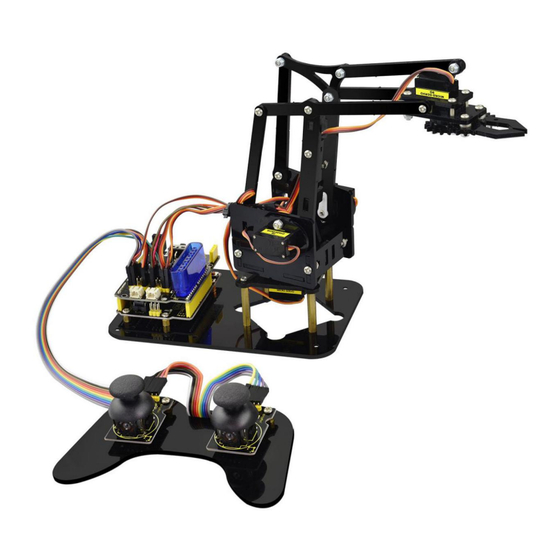
DIY your own controllable mechanical arm using ARDUINO microcontroller. It uses UNO R3 and 2 JoyStick modules to control the angle degree of 4 servos. When DIY this 4DOF robot arm kit, you could get everything needed for arm installation and debugging. There are 3 controlling methods are as follows: 1) Controlling through Wired JoyStick (included in the kit);... - Page 5 Detailed debugging methods, starting Arduino from entry. Three controlling methods: Wired JoyStick Control; Phone Bluetooth Control; Wireless PS2 JoyStick Control. The parameters of keyestudio TB6612FNG motor/servo drive expansion board are as follows: VIN voltage: VIN = DC 7-15V VIN current: 5A ...
-
Page 6: Part List
3. Part List You can see a pretty beautiful packaging box for the arm kit, and inside the packaging you will find all the parts and screws listed below. Picture Item Quantity Keyestudio UNO R3 Main Board keyestudio TB6612FNG motor/servo drive shield... - Page 7 MeArm T=3MM Black Acrylic panels MeArm T=3MM Black Acrylic handle MeArm Black ABS Cylindrical holder Diameter 42mm...
- Page 8 Black 180° Servo Keyestudio Bluetooth Module-(HC-06) Keyestudio Joystick Module 3D PS2 Joystick cap...
- Page 9 Yellow-black handle 3*40MM Phillips Screwdriver Galvanized M2+M3 2mm thin double-headed small wrench M3*6MM round-head cross screw M3*10MM round-head cross screw M3*16MM round-head screw...
- Page 10 M3*14MM flat-head screw M3*12MM round-head cross screw M3*24+6MM copper pillar M3*6mm+6mm copper pillar M3 Stainless steel Hex Nut...
- Page 11 M3 hexagon Lock Nut M1.2x5MM Phillips tapping screw M2x5MM Phillips tapping screw M3 304 Stainless steel flat washer 3*7*0.5MM...
- Page 12 M2x8MM Phillips tapping screw M3*16MM flat-head screw Male to female 10CM jumper wire female to female 50CM jumper wire...
- Page 13 Black 3*100MM cable ties 18650 dual-cell battery case with plug lead 15CM...
-
Page 14: Assembly Guide
4. Assembly Guide Follow the assembly steps below to build your own robot arm, believe you will be full of delight to experience the robot arm DIY. If still confused, you can refer to the assembly video. Step1: Begin with the Baseplate Assembly (1) Firstly, you should prepare the components as follows: ... - Page 15 Then, screw the copper pillars with M3 hex nuts on the black Acrylic baseplate. Rear Front...
- Page 16 (2) Then install the control board, and prepare the components as follows: M3*6MM round-head screw *3 Keyestudio UNO R3 board *1 keyestudio TB6612FNG motor shield *1...
- Page 17 Firstly, screw the UNO R3 board on the pillar using three M3*6MM round-head screws.
- Page 18 Then stack the motor drive shield onto the UNO R3 board.
- Page 19 (3) Completed the above assembly, let's mount the Pivot Servo Plate onto the base. M3*12MM round-head screw *2 M3 hex lock Nut *2 Black 180° servo *1 Acrylic plate * 4...
- Page 20 Note: before install the servo, should set the servo angle to 80 degrees. To set the servo angle, first connect the servo to A0 of motor shield, upload the code below to UNO R3 board, powered on, press the reset button, servo will rotate to 80°.
- Page 21 Code for 80° Servo: ************************************************* int servopin=A0;//Define digital interface A0 to connect servo steering gear signal line int myangle; //Define angle variables int pulsewidth; //Define pulse width variables void setup() pinMode(servopin,OUTPUT); //Set steering gear interface as Output void servopulse(int servopin,int myangle) //Define Function pulsewidth=(myangle*11)+500;...
- Page 22 //80 Degree Code: servopulse(servopin,80); //180 Degree Code: servopulse(servopin,180); ************************************************* Notice: Set well the servo angle and complete the below servo base plate assembly, power off the servo to avoid the angle error and make sure the servo can rotate freely. Don’t over-tighen the screws.
- Page 23 Adjusted well the servo motor, start to install the Servo Base Plate. Follow the marks.
- Page 24 Firstly mount the acrylic plate to the servo motor. ②...
- Page 25 Then mount the two acrylic plates to the servo using two M3*12MM round-head screws. ④...
- Page 26 After that, screw the acrylic plate to the servo using two M3 hex lock Nuts ⑤ ⑥...
- Page 27 You should get the detailed view shown below (pay close attention to red mark). Front Rear...
- Page 28 You should get the complete Servo Base Part.
- Page 29 (4) Now you should install the Servo Base part to the Base Plate: M3*6MM round-head hex screw *4...
- Page 30 Install the Servo plate to the Base Plate using four M3*6MM round-head hex screws.
-
Page 31: Step2: Assemble Arm Middle Parts
Step2: Assemble Arm Middle Parts (1) In the following section, assemble the Left Arm Servo Plate. Prepare: M3*12MM round-head screw *2 M3 hex lock nut *2 M2x5MM Phillips tapping screw *1 M2x8MM Phillips tapping screw *1 ... - Page 32 Note: before install the servo plate, should set the servo angle to 180 degrees. The method is the same as 80° servo settings mentioned above. You just need to change the servopulse(servopin,80) into servopulse(servopin,180) in the code.
- Page 33 Now assemble the Left Arm Servo Plate as below. (pay close attention to servo direction, rocker connected to servo and marked position)
- Page 34 Firstly mount the acrylic plate to the Left servo motor. ②...
- Page 35 Second, mount the two acrylic plates to the servo using two M3*12MM round-head screws . You ④ ③ can get the Left servo plate shown below.
- Page 36 Then screw the Left servo plate to acrylic plate using two M3 hex lock Nuts . Get the Left servo ⑤ ⑥ base plate shown below. Front Rear...
- Page 37 After that, screw the acrylic plate joint and white servo mount to the Left servo base plate using a ⑦ M2x8MM tapping screw and a M2x5MM tapping screw ⑧...
- Page 38 Finally you should get the complete Left Arm Servo Plate. Shown below.
- Page 39 (2) We will now attach a servo mount to the Arm Bottom Plate. M2x8MM Phillips tapping screw *2 White servo mount *1 Acrylic bottom plate *1 Black Cylindrical holder *1...
- Page 40 Fix the white servo mount and black Cylindrical holder on the acrylic plate using two M2x8MM Phillips tapping screws. Front Rear...
- Page 41 (3) Completed the above assembly, move on to the Right Arm Servo Plate. M3*12MM round-head screw *2 M3 hex lock nut *2 M2x5MM Phillips tapping screw *1 M2x8MM Phillips tapping screw *1 Black 180° servo *1 ...
- Page 42 Note: before install the servo, should set the servo angle to 0 degrees. The method is the same as 80° servo settings mentioned above. You just need to change the servopulse(servopin,80) into servopulse(servopin,0) in the code.
- Page 43 Now assemble the Right Arm Servo Plate as below. (pay close attention to servo direction, rocker connected to servo and marked position)
- Page 44 Firstly mount the acrylic plate to the Right servo motor. ②...
- Page 45 Second, mount the two acrylic plates to the servo using two M3*12MM round-head screws ④ ③...
- Page 46 Then screw the Right servo plate to acrylic plate using two M3 hex lock Nuts ⑤ ⑥ Rear Front...
- Page 47 After that, screw the short acrylic plate joint and white servo mount to the Right servo motor using a ⑦ M2x8MM tapping screw and a M2x5MM tapping screw ⑧...
- Page 49 Finally you should get the complete Left Servo Plate. Shown below.
- Page 50 (4) Next install the Servo Wrist Joint. M3*10MM round-head screw *1 M3 hex lock nut *1 Acrylic plate*2...
- Page 51 Fix the two Acrylic plates together using a M3*10MM screw and a M3 lock nut. You can get the Wrist Joint Plate shown below.
- Page 52 (5) The above parts are installed well. Mount the Wrist Joint and Left Arm Servo Plate together. M3*10MM round-head screw *2 M3 hex nut *2 Acrylic plate*1 Left Arm Servo Plate Wrist Joint Plate...
- Page 53 Install both Left Arm Servo Plate and Wrist Joint plate to a single acrylic plate using two M3 hex nuts and two M3*10MM round-head screws.
- Page 54 You should get the complete parts shown below.
- Page 55 (6) Complete the whole Arm Base Parts. M3*10MM round-head screw *4 M3 hex nut *4 Acrylic plate *2 Arm Bottom Plate ⑥ Left Arm Servo Plate ① Right Arm Servo Plate ⑦...
- Page 56 Mount the Acrylic plate to Left Arm Servo Plate using a M3*10MM round-head screw and a M3 hex ② ① ③...
- Page 57 Then screw another Acrylic plate ④ Left Arm Servo Plate using a ① M3*10MM round-head screw and a M3 hex nut.
- Page 58 After that, snap the Arm Bottom Plate between the both side plate of Arm BasePlate. ⑥...
- Page 59 At last, mount the Right Arm Servo Plate to the BasePlate using two M3*10MM round-head screws ⑦ and two M3 hex nuts.
- Page 60 With this step completed, the Arm Base Parts is really starting to take shape!
- Page 62 (7) Now we should install the Wrist Joint Connector between the Left and the Right Wrist Joint. M3*10MM round-head screw *7 M3*12MM round-head screw *1 M3 hex lock nut *8 Acrylic plate*6 Arm Base Parts ①...
- Page 63 Fix well the Acrylic plates ②③④.
- Page 64 Then screw them to Arm Base Parts with 7 M3*10MM screws, a M3*12MM screw and 8 M3 lock nuts. ① Don’t over-tighten the screws as they serve as pivot points to allow the robot arm to move.
- Page 65 (Note: only red circle there use the M3*12MM screw, other wrist joints all use M3*10MM screw.)
- Page 66 Installed well.
-
Page 68: Step3: Assemble The Claw Servo Plate
Step3: Assemble the Claw Servo Plate (1) We are now on the final stretch, it’s time to work on the claw. M3*16MM flat-head screw *2 M3*16MM round-head screw *2 M3 hex lock nut *4 Black 180° servo *1 ... - Page 69 Note: before install the claw servo motor, should set the servo angle to 0 degrees. The method is the same as 80° servo settings mentioned above. You just need to change the servopulse(servopin,80) into servopulse(servopin,0) in the code.
- Page 70 We will start by mounting the Claw Servo Motor Plate.
- Page 71 Fix well the Acrylic Plates , and insert the servo motor. Get the servo plate shown below. ②③④...
- Page 72 Then tighten a Acrylic Plate to the above servo plates using two M3*16MM flat-head screws and two ⑤ M3*16MM round-head screws and four M3 hex nuts.
- Page 73 (2) Next is to install the Gripper Plate. M1.2x5MM Phillips tapping screw *4 M2x5MM Phillips tapping screw *4 White servo mount *1 Gripper Acrylic plate *3...
- Page 74 Firstly fix the white servo mount onto acrylic plate using four M1.2x5MM tapping screws ② ① ③ Rear view Front view...
- Page 75 Then fix the acrylic plate onto another longer acrylic plate using four M2x5MM tapping screws. ④ ⑤...
- Page 76 (3) Mount the grippers onto the claw servo plate. M3*12MM round-head screw *2 M3 hex lock nut *2 M3 flat washer *7 Servo screw *1 ① Claw servo plate ② Gripper plate ③ Gripper plate ④...
- Page 77 Place the four flat washers onto a M3*12MM round-head screw connected to the Claw servo plate.
- Page 78 ③. N Then fix a M3 hex lock nut to the Gripper plate ext, place the Gripper plate onto Claw servo plate.
- Page 79 After that, place another Gripper plate onto Claw servo plate using 3 flat washers and a M3*12MM ⑤ round-head screw.
- Page 80 Finally, screw the Gripper plate onto the shaft of servo motor with a servo screw. ④...
- Page 81 Claw servo plate completed!
-
Page 82: Step4: Final Assembly
Step4: Final Assembly (1) Now we will assemble all the finished parts together M3*10MM round-head screw *3 M3 hex lock nut *1 M2x5MM tapping screw *1 Servo Base Plate ① Arm Middle Parts ② Claw Servo Plate ③... - Page 83 Mount the Claw Servo Plate to Arm Middle Parts using three M3*10MM round-head screws and a ③ ② M3 hex lock nut.
- Page 86 After that, screw them to Servo Base Plate using a M2x5MM tapping screw. ①...
- Page 88 The robot arm kit is nearly complete! It’s now time to connect the servo to drive shield. Hookup Guide:...
-
Page 90: Step5: Assemble The Joystick Control Plate
Step5: Assemble the Joystick Control Plate (1) The last step is to assemble the Joystick control plate M3*6MM round-head screw *4 M3*6+6mm single-pass copper pillar *6 M3 hex nut *6 Joystick module *2 Black Joystick plate *1... - Page 91 Mount 6 single-pass copper pillars onto Joystick plate with 6 M3 hex nuts. Rear view Front view...
- Page 92 Then screw the two Joystick modules onto the Acrylic plate using four M3*6MM round-head screws.
- Page 93 (2) Finally connect the Joystick module to drive shield using female-to-female jumper wires.
- Page 94 Hookup Guide:...
- Page 95 Congrats! Your robot arm kit is complete! Done wiring, power and program everything up to give your robot arm kit a try!
-
Page 96: Robot Arm Projects
Robot Arm Projects Project 1: Getting Started with ARDUINO 1) UNO Control Board When it comes to using the UNO R3 as core of our robot, the UNO is the best board to get started with electronics and coding. If this is your first experience tinkering with the platform, the UNO is the most robust board you can start playing with. - Page 98 USB Connection Arduino board can be powered via USB connector. Or you can program the board via the USB port. DC Power Jack Arduino board can be supplied with power from the DC power jack Voltage Regulator To control the voltage provided to the Arduino board, as well as to stabilize the DC voltage used by the processor and other components.
- Page 99 Arduino RESET You can reset your Arduino board, for example, start the program from the very beginning. Firstly, use the RESET button(17). Or you can connect an external reset button to Arduino pin 5 labeled RESET. Pin Header(3.3V,5V,GND,Vin) 3.3V - provides 3.3V output voltage 5V - provides 5V output voltage Using 3.3 volts and 5 volts, most components can normally operate with Arduino board together.
- Page 100 Microcontroller Each Arduino board has its own microcontroller. You can regard it as the brain of your board. The main IC (integrated circuit) on the Arduino is slightly different from the panel pair. Microcontrollers are usually from ATMEL. Before you load a new program from the Arduino IDE, you must know what IC is on your board.
- Page 101 TX and RX LED Onboard you can find two labels: RX(receive ) and TX (transmit) First appear on digital pin 0 and 1 for serial communication; Besides, the RX LED on the board will flash in different speed when serial data is being transmitted. The flash speed depends on the baud rate set by board.
- Page 102 Installing Arduino IDE When you get the control board, first you should install the Arduino software and driver. You can see all the Arduino software versions from the link below: https://www.arduino.cc/en/Main/OldSoftwareReleases#1.5.x Or you can browse the ARDUINO website at this link, https://www.arduino.cc, pop up the following interface.
- Page 103 Then click the SOFTWARE on the browse bar, you will have two options ONLINE TOOLS and DOWNLOADS. Click DOWNLOADS, it will appear the latest software version of ARDUINO 1.8.5 shown as below.
- Page 104 In this software page, on the right side you can see the version of development software for different operating systems. So ARDUINO has a rather powerful compatibility. You should download the software that is compatible with the operating system of your computer.
- Page 105 In our project, we will take WINDOWS system as an example here. There are also two options under Windows system, one is installed version, the other is non-installed version. For simple installed version, first click Windows Installer, you will get the following page.
- Page 106 This way you just need to click JUST DOWNLOAD, then click the downloaded file to install it.
- Page 107 For non-installed version, first click Windows ZIP file, you will also get the pop-up interface as the above figure. Click JUST DOWNLOAD, and when the ZIP file is downloaded well to your computer, you can directly unzip the file and then click the icon of ARDUINO program to start it. Installing Arduino (Windows) Install Arduino with the exe.
- Page 108 Click “I Agree” to see the following interface. Click “Next” . Pop up the interface below.
- Page 109 You can press Browse… to choose an installation path or directly type in the directory you want. Then click “Install” to initiate installation.
- Page 110 Wait for the installing process, if appear the interface of Window Security, just continue to click Install to finish the installation.
- Page 111 All right, up to now, you have completed the Arduino setup! The following icon will appear on your PC desktop.
- Page 112 Double-click the icon of Arduino to enter the desired development environment shown as below.
- Page 113 Installing Driver Next, we will introduce the board driver installation. The driver installation may have slight difference in different computer systems. So in the following let’s move on to the driver installation in the WIN 7 system. The Arduino folder contains both the Arduino program itself and the drivers that allow the Arduino to be connected to your computer by a USB cable.
- Page 114 Then right-click on the device and select the top menu option (Update Driver Software...) shown as the figure below.
- Page 115 It will then be prompted to either “Search Automatically for updated driver software” or “Browse my computer for...
- Page 116 driver software”. Shown as below. In this page, select “Browse my computer for driver software”.
- Page 117 After that, select the option to browse and navigate to the “drivers” folder of Arduino installation.
- Page 118 Click “Next” and you may get a security warning, if so, allow the software to be installed. Shown as below. Once the software has been installed, you will get a confirmation message. Installation completed, click “Close”.
- Page 119 Up to now, the driver is installed well. Then you can right click “Computer” —>“Properties”—>“Device manager” , you should see the device as the figure shown below.
-
Page 121: Example Use Of Arduino Ide
2) Example Use of ARDUINO IDE STEP 1: Open Arduino IDE In the previous, we have introduced the Arduino installation. So this time let’s first have basic understanding of the ARDUINO development environment. After that, you will learn how to upload the program to Arduino board. First of all, open the unzipped folder of ARDUINO development software and click icon of ARDUINO to open the software, as the figure shown below. - Page 123 STEP 2: Build Projects When open the Arduino software, you will have two options as below: Build a new project Open an exiting project example If you want to build a new project, please select “File”→then click “New”, you will see the software interface as follows.
- Page 125 If you want to open an example project, please select File→Example→Basics→Blink . Shown below.
- Page 126 STEP 3: Select Arduino Board On the Arduino software, you should click Tools→Board , select the correct board. Here in our tutorial we should select Arduino Uno. Shown as below.
- Page 127 STEP 4: Select Serial Port If you are not sure which port is correct, at first directly open the Control Panel of your computer, then click to open Device Manager , you can check the COM port here. Shown as below.
- Page 128 Then you should click Tools→Serial Port. It may be COM3 or higher.
- Page 129 STEP 5: Upload the Code to Your Board Before showing you how to upload the code to your board, you can check the function of each icon on the Tool bar of Arduino IDE listed below: Check the code for errors Verify/Compile Upload the current Sketch to the Arduino...
- Page 130 Show a list of Sketches Open Save the current Sketch Save Display the serial data being sent from the Arduino Serial Monitor...
-
Page 131: Project 2: Joint Rotation And Pin Control
Project 2: Joint Rotation and Pin Control 1) Joint Rotation and Servo Angle Settings Name 0° 180° Servo 1(baseplate) Rotate toward the rightmost Rotate toward the leftmost Servo 2(right side) Rocker arm connected to Servo 2 draws back stretch out Servo 3(left side)... -
Page 132: Pin Control
2) Pin Control Name IO Pin Servo 1 (baseplate) Servo 2 (right side) Servo 3 (left side) Servo 4 (clamp claw) Right Joystick X Right Joystick Y Right Joystick Z (key) Left Joystick X Left Joystick Y Left Joystick Z... - Page 133 D1/DAT of PS2 D0/CMD of PS2 CE/SEL of PS2 CLK of PS2...
-
Page 134: Project 3: Joystick Controlled Robot Arm
Project 3: JoyStick Controlled Robot Arm 1) Servo Control How to adjust the Servo Angel Hookup Guide:... - Page 135 Code to Note: In the previous assembly, we have set the square wave and servo angle. So we should use the servo libraries to control the angle of each servo. The test result is the same. Before using, place the Servo folder inside the libraries folder of Arduino IDE directory, then open the Arduino IDE, and the libraries are able to use.
- Page 136 Automatic Turning Description: In the previous section, you have learned to set the Servo angle. In fact, we just need to continually change the angle of 4 Servo motors, thus make the 4DOF robot arm operate different motions. Hookup Guide:...
- Page 138 Test Code 2: ******************************************************************************************************************************* #include <Servo.h> Servo myservo1; // create servo object to control a servo Servo myservo2; Servo myservo3; Servo myservo4; int pos1=80, pos2=60, pos3=130, pos4=0; void setup() myservo1.attach(A1); // attaches the servo on pin 9 to the servo object myservo2.attach(A0);...
- Page 139 void loop() // turn right for(pos1;pos1>0;pos1--) myservo1.write(pos1); delay(5); // delay 5ms(used to adjust the servo speed) delay(1000); // open the claw for(pos4;pos4<100;pos4++) myservo4.write(pos4); delay(1000); // right servo rotates to 100 degrees for(pos2;pos2>50;pos2--) myservo2.write(pos2); delay(5); // left servo rotates to 5 degrees for(pos3;pos3>50;pos3--)
- Page 140 myservo3.write(pos3); delay(5); delay(1500); // close the claw for(pos4;pos4>0;pos4--) myservo4.write(pos4); delay(1000); // left servo rotates to100 degrees, rocker arm lifts. for(pos3;pos3<120;pos3++) myservo3.write(pos3); delay(5); delay(1000); // turn to left for(pos1;pos1<180;pos1++) myservo1.write(pos1); delay(5);...
- Page 141 delay(1000); // Lower the arm for(pos3;pos3>50;pos3--) myservo3.write(pos3); delay(5); delay(1000); // open the claw for(pos4;pos4<100;pos4++) myservo4.write(pos4); delay(1000); // lift up the arm for(pos3;pos3<120;pos3++) myservo3.write(pos3); delay(5); delay(1000);...
- Page 142 // close the claw for(pos4;pos4>0;pos4--) myservo4.write(pos4); delay(1000); ************************************************************************************************************************************ Test Result: Stack the drive shield onto UNO R3 board and connect the servo motor, upload well the code. Powered on, press the reset button, the robot arm will realize a cyclic motion. Turn to the right, stretch out the arm, lower, the claw is clamped;...
-
Page 143: Read The Joystick Value
2) Read the JoyStick Value Description: The sensor’s pin X, Y are for analog sensor, so directly read the measured analog value. Pin Z is a digital button, first should set the pin to Input status and then read the measured value 1 (pressed down) or 0 (not press). Check out the value printed on the serial monitor. - Page 144 Test Code 3: ******************************************************************************************************************************* const int right_X = A2; // define the right X pin to A2 const int right_Y = A5; // define the right Y pin to A5 const int right_key = 7; //define the right key pin to 7(that is the value Z) const int left_X = A3;...
- Page 145 y1 = analogRead(right_Y); // read the value of right Y z1 = digitalRead(right_key); //// read the value of right Z x2 = analogRead(left_X); // read the value of left X y2 = analogRead(left_Y); // read the value of left Y z2 = digitalRead(left_key);...
- Page 146 Test Result: Hook it up and upload well the code. Connect the UNO R3 to computer using a USB cable, then open the serial monitor and set the baud rate to 9600, you should see the analog value of the right Joystick pin X,Y.
-
Page 147: Dual-Joystick Controlling
In the previous section, we have introduced how to use 4 Servo to control the robot arm. Next, combine those two experiments. Use two Joystick modules to control 4DOF robot arm realize different motions. At first, set the boot posture. The Joystick control is shown as below table. - Page 148 Servo 3 gradually reduces to Servo 2 gradually reduces to 0° ( that is, lift up Y1>1000 Y2>1000 35° ( that is, stretch out the the robot upper arm) robot lower arm) Servo 2 gradually reduces to 180° ( that is, lower Servo 3 gradually increases to Y1<50 Y2<50...
- Page 150 Test Code 4: ************************************************************************************************************************ #include <Servo.h> // add the servo libraries Servo myservo1; // create servo object to control a servo Servo myservo2; Servo myservo3; Servo myservo4; int pos1=80, pos2=60, pos3=130, pos4=0; // define the variable of 4 servo angle,and assign the initial value (that is the boot posture angle value) const int right_X = A2;...
- Page 151 void setup() // boot posture myservo1.write(pos1); delay(1000); myservo2.write(pos2); myservo3.write(pos3); myservo4.write(pos4); delay(1500); pinMode(right_key, INPUT); // set the right/left key to INPUT pinMode(left_key, INPUT); Serial.begin(9600); // set the baud rate to 9600 void loop() myservo1.attach(A1); // set the control pin of servo 1 to A1 myservo2.attach(A0);...
- Page 152 x2 = analogRead(left_X); //read the left X value y2 = analogRead(left_Y); //read the left Y value z2 = digitalRead(left_key); // read the left Z value //delay(5); // lower the speed overall // claw zhuazi(); // rotate zhuandong(); // upper arm xiaobi();...
- Page 153 if(pos4<2) // if pos4 value subtracts to 2, the claw in 37 degrees we have tested is closed. //(should change the value based on the fact) pos4=2; // stop subtraction when reduce to 2 if(x2>1000) //// if push the left joystick to the left pos4=pos4+8;...
- Page 154 if(pos1<1) // limit the angle when turn right pos1=1; if(x1>1000) // if push the right joystick to the let pos1=pos1+1; //pos1 plus 1 myservo1.write(pos1); // arm turns left delay(5); if(pos1>180) // limit the angle when turn left pos1=180; //**********************************************************/ //upper arm void xiaobi() if(y1>1000) // if push the right joystick upward pos2=pos2-1;...
- Page 155 if(pos2<0) // limit the lifting angle pos2=0; if(y1<50) // if push the right joystick downward pos2=pos2+1; myservo2.write(pos2); // upper arm will go down delay(5); if(pos2>180) // limit the angle when go down pos2=180; //*************************************************************/ // lower arm void dabi() if(y2<50) // if push the left joystick upward pos3=pos3+1;...
- Page 156 // limit the retracted angle pos3=35; *************************************************************************************************************************** Test Result: Upload the code to main board and stack the shield onto it. Wire it up, 4DOF robot arm will keep the initial position, push the two Joysticks to operate the robot arm.
-
Page 157: Add Memory Function
4) Add Memory Function Memorize One Posture Description: In the previous section, use the analog value of pin X,Y of 2 Joystick modules to control the robot arm. In the following experiment, we add a memory function for the robot arm, making it remember a posture then operate. - Page 158 Test Code 5:...
- Page 159 ******************************************************************************************************************************* #include <Servo.h> // add servo libraries Servo myservo1; // create servo object to control a servo Servo myservo2; Servo myservo3; Servo myservo4; int pos1=80, pos2=60, pos3=130, pos4=0; // define the variable of 4 servo angle and assign the initial value( that is the boot posture angle value) const int right_X = A2;...
- Page 160 myservo2.write(pos2); myservo3.write(pos3); myservo4.write(pos4); delay(1500); pinMode(right_key, INPUT); // set the right/left key to INPUT pinMode(left_key, INPUT); Serial.begin(9600); // set the baud rate to 9600 void loop() myservo1.attach(A1); // set the control pin of servo 1 to A1 myservo2.attach(A0); // set the control pin of servo 2 to A0 myservo3.attach(6);...
- Page 161 if(z1==1) // if the right joystick key is pressed delay(10); // delay for eliminating shake if(z1==1) // judge again if the right key is pressed s1=myservo1.read(); // read the angle value of each servo s2=myservo2.read(); s3=myservo3.read(); s4=myservo4.read(); if(z2==1) // if the left key is pressed delay(10);...
- Page 162 pos1++; //pos1 plus 1 delay(5); // delay for 5ms,controlling the rotation speed of servo. else // if angle of servo 1 is greater than the value stored in array 1. while(pos1>s1) //while loop,rotate the servo to the position of the value stored in the array. myservo1.write(pos1);...
- Page 163 while(pos2>s2) myservo2.write(pos2); pos2--; delay(5); //************************************************* // the explanation is the same as servo 1 if(pos3<s3) while(pos3<s3) myservo3.write(pos3); pos3++; delay(5); else while(pos3>s3) myservo3.write(pos3); pos3--; delay(5);...
- Page 164 //************************************************* // the explanation is the same as servo 1 if(pos4<s4) while(pos4<s4) myservo4.write(pos4); pos4++; delay(5); else while(pos4>s4) myservo4.write(pos4); pos4--; delay(5);...
- Page 165 //claw zhuazi(); //turn zhuandong(); // upper arm xiaobi(); // lower arm dabi(); //claw void zhuazi() //claw if(x2<50) // if push the left joystick to the right pos4=pos4-2; // current angle of servo 4 subtracts 2(change the value you subtract, thus change the closed speed of claw) //Serial.println(pos4);...
- Page 166 if(x2>1000) //// if push the left joystick to the left pos4=pos4+8; // current angle of servo 4 plus 8(change the value you plus, thus change the open speed of claw) //Serial.println(pos4); myservo4.write(pos4); // servo 4 operates the motion, the claw gradually opens. delay(5);...
- Page 167 if(x1>1000) // if push the right joystick to the left pos1=pos1+1; //pos1 plus 1 myservo1.write(pos1); // robot arm turns left delay(5); if(pos1>180) // limit the angle when turn left pos1=180; //**********************************************************/ // upper arm void xiaobi() if(y1>1000) // if push the right joystick upward pos2=pos2-1;...
- Page 168 if(y1<50) // if push the right joystick downward pos2=pos2+1; myservo2.write(pos2); // the upper arm will go down delay(5); if(pos2>180) // limit the angle when go down pos2=180; //*************************************************************/ // lower arm void dabi() if(y2>1000) // if push the left joystick upward pos3=pos3-1;...
- Page 169 if(y2<50) // if push the left joystick downward pos3=pos3+1; myservo3.write(pos3); // the lower arm will draw back delay(5); if(pos3>180) // limit the retracted angle pos3=180; ********************************************************************************************************************************** Test Result: Wire it up, stack the shield onto UNO R3, upload the code. Powered on, press the key Z1 of right Joystick to save the angle value of 4 servos control.
- Page 170 To extend the experiment, next make it remember several postures, at most 10 (you can set it in the code), then make 4DOF robot arm continually operate the posture in memory. That is, make robot arm memorize a group of actions, and you can set the memorizing speed in the code.
- Page 172 Test Code 6: ******************************************************************************************************************************* #include <Servo.h> // add the servo libraries Servo myservo1; // create servo object to control a servo Servo myservo2; Servo myservo3; Servo myservo4; int pos1=80, pos2=60, pos3=130, pos4=0; // define the variable of 4 servo angle and assign the initial value( that is the boot posture angle value) const int right_X = A2;...
- Page 173 int jiyi3[10]; // if need to save more data, just change the number 10 to be more larger number. int jiyi4[10]; int i=0; // for loop int j=0; // save the last value of i void setup() // boot posture myservo1.write(pos1);...
- Page 174 myservo4.attach(9); // set the control pin of servo 4 to D9 x1 = analogRead(right_X); // read the right X value y1 = analogRead(right_Y); // read the right Y value z1 = digitalRead(right_key); // read the right Z value x2 = analogRead(left_X); // read the left X value y2 = analogRead(left_Y);...
- Page 175 Serial.println(s4); jiyi1[i]=s1; // Save the read servo value to the array sequentially jiyi2[i]=s2; jiyi3[i]=s3; jiyi4[i]=s4; i++; //i value plus 1 j=i; // assign the last value of i to j delay(100); Serial.println(i); // on the serial monitor, print out the value i if(z2==1) // if the left joystick key is pressed delay(10);...
- Page 176 if(pos1<jiyi1[k]) // if the current servo 1 angle is less than the value stored in array 1. while(pos1<jiyi1[k]) //while loop, make servo turn to the position of value stored in the array. myservo1.write(pos1); // servo 1 performs the action delay(5); // delay 5ms,controlling the servo rotating speed pos1++;...
- Page 177 myservo2.write(pos2); delay(5); pos2++; //Serial.println(pos1); else while(pos2>jiyi2[k]) myservo2.write(pos2); delay(5); pos2--; //Serial.println(pos1); //*************************************************************** // the explanation is the same as the previous servo if(pos3<jiyi3[k]) while(pos3<jiyi3[k]) myservo3.write(pos3); delay(5); pos3++;...
- Page 178 //Serial.println(pos1); else while(pos3>jiyi3[k]) myservo3.write(pos3); delay(5); pos3--; //Serial.println(pos1); //*************************************************************** //the explanation is the same as the previous servo if(pos4<jiyi4[k]) while(pos4<jiyi4[k]) myservo4.write(pos4); delay(5); pos4++; //Serial.println(pos1);...
- Page 179 else while(pos4>jiyi4[k]) myservo4.write(pos4); delay(5); pos4--; //Serial.println(pos1); //claw zhuazi(); //turn zhuandong(); //upper arm xiaobi(); // lower arm dabi(); //claw...
- Page 180 void zhuazi() //claw if(x2<50) // if push the left joystick to the right pos4=pos4-2; // angle of servo 4, subtract 2 (change the value you subtract, thus change the closed speed of claw) //Serial.println(pos4); myservo4.write(pos4); // servo 4 operates the motion and claw is gradually closed. delay(5);...
- Page 181 //****************************************************** // turn void zhuandong() if(x1<50) // if push the right joystick to the right pos1=pos1-1; //pos1 subtracts 1 myservo1.write(pos1); // servo 1 operates the motion and robot arm turns right delay(5); if(pos1<1) // limit the angle when turn right pos1=1;...
- Page 182 //**********************************************************/ // upper arm void xiaobi() if(y1>1000) // if push the right joystick upward pos2=pos2-1; myservo2.write(pos2); // the upper arm will lift delay(5); if(pos2<0) // limit the lifting angle pos2=0; if(y1<50) // if push the right joystick downward pos2=pos2+1; myservo2.write(pos2); // the upper arm will go down delay(5);...
- Page 183 //*************************************************************/ // lower arm void dabi() if(y2>1000) // if push the left joystick upward pos3=pos3-1; myservo3.write(pos3); // the lower arm will stretch out delay(5); if(pos3<35) // limit the stretched angle pos3=35; if(y2<50) // if push the left joystick downward pos3=pos3+1; myservo3.write(pos3);...
- Page 184 ************************************************************************************************************************************ Test Result: Wire it up, stack the shield onto UNO R3, upload the code. Powered on, press the key Z1 of right Joystick to save the angle value of 4 servos. Press down the key Z1 to memorize different postures, at most 10 postures in the code. If need to memorize more postures, you can set it in the code.
- Page 185 That is, when robot arm performs all the memorized actions, it will not stop, and continue to repeat those actions. In the following experiment, press the key Z1, 4DOF robot arm will exit the looping action. Press the key Z1 again, start to memorize the posture, after that, press the key Z2 to loop the memorized actions.
- Page 188 Test Code 7: ******************************************************************************************************************************* #include <Servo.h> // add the servo libraries Servo myservo1; // create servo object to control a servo Servo myservo2; Servo myservo3; Servo myservo4; int pos1=80, pos2=60, pos3=130, pos4=0; // define the variable of 4 servo angle and assign the initial value( that is the boot posture angle value) const int right_X = A2;...
- Page 189 int jiyi4[20]; int i=0; // for loop int j=0; // save the last value of i void setup() // boot posture myservo1.write(pos1); //turn servo 1 to 90 degrees delay(1000); myservo2.write(pos2); // turn servo 2 to 90 degrees myservo3.write(pos3); // turn servo 3 to 120 degrees myservo4.write(pos4);...
- Page 190 x1 = analogRead(right_X); // read the right X value y1 = analogRead(right_Y); //read the right Y value z1 = digitalRead(right_key); //read the right Z value x2 = analogRead(left_X); // read the left X value y2 = analogRead(left_Y); // read the left Y value z2 = digitalRead(left_key);...
- Page 191 jiyi1[i]=s1; // Save the read servo value to the array sequentially jiyi2[i]=s2; jiyi3[i]=s3; jiyi4[i]=s4; i++; //i plus 1 j=i; // assign the last value of i to j delay(100); // delay 100ms Serial.println(i); // print out the value i if(z2==1) // if the left joystick key is pressed delay(10);...
- Page 192 while(pos1<jiyi1[k]) //while loop, make servo turn to the position of value stored in the array. myservo1.write(pos1); //servo 1 performs the action delay(5); //delay 5ms,controlling the servo rotating speed. pos1++; //pos1 plus 1 //Serial.println(pos1); else //if the current servo 1 angle is greater than the value stored in array 1. while(pos1>jiyi1[k]) //while loop, make servo turn to the position of value stored in the array.
- Page 193 delay(5); pos2++; //Serial.println(pos1); else while(pos2>jiyi2[k]) myservo2.write(pos2); delay(5); pos2--; //Serial.println(pos1); //********************************************* //the explanation is the same as the previous servo. if(pos3<jiyi3[k]) while(pos3<jiyi3[k]) myservo3.write(pos3); delay(5); pos3++; //Serial.println(pos1);...
- Page 194 else while(pos3>jiyi3[k]) myservo3.write(pos3); delay(5); pos3--; //Serial.println(pos1); //********************************************* //the explanation is the same as the previous servo. if(pos4<jiyi4[k]) while(pos4<jiyi4[k]) myservo4.write(pos4); delay(5); pos4++; //Serial.println(pos1); else while(pos4>jiyi4[k])
- Page 195 myservo4.write(pos4); delay(5); pos4--; //Serial.println(pos1); //************************************************************ // for exiting the loop z1 = digitalRead(right_key); // read the right Z value if(z1==1) // if the right key is pressed delay(10); //eliminate the shake if(z1==1) // if the key z1 is pressed pos1=jiyi1[(j-1)]; // assign the last angle value saved in array to pos pos2=jiyi2[(j-1)];...
- Page 196 //claw zhuazi(); //turn zhuandong(); //upper arm xiaobi(); //lower arm dabi(); //claw void zhuazi() //claw if(x2<50) // if push the left joystick to the right pos4=pos4-2; // angle of servo 4, subtract 2 (change the value you subtract, thus change the closed speed of claw) //Serial.println(pos4);...
- Page 197 //(should change the value based on the fact) pos4=2; //stop subtraction when reduce to 2 if(x2>1000) ////if push the left joystick to the left pos4=pos4+8; //current angle of servo 4 plus 8(change the value you plus, thus change the open speed of claw) //Serial.println(pos4);...
- Page 198 pos1=1; if(x1>1000) // if push the right joystick to the left pos1=pos1+1; //pos1 plus 1 myservo1.write(pos1); //the robot arm turns left. delay(5); if(pos1>180) //limit the left turning angle pos1=180; //**********************************************************/ // upper arm void xiaobi() if(y1>1000) // if push the right joystick upward pos2=pos2-1;...
- Page 199 pos2=0; if(y1<50) // if push the right joystick downward pos2=pos2+1; myservo2.write(pos2); // the robot arm will go down delay(5); if(pos2>180) // limit the declining angle pos2=180; //*************************************************************/ // lower arm void dabi() if(y2>1000) // if push the left joystick upward pos3=pos3-1;...
- Page 200 pos3=35; if(y2<50) // if push the right joystick downward pos3=pos3+1; myservo3.write(pos3); // the lower arm will draw back delay(5); if(pos3>180) // limit the retraction angle pos3=180; ************************************************************************************************************************************ Test Result: Wire it up, stack the shield onto UNO R3, upload the code. Powered on, press the key Z1 of right Joystick to save the angle value of 4 servos.
- Page 201 When memorizing successfully, press down the key Z2 of left Joystick to make the robot arm carry out several postures stored successively, looping. Long press the key Z1, 4DOF robot arm will exit the looping action. Press the key Z1 again, start to memorize the posture, after that, press the key Z2 to loop the memorized actions.
-
Page 202: Project 4: Bluetooth Controlled Robot Arm
Project 4: Bluetooth Controlled Robot Arm 1) Principle of Bluetooth Control Description: Bluetooth, as the name implies, blue teeth, and he is not used to bite people, but a wireless data transmission method. Bluetooth technology is a wireless standard technology that enables short-range data exchange among fixed devices, mobile devices, and personal area networks of buildings (UHF radio waves in the ISM band of 2.4 to 2.485 GHz). - Page 203 the HC-06 module. Note: HC-06 Bluetooth module is only compatible with Android system, not support Mac. Specification Parameters: Bluetooth Protocol: Bluetooth 2.1+ EDR Standard USB Protocol: USB v1.1/2.0 Operating Frequency: 2.4GHz ISM Frequency Band Modulation Mode: Gauss Frequency Shift Keying ...
-
Page 204: Bluetooth Control Key Test
2) Bluetooth Control Key Test Description: Next, we are going to introduce the use method for HC-06 Bluetooth module. To easily use the HC-06 Bluetooth module to control the robot arm, we particularly design the APP control. Shown below. - Page 205 You can download the APP from the link: https://drive.google.com/open?id=10U7EWyCyb5bGUxWm3DXRXGKEm1UQGU4Q There are 10 control keys on the App. When connect well the HC-06 Bluetooth module to Android phone using our APP, press the control key, Android phone will receive a corresponding value. When programming, you can set the function for the corresponding value.
- Page 206 Hookup Guide:...
- Page 207 Test Code 8: ******************************************************************************************************************** void setup() Serial.begin(9600); // set the serial baud rate to 9600 void loop() char val; // define a variable, used to receive the value read from Bluetooth. if(Serial.available()) // if receive the value val = Serial.read(); // assign the value read to val Serial.println(val);...
- Page 208 below. value three four five...
-
Page 209: Bluetooth Controlling Arm
3) Bluetooth Controlling Arm Description: In this experiment, we combine a Android APP and HC-06 Bluetooth module to control the robot arm. The controlling method are shown below. Corresponding arm action The lower arm stretches out The clamp claw opens three The clamp claw is closed four... - Page 210 The upper arm goes down Hookup Guide:...
- Page 211 Test Code 9: ****************************************************************************************************************************** #include <Servo.h> // add the servo libraries Servo myservo1; // create servo object to control a servo Servo myservo2; Servo myservo3; Servo myservo4; int pos1=80, pos2=60, pos3=130, pos4=0; // define the variable of 4 servo angle and assign the initial value( that is the boot posture angle value) char val;...
- Page 212 myservo1.attach(A1); // set the control pin of servo 1 to A1 myservo2.attach(A0); // set the control pin of servo 2 to A0 myservo3.attach(6); // set the control pin of servo 3 to D6 myservo4.attach(9); // set the control pin of servo 4 to D9 if(Serial.available()) // if receive the data val=Serial.read();...
- Page 213 pos1=pos1+1; myservo1.write(pos1); delay(5); if(pos1>180) pos1=180; //turn right void T_right() pos1=pos1-1; myservo1.write(pos1); delay(5); if(pos1<1) pos1=1; //******************************************** //open the claw void ZK() pos4=pos4-2; Serial.println(pos4);...
- Page 214 myservo4.write(pos4); delay(5); if(pos4<2) pos4=0; // close the claw void ZB() pos4=pos4+8; Serial.println(pos4); myservo4.write(pos4); delay(5); if(pos4>108) pos4=108; //****************************************** // the upper arm will lift up void RF() pos2=pos2-1; myservo2.write(pos2);...
- Page 215 delay(5); if(pos2<0) pos2=0; // the upper arm will go down void RB() pos2=pos2+1; myservo2.write(pos2); delay(5); if(pos2>180) pos2=180; //*************************************** // the lower arm will stretch out void LB() pos3=pos3+1; myservo3.write(pos3); delay(5); if(pos3>180)
- Page 216 pos3=180; // the lower arm will draw back void LF() pos3=pos3-1; myservo3.write(pos3); delay(5); if(pos3<35) pos3=35; ******************************************************************************************************************** Test Result: Upload the code, connect it up and power on, after connecting the Bluetooth APP, press the key to control the robot arm do commanded motions.
-
Page 217: Project 5: Ps2 Controlled Robot Arm (Extension)
Description: On the drive shield there is a PS2 Joystick connector, which is easy for you to control the 4DOF robot arm using the PS2 Joypad. But you need to purchase it by yourself because the PS2 Joypad is not included in the kit. - Page 218 Test Code 10: ************************************************************************************************************************* #include <PS2X_lib.h> //for v1.6 /****************************************************************** * set pins connected to PS2 controller: - 1e column: original - 2e colmun: Stef? * replace pin numbers by the ones you use ******************************************************************/ #define PS2_DAT 13 //14 #define PS2_CMD 11 //15 #define PS2_SEL 10 //16...
- Page 219 //#define rumble true #define rumble false PS2X ps2x; // create PS2 Controller Class //right now, the library does NOT support hot pluggable controllers, meaning //you must always either restart your Arduino after you connect the controller, //or call config_gamepad(pins) again after connecting the controller. int error = 0;...
- Page 220 Serial.print("pressures = "); if (pressures) Serial.println("true "); else Serial.println("false"); Serial.print("rumble = "); if (rumble) Serial.println("true)"); else Serial.println("false"); Serial.println("Try out all the buttons, X will vibrate the controller, faster as you press harder;"); Serial.println("holding L1 or R1 will print out the analog stick values."); Serial.println("Note: Go to www.billporter.info for updates and to report bugs.");...
- Page 221 type = ps2x.readType(); switch(type) { case 0: Serial.print("Unknown Controller type found "); break; case 1: Serial.print("DualShock Controller found "); break; case 2: Serial.print("GuitarHero Controller found "); break; case 3: Serial.print("Wireless Sony DualShock Controller found "); break; void loop() { /* You must Read Gamepad to get new values and set vibration values ps2x.read_gamepad(small motor on/off, larger motor strenght from 0-255) if you don't enable the rumble, use ps2x.read_gamepad();...
- Page 222 if(type == 2){ //Guitar Hero Controller ps2x.read_gamepad(); //read controller if(ps2x.ButtonPressed(GREEN_FRET)) Serial.println("Green Fret Pressed"); if(ps2x.ButtonPressed(RED_FRET)) Serial.println("Red Fret Pressed"); if(ps2x.ButtonPressed(YELLOW_FRET)) Serial.println("Yellow Fret Pressed"); if(ps2x.ButtonPressed(BLUE_FRET)) Serial.println("Blue Fret Pressed"); if(ps2x.ButtonPressed(ORANGE_FRET)) Serial.println("Orange Fret Pressed"); if(ps2x.ButtonPressed(STAR_POWER)) Serial.println("Star Power Command"); if(ps2x.Button(UP_STRUM)) //will be TRUE as long as button is pressed Serial.println("Up Strum");...
- Page 223 Serial.println("Select is being held"); if(ps2x.Button(ORANGE_FRET)) { // print stick value IF TRUE Serial.print("Wammy Bar Position:"); Serial.println(ps2x.Analog(WHAMMY_BAR), DEC); else { //DualShock Controller ps2x.read_gamepad(false, vibrate); //read controller and set large motor to spin at 'vibrate' speed if(ps2x.Button(PSB_START)) //will be TRUE as long as button is pressed Serial.println("Start is being held");...
- Page 224 if(ps2x.Button(PSB_PAD_DOWN)){ Serial.print("DOWN held this hard: "); Serial.println(ps2x.Analog(PSAB_PAD_DOWN), DEC); vibrate = ps2x.Analog(PSAB_CROSS); //this will set the large motor vibrate speed based on how hard you press the blue (X) button if (ps2x.NewButtonState()) { //will be TRUE if any button changes state (on to off, or off to on) if(ps2x.Button(PSB_L3)) Serial.println("L3 pressed");...
- Page 225 if(ps2x.Button(PSB_L1) || ps2x.Button(PSB_R1)) { //print stick values if either is TRUE Serial.print("Stick Values:"); Serial.print(ps2x.Analog(PSS_LY), DEC); //Left stick, Y axis. Other options: LX, RY, RX Serial.print(","); Serial.print(ps2x.Analog(PSS_LX), DEC); Serial.print(","); Serial.print(ps2x.Analog(PSS_RY), DEC); Serial.print(","); Serial.println(ps2x.Analog(PSS_RX), DEC); delay(50); ****************************************************************************************************************************** Test Result: Stack the drive shield onto UNO R3 and upload the code. Connecting the PS2 Joypad, open the serial monitor and set the baud rate to 57600.
-
Page 226: Ps2 Joypad Control
2) PS2 Joypad Control Description: In the previous section, we have showed how to use Joystick module to control the robot arm. It is almost the same for you to control the 4DOF robot arm using the PS2 Joypad. Hookup Guide:... - Page 227 Test Code 11: ************************************************************************************************************************* #include <PS2X_lib.h> PS2X ps2x; // create PS2 Controller Class //right now, the library does NOT support hot pluggable controllers, meaning //you must always either restart your Arduino after you connect the controller, //or call config_gamepad(pins) again after connecting the controller. int error = 0;...
- Page 228 // boot posture myservo1.write(pos1); delay(1000); myservo2.write(pos2); myservo3.write(pos3); myservo4.write(pos4); delay(1500); error = ps2x.config_gamepad(13,11,10,12); //setup GamePad(clock, command, attention, data) pins, check for error if(error == 0){ Serial.println("Found Controller, configured successful"); Serial.println("Try out all the buttons, X will vibrate the controller, faster as you press harder;"); Serial.println("holding L1 or R1 will print out the analog stick values.");...
- Page 229 //Serial.print(ps2x.Analog(1), HEX); ps2x.enableRumble(); //enable rumble vibration motors ps2x.enablePressures(); //enable reading the pressure values from the buttons. void loop(){ /* You must Read Gamepad to get new values Read GamePad and set vibration values ps2x.read_gamepad(small motor on/off, larger motor strenght from 0-255) if you don't enable the rumble, use ps2x.read_gamepad();...
- Page 230 ps2x.read_gamepad(false, vibrate); //read controller and set large motor to spin at 'vibrate' speed if(ps2x.Button(PSB_START)) //will be TRUE as long as button is pressed Serial.println("Start is being held"); if(ps2x.Button(PSB_SELECT)) Serial.println("Select is being held"); if(ps2x.Button(PSB_PAD_UP)) { //will be TRUE as long as button is pressed Serial.print("Up held this hard: ");...
- Page 231 vibrate = ps2x.Analog(PSAB_BLUE); //this will set the large motor vibrate speed based on //how hard you press the blue (X) button if (ps2x.NewButtonState()) //will be TRUE if any button changes state (on to off, or off to on) if(ps2x.Button(PSB_R3)) Serial.println("R3 pressed"); if(ps2x.Button(PSB_L3)) Serial.println("L3 pressed");...
- Page 232 if(ps2x.ButtonReleased(PSB_PINK)) //will be TRUE if button was JUST released Serial.println("Square just released"); if(ps2x.NewButtonState(PSB_BLUE)) //will be TRUE if button was JUST pressed OR released Serial.println("X just changed"); //转动 zhuandong(); //爪子 zhuazi(); //大臂 dabi(); //小臂 xiaobi(); if(ps2x.Button(PSB_L1) || ps2x.Button(PSB_R1)) // print stick values if either is TRUE Serial.print("Stick Values:");...
- Page 233 delay(5); //******************************************************************** // turn void zhuandong() //turn right if(ps2x.Analog (PSS_RX) > 200) // if push the right joystick to the right //Serial.println(ps2x.Analog(PSS_RX), DEC); pos1=pos1-1; //pos1 subtracts 1 myservo1.write(pos1); // servo 1 executes the action, the arm will turn right. // delay(5); if(pos1<1) // limit the right turning angle pos1=1;...
- Page 234 if(pos1>180) // limit the left turning angle pos1=180; //********************************************************************** // upper arm void xiaobi() //upper arm front if(ps2x.Analog(PSS_RY)<50) // if push the right joystick upward pos2=pos2-1; myservo2.write(pos2); // the upper arm will lift delay(5); if(pos2<0) // limit the lifting angle pos2=0;...
- Page 235 delay(5); if(pos2>180) // limit the declining angle pos2=180; //*************************************************************** void zhuazi() // close the claw if(ps2x.Analog(PSS_LX)>220) // if push the left joystick to the right pos4=pos4-1; Serial.println(pos4); myservo4.write(pos4); // servo 4 carries out the action and the claw is gradually closed. delay(5);...
- Page 236 Serial.println(pos4); myservo4.write(pos4); // servo 4 carries out the action and the claw is gradually opened delay(5); if(pos4>108) // limit the maximum opening angle pos4=108; //********************************************************* void dabi() // lower arm front if(ps2x.Analog(PSS_LY)>200) // if push the left joystick upward pos3=pos3+1; myservo3.write(pos3);...
- Page 237 myservo3.write(pos3); // the lower arm will draw back delay(5); if(pos3<35) // limit the retracted angle pos3=35; ****************************************************************************************************************************** Test Result: Stack the shield onto UNO R3 and upload the code. Powered on and connected the PS2 Joypad, you can use the PS2 Joypad to control the robot arm actions.
-
Page 238: Ps2 Controlling Posture Memory
3) PS2 Controlling Posture Memory Description: In the previous experiment, we have showed how to use Joystick module to control the robot arm memorize several postures. Now we replace the joystick module with PS2 Joypad. The program thought is almost the same. Hookup Guide:... - Page 239 Test Code 12: ************************************************************************************************************************* #include <PS2X_lib.h> #include <Servo.h> // add the servo libraries Servo myservo1; // create servo object to control a servo Servo myservo2; Servo myservo3; Servo myservo4; int pos1=80, pos2=60, pos3=130, pos4=0; // define the variable of 4 servo angle and assign the initial value( that is the boot posture angle value) PS2X ps2x;...
- Page 240 int jiyi4[20]; int i=0; int j=0; void setup() Serial.begin(57600); // boot posture myservo1.write(pos1); delay(1000); myservo2.write(pos2); myservo3.write(pos3); myservo4.write(pos4); delay(1500); error = ps2x.config_gamepad(13,11,10,12); //setup GamePad(clock, command, attention, data) pins, check for error if(error == 0){ Serial.println("Found Controller, configured successful"); Serial.println("Try out all the buttons, X will vibrate the controller, faster as you press harder;"); Serial.println("holding L1 or R1 will print out the analog stick values.");...
- Page 241 else if(error == 1) Serial.println("No controller found, check wiring, see readme.txt to enable debug. visit www.billporter.info for troubleshooting tips"); else if(error == 2) Serial.println("Controller found but not accepting commands. see readme.txt to enable debug. Visit www.billporter.info for troubleshooting tips"); //Serial.print(ps2x.Analog(1), HEX); ps2x.enableRumble();...
- Page 242 return; ps2x.read_gamepad(false, vibrate); //read controller and set large motor to spin at 'vibrate' speed if(ps2x.Button(PSB_START)) //will be TRUE as long as button is pressed Serial.println("Start is being held"); if(ps2x.Button(PSB_SELECT)) Serial.println("Select is being held"); if(ps2x.Button(PSB_PAD_UP)) { //will be TRUE as long as button is pressed Serial.print("Up held this hard: ");...
- Page 243 vibrate = ps2x.Analog(PSAB_BLUE); //this will set the large motor vibrate speed based on //how hard you press the blue (X) button if (ps2x.NewButtonState()) //will be TRUE if any button changes state (on to off, or off to on) if(ps2x.Button(PSB_R3)) //Serial.println("R3 pressed"); // record s1=myservo1.read();...
- Page 244 jiyi3[i]=s3; jiyi4[i]=s4; i++; j=i; // delay(100); Serial.println(i); if(ps2x.Button(PSB_L3)) //Serial.println("L3 pressed"); i=0; //执行 pos1 = myservo1.read(); pos2 = myservo2.read(); pos3 = myservo3.read(); pos4 = myservo4.read(); for(int k=0;k<j;k++) //for loop, to execute all the stored actions if(pos1<jiyi1[k]) //if the current servo 1 angle is less than the value stored in array 1. while(pos1<jiyi1[k]) //while loop, make servo turn to the position of value stored in the array.
- Page 245 pos1++; //Serial.println(pos1); else //if the current servo 1 angle is greater than the value stored in array 1. while(pos1>jiyi1[k]) //while loop, make servo turn to the position of value stored in the array. myservo1.write(pos1); // servo 1 executes the action delay(5);...
- Page 246 else while(pos2>jiyi2[k]) myservo2.write(pos2); delay(5); pos2--; //Serial.println(pos1); //***************************************************** //the same analysis if(pos3<jiyi3[k]) while(pos3<jiyi3[k]) myservo3.write(pos3); delay(5); pos3++; //Serial.println(pos1); else while(pos3>jiyi3[k])
- Page 247 myservo3.write(pos3); delay(5); pos3--; //Serial.println(pos1); //***************************************************** //the same analysis if(pos4<jiyi4[k]) while(pos4<jiyi4[k]) myservo4.write(pos4); delay(5); pos4++; //Serial.println(pos1); else while(pos4>jiyi4[k]) myservo4.write(pos4); delay(5); pos4--; //Serial.println(pos1);...
- Page 248 if(ps2x.Button(PSB_L2)) Serial.println("L2 pressed"); if(ps2x.Button(PSB_R2)) Serial.println("R2 pressed"); if(ps2x.Button(PSB_GREEN)) Serial.println("Triangle pressed"); if(ps2x.ButtonPressed(PSB_RED)) //will be TRUE if button was JUST pressed Serial.println("Circle just pressed"); if(ps2x.ButtonReleased(PSB_PINK)) //will be TRUE if button was JUST released Serial.println("Square just released"); if(ps2x.NewButtonState(PSB_BLUE)) //will be TRUE if button was JUST pressed OR released Serial.println("X just changed");...
- Page 249 // turn zhuandong(); // claw zhuazi(); // lower arm dabi(); // upper arm xiaobi(); if(ps2x.Button(PSB_L1) || ps2x.Button(PSB_R1)) // print stick values if either is TRUE Serial.print("Stick Values:"); Serial.print(ps2x.Analog(PSS_LY), DEC); //Left stick, Y axis. Other options: LX, RY, RX Serial.print(","); Serial.print(ps2x.Analog(PSS_LX), DEC); Serial.print(",");...
- Page 250 void zhuandong() //turn right if(ps2x.Analog (PSS_RX) > 200) // if push the right joystick to the right //Serial.println(ps2x.Analog(PSS_RX), DEC); pos1=pos1-1; //pos1 subtracts 1 myservo1.write(pos1); // servo 1 carries out the action and the arm will turn right // delay(5); if(pos1<1) // limit the right turning angle pos1=1;...
- Page 251 //********************************************************************** // upper arm void xiaobi() //upper arm front if(ps2x.Analog(PSS_RY)<50) // if push the right joystick upward pos2=pos2-1; myservo2.write(pos2); // the upper arm will lift up delay(5); if(pos2<0) // limit the lifting angle pos2=0; // upper arm back if(ps2x.Analog(PSS_RY)>200) //if push the right joystick downward pos2=pos2+1;...
- Page 252 //*************************************************************** void zhuazi() // close the claw if(ps2x.Analog(PSS_LX)>220) // if push the left joystick to the right pos4=pos4-1; Serial.println(pos4); myservo4.write(pos4); // servo 4 carries out the action and the claw is gradually closed. delay(5); if(pos4<0) // if pos4 value reduces to 37(the claw we test in 37degrees is closed) pos4=0;...
- Page 253 pos4=108; //********************************************************* void dabi() // lower arm front if(ps2x.Analog(PSS_LY)>200) // if push the left joystick upward pos3=pos3+1; myservo3.write(pos3); // the lower arm will stretch out delay(5); if(pos3>180) // limit the stretched angle pos3=180; if(ps2x.Analog(PSS_LY)<10) // if push the left joystick downward pos3=pos3-1;...
- Page 254 ****************************************************************************************************************************** Test Result: Stack the shield onto UNO R3 and upload the code. Powered on and connected the PS2 Joypad, you can use the PS2 Joypad to control the robot arm memorize several postures.
-
Page 255: Ps2 Controlling Posture Memory And Loop
4) PS2 Controlling Posture Memory And Loop Description: In the previous experiment, we have showed how to use Joystick module to control the robot arm memorize several postures and loop. Now we replace the Joystick module with the PS2 Joypad. The program is almost the same. - Page 256 Test Code 13: ************************************************************************************************************************* #include <PS2X_lib.h> #include <Servo.h> // add the servo libraries Servo myservo1; // create servo object to control a servo Servo myservo2; Servo myservo3; Servo myservo4; int pos1=80, pos2=60, pos3=130, pos4=0; // define the variable of 4 servo angle and assign the initial value( that is the boot posture angle value) PS2X ps2x;...
- Page 257 int jiyi2[30]; int jiyi3[30]; int jiyi4[30]; int i=0; int j=0,tt=0; void setup() Serial.begin(57600); // boot posture myservo1.write(pos1); delay(1000); myservo2.write(pos2); myservo3.write(pos3); myservo4.write(pos4); delay(1500); error = ps2x.config_gamepad(13,11,10,12); //setup GamePad(clock, command, attention, data) pins, check for error if(error == 0){ Serial.println("Found Controller, configured successful"); Serial.println("Try out all the buttons, X will vibrate the controller, faster as you press harder;");...
- Page 258 else if(error == 1) Serial.println("No controller found, check wiring, see readme.txt to enable debug. visit www.billporter.info for troubleshooting tips"); else if(error == 2) Serial.println("Controller found but not accepting commands. see readme.txt to enable debug. Visit www.billporter.info for troubleshooting tips"); //Serial.print(ps2x.Analog(1), HEX); ps2x.enableRumble();...
- Page 259 ps2x.read_gamepad(false, vibrate); //read controller and set large motor to spin at 'vibrate' speed if(ps2x.Button(PSB_START)) //will be TRUE as long as button is pressed Serial.println("Start is being held"); if(ps2x.Button(PSB_SELECT)) Serial.println("Select is being held"); if(ps2x.Button(PSB_PAD_UP)) { //will be TRUE as long as button is pressed Serial.print("Up held this hard: ");...
- Page 260 vibrate = ps2x.Analog(PSAB_BLUE); //this will set the large motor vibrate speed based on //how hard you press the blue (X) button if (ps2x.NewButtonState()) //will be TRUE if any button changes state (on to off, or off to on) if(ps2x.Button(PSB_R3)) //Serial.println("R3 pressed"); //record s1=myservo1.read();...
- Page 261 i++; j=i; // delay(100); Serial.println(i); // carry out if(ps2x.Button(PSB_L3)) //Serial.println("L3 pressed"); i=0; tt=1; pos1 = myservo1.read(); // record the angle value of 4 servo posture pos2 = myservo2.read(); pos3 = myservo3.read(); pos4 = myservo4.read(); while(tt==1) // repeat the actions for(int k=0;k<j;k++) //for loop, to execute all the stored actions.
- Page 262 myservo1.write(pos1); //servo 1 executes the action delay(5); //delay 5ms,controlling the rotating speed of servo. pos1++; //Serial.println(pos1); else //if the current servo 1 angle is greater than the value stored in array 1. while(pos1>jiyi1[k]) //while loop, make servo turn to the position of value stored in the array. myservo1.write(pos1);...
- Page 263 else while(pos2>jiyi2[k]) myservo2.write(pos2); delay(5); pos2--; //Serial.println(pos1); //***************************************************** // the same analysis as the previous servo if(pos3<jiyi3[k]) while(pos3<jiyi3[k]) myservo3.write(pos3); delay(5); pos3++; //Serial.println(pos1); else...
- Page 264 while(pos3>jiyi3[k]) myservo3.write(pos3); delay(5); pos3--; //Serial.println(pos1); //***************************************************** // the same analysis as the previous servo if(pos4<jiyi4[k]) while(pos4<jiyi4[k]) myservo4.write(pos4); delay(5); pos4++; //Serial.println(pos1); else while(pos4>jiyi4[k]) myservo4.write(pos4); delay(5);...
- Page 265 pos4--; //Serial.println(pos1); //******************************************************* // exit the looping ps2x.enableRumble(); //enable rumble vibration motors ps2x.enablePressures(); ps2x.read_gamepad(false, vibrate); vibrate = ps2x.Analog(PSAB_BLUE); if (ps2x.NewButtonState()) //will be TRUE if any button changes state (on to off, or off to on) if(ps2x.Button(PSB_R3)) tt=0; i=0; break; //********************************************************* if(ps2x.Button(PSB_L2))
- Page 266 Serial.println("L2 pressed"); if(ps2x.Button(PSB_R2)) Serial.println("R2 pressed"); if(ps2x.Button(PSB_GREEN)) Serial.println("Triangle pressed"); if(ps2x.ButtonPressed(PSB_RED)) //will be TRUE if button was JUST pressed Serial.println("Circle just pressed"); if(ps2x.ButtonReleased(PSB_PINK)) //will be TRUE if button was JUST released Serial.println("Square just released"); if(ps2x.NewButtonState(PSB_BLUE)) //will be TRUE if button was JUST pressed OR released Serial.println("X just changed");...
- Page 267 if(ps2x.Button(PSB_L1) || ps2x.Button(PSB_R1)) // print stick values if either is TRUE Serial.print("Stick Values:"); Serial.print(ps2x.Analog(PSS_LY), DEC); //Left stick, Y axis. Other options: LX, RY, RX Serial.print(","); Serial.print(ps2x.Analog(PSS_LX), DEC); Serial.print(","); Serial.print(ps2x.Analog(PSS_RY), DEC); Serial.print(","); Serial.println(ps2x.Analog(PSS_RX), DEC); delay(5); //******************************************************************** // turn void zhuandong() // turn right if(ps2x.Analog (PSS_RX) >...
- Page 268 // delay(5); if(pos1<1) // limit the right turning angle pos1=1; // turn left if(ps2x.Analog (PSS_RX) < 50) // if push the right joystick to the left //Serial.println(ps2x.Analog(PSS_RX), DEC); pos1=pos1+1; //pos1 plus 1 myservo1.write(pos1); // the robot arm turns left // delay(5); if(pos1>180) // limit the left turning angle pos1=180;...
- Page 269 pos2=pos2-1; myservo2.write(pos2); // the upper arm will lift up delay(5); if(pos2<0) // limit the lifting angle pos2=0; // upper arm back if(ps2x.Analog(PSS_RY)>200) //if push the right joystick to downward pos2=pos2+1; myservo2.write(pos2); // the robot arm will go down delay(5); if(pos2>180) // limit the declining angle pos2=180;...
- Page 270 pos4=pos4-1; Serial.println(pos4); myservo4.write(pos4); // servo 4 carries out the action and claw is gradually closed delay(5); if(pos4<0) // if pos4 value subtracts to 37, the claw in 37 degrees we have tested is closed.) pos4=0; // open the claw if(ps2x.Analog(PSS_LX)<10) // if push the left joystick to the left pos4=pos4+8;...
- Page 271 if(ps2x.Analog(PSS_LY)>200) // if push the left joystick upward pos3=pos3+1; myservo3.write(pos3); // the lower arm will stretch out delay(5); if(pos3>180) // limit the stretched angle pos3=180; if(ps2x.Analog(PSS_LY)<10) // if push the left joystick downward pos3=pos3-1; myservo3.write(pos3); // the lower arm will draw back delay(5);...
- Page 272 Test Result: Stack the shield onto UNO R3 and upload the code. Powered on and connected the PS2 Joypad, you can use the PS2 Joypad to control the robot arm memorize several postures, looping.
-
Page 273: More Resources
6. More Resources: You can get more reference from the links below: KEYESTUDIO WIKI: http://wiki.keyestudio.com/ ARDUINO Software: https://www.arduino.cc/en/Main/OldSoftwareReleases#1.5.x Detailed User Guide: https://drive.google.com/open?id=1R2ZPdKgTu1U1Xq4ZJEyIQewvL4wWueWJ Bluetooth APP Download: https://drive.google.com/open?id=1Ogl37dZywPXqLlN86H3D60R7omOLMky1 Libraries Download: https://drive.google.com/open?id=1mkCRozLVgOBwiv85KXTu61Df2Jn7rmM4 Arduino Project Code: https://drive.google.com/open?id=1iHGFJnnBRoq9ODAcodIXZxtUzLQM_ous Servo Test Code: https://drive.google.com/open?id=1qmQ8FsJNvxwqYV4vVaIYT5ytA1TU37Ga Assembly Video Link:... - Page 274 Great! It's just the beginning of ARDUINO programming journey. There are more and more awesome projects for you to explore. Furthermore, our KEYESTUDIO research and development team will continue to explore on this path, walking you through the basics up to complex projects. Hope that you can enjoy our works! About keyestudio Located in Shenzhen, the Silicon Valley of China, KEYES DIY ROBOT CO.,LTD is a thriving technology company...
-
Page 275: Customer Service
US Amazon storefront: http://www.amazon.com/shops/A26TCVWBQE4D9T CA Amazon storefront: http://www.amazon.ca/shops/A26TCVWBQE4D9T UK Amazon storefront: http://www.amazon.co.uk/shops/A39F7KX4U3W9JH DE Amazon storefront: http://www.amazon.de/shops/A39F7KX4U3W9JH FR Amazon storefront: http://www.amazon.de/shops/A39F7KX4U3W9JH ES Amazon storefront: http://www.amazon.de/shops/A39F7KX4U3W9JH IT Amazon storefront: http://www.amazon.de/shops/A39F7KX4U3W9JH US Amazon storefront: http://www.amazon.com/shops/APU90DTITU5DG CA Amazon storefront: http://www.amazon.ca/shops/APU90DTITU5DG JP Amazon storefront: http://www.amazon.jp/shops/AE9VWCCXQIC6J Customer Service As a continuous and fast growing technology company, we keep striving our best to offer you excellent products and quality service as to meet your expectation. - Page 276 You can reach out to us by simply drop a line at keyestudio@126.com Thank you in advance.
Need help?
Do you have a question about the 4DOF and is the answer not in the manual?
Questions and answers