Table of Contents
Advertisement
www.keyestudio.com
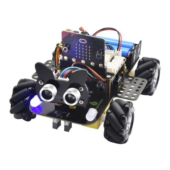
Keyestudio 4WD Mecanum Robot Car
(Makecode)
Contents
1. Introduction ................................................................................................................. 4
2. Description ................................................................................................................... 6
3.Parameters .................................................................................................................... 6
4.Kit List ............................................................................................................................. 7
5.Preparations: .............................................................................................................. 12
1
Advertisement
Table of Contents

Subscribe to Our Youtube Channel
Related Manuals for Keyestudio 4WD


Summary of Contents for Keyestudio 4WD
-
Page 1: Table Of Contents
Keyestudio 4WD Mecanum Robot Car (Makecode) Contents 1. Introduction ......................... 4 2. Description ........................6 3.Parameters ........................6 4.Kit List ..........................7 5.Preparations: ......................12... - Page 2 6.Keyestudio 4WD Mecanum Robot Car .............. 18 6.1.Basic Information about Keyestudio 4WD Mecanum Robot Car ... 18 6.2. the Installation of keyestudio 4WD Mecanum Robot Car ....20 7.Get Started with Micro:bit ..................42 7.1 Write code and program: ................ 42 7.2.Makecode:...
- Page 3 Project 5: Temperature Measurement ............113 Project 6: Geomagnetic Sensor ..............127 Project 7: Accelerometer ................. 142 Project 8: Light Detection ................157 Project 9: Speaker ....................163 Project 10: Touch-sensitive Logo ..............169 Project 11: Microphone ................... 175 Project 12: Bluetooth Wireless Communication ........
-
Page 4: Introduction
Project 20: Bluetooth Multi-purpose Smart Car ........348 20.1: Read Bluetooth Data ..............348 20.2: Multi-purpose Smart Car .............. 363 9. Resources: ........................ 369 1. Introduction Have you wondered to learn programming or have your own programming robot? Nowadays, programming has developed to a lower... - Page 5 This Keyestudio 4WD Mecanum Robot Car is a smart DIY car specially designed for micro:bit. The smart car kit consists of a car body with extended functions, a PCB base plate with integrated motor drive sensors, 4 decelerating DC motors, Mecanum wheels, various modules and sensors and acrylic boards.
-
Page 6: Description
2. Description This product is a smart car based on Micro:bit. It boasts multiply functions including ultrasonic sound following, line tracking, infrared control and Bluetooth control. It comes with a passive buzzer which is able to play music, 4 WS2812RGB LEDs to display different colors, 2 colorful lights to make direction lights for the car. -
Page 7: Kit List
Note: working voltage of micro:bit is 3.3V, driver shield integrates 3.3V/5V communication conversion circuit. 4.Kit List Quanti Picture Components KS0511 Acrylic Board T=3mm Acrylic Board with Lego Holes T=3mm 4.5V Motor 23*15*5MM Fixing Board... - Page 8 Servo Mecanum Wheels Keyestudio Micro:bit IO Port Expansion Sensor Shield With Level Conversion Micro:bit Main Board V2.0 with Package for KS4031 Micro:bit Main Board V2.0 for KS4032...
- Page 9 Keyestudio Driver Board M3*20MM Dual-pass Copper Pillar 4265c Lego Part 43093 Lego Part Acrylic Gasket Six in One Pack...
- Page 10 M3*6MM Round Head Screw Keyestudio Ultrasonic Module M3 Nickle-plated Nut M3*30MM Round Head Screw M2 Nickle-plated Nut M2*8MM Round Head Screw...
- Page 11 M3*8MM Round Head Screw Remote Control (without batteries) Plastic String 3*100mm USB Cable HX-2.54 2P DuPont Wire 100mm HX-2.54 4P DuPont Wire 50mm XH2.54 DuPont Wire 160mm XH2.54 3P DuPont Wire 50mm...
-
Page 12: Preparations
3*40mm Screwdriver M1.2*5mm Round Head Self-tapping Screw 5.Preparations: 5.1Background Information about Micro:bit ( 1 )What is Micro:bit? Micro:bit is an open source hardware platform based on the ARM architecture launched by British Broadcasting Corporation (BBC) together with ARM, Barclays, element14, Microsoft and other institutions. The core device is a 32-bit Arm Cortex-M4 with FPU micro-processing. -
Page 13: 2 )Layout
Moreover, this board has a sleeping mode to lower power consumption of batteries and it can be entered if users long press the Reset & Power button on the back of it. It is capable of reading the data of sensors, controlling servos and RGB lights and attaching with a shield so as to connect with various sensors. -
Page 14: 3 ) Pinout
: https://tech.microbit.org/hardware/ https://microbit.org/new-microbit/ https://www.microbit.org/get-started/user-guide/overview/ https://microbit.org/get-started/user-guide/features-in-depth/ ( 3 ) Pinout... - Page 15 The functions of pins: P0,P1,P2,P3,P4,P5,P6,P7,P8,P9,P10,P11,P12, GPIO P13,P14,P15,P16,P19,P20 ADC/DAC P0,P1,P2,P3,P4,P10 P19(SCL),P20(SDA) P13(SCK),P14(MISO),P15(MOSI) PWM(used P0,P1,P2,P3,P4,P10 frequently) PWM(not P5、P6、P7、P8、P9、P11、P12、P13、P14、P15、P16、P19、 frequently used)...
-
Page 16: 4 )Notes For The Application Of Micro:bit Main Board
P3(LED Col3),P4(LED Col1),P5(Button A),P6(LED Col4), Occupied P7(LED Col2),P10(LED Col5),P11(Button B) Browse the official website for more details: https://tech.microbit.org/hardware/edgeconnector/ https://microbit.org/guide/hardware/pins/ ( 4 )Notes for the application of Micro:bit main board a. It is recommended to cover it with a silicone protector to prevent short circuit for it has a lot of sophisticated electronic components. -
Page 17: Install Micro:bit Driver
When using pins(P3, P4, P6, P7 and P10)shared with the LED dot matrix, blocking them from the matrix or the LEDs may display randomly and the data about sensors connected maybe wrong. e. Pin 19 and 20 can not be used as IO ports though the Makecode shows they can. -
Page 18: Keyestudio 4Wd Mecanum Robot Car
6.Keyestudio 4WD Mecanum Robot Car This chapter will introduce the function and structure of keyestudio 4WD Mecanum Robot Car. It is a programmable car based on BBC micro:bit. Driven by motors, it boasts a line tracking sensor and an infrared receiver integrated into the bottom plate, an ultrasonic sensor, servos ,2 colorful lights, 4 WS2812 RGB lights. - Page 19 Ultrasonic Sensor Power supply and Battery The keyestudio 4WD Mecanum Robot Car is powered by two 18650 batteries. The battery holder of the car is compatible with any type of 18650 lithium battery (rechargeable). You can use a universal battery...
-
Page 20: The Installation Of Keyestudio 4Wd Mecanum Robot Car
18650 lithium battery. Please note: This product does not contain batteries. 6.2. the Installation of keyestudio 4WD Mecanum Robot Car Part 1 Components Needed... - Page 21 Installation Diagram Prototype Part 2...
- Page 22 Components Needed Installation Diagram...
- Page 23 Prototype Part 3...
- Page 24 Components Needed Installation Diagram...
- Page 25 Prototype Part 4(adjust the angle of the servo first) Adjust angle of the servo to 90 degrees according to the test code project 8.15...
- Page 26 Components Needed Installation Diagram (mind installation direction)
- Page 27 Prototype Part 5 Components Needed...
- Page 28 Installation Diagram Prototype Part 6...
- Page 29 Components Needed Installation Diagram...
- Page 30 Prototype Part 7 Components Needed...
- Page 31 Installation Diagram (mind direction the motor) Prototype Part 8...
- Page 32 Components Needed Installation Diagram (Pay attention to installation direction mecanum wheel)
- Page 33 Prototype Part 9 Components Needed...
- Page 34 Installation Diagram Prototype Part 10...
- Page 35 Components Needed Installation Diagram...
- Page 36 Prototype Start Wiring The wiring of lights...
- Page 37 The wiring of the infrared receiver module The wiring of motor and colorful lights...
- Page 38 The wiring of line-tracking sensor The wiring of ultrasonic sensor...
- Page 39 The wiring of the servo The wiring of M1 motor...
- Page 40 The wiring of M2 motor The wiring of M3 motor...
- Page 41 The wiring of M4 motor The wiring of power supply (the connected to the shield)
-
Page 42: Get Started With Micro:bit
7.Get Started with Micro:bit The following instructions are applied for Windows system but can also serve as a reference if you are using a different system. 7.1 Write code and program: This chapter describes how to write program and load the program to the Micro: Bit main board V2. - Page 43 Secondly, if the red LED on the back of the board is on, that means the board is powered. When your computer communicates with the main board via the USB cable, the yellow LED on it will flashes. For example, it will flicker when you burn a “hex”file.
- Page 44 Step 2: write programs View the link https://makecode.microbit.org/ in your browser; Click ‘New Project’; The dialog box‘Create a Project’ appears, fill it with ‘heartbeat’and click ‘Create √’to edit. (If you are running Windows 10 system, it is also viable to edit on the APP MakeCode for micro:bit , which is exactly like editing in the website.
- Page 45 www.keyestudio.com...
- Page 46 Write a set of micro:bit code. You can drag some modules in the Blocks to the editing area and then run your program in Simulator of MakeCode editor as shown in the picture below which demonstrates how to edit ‘heartbeat’...
- Page 47 www.keyestudio.com...
- Page 48 Step 3: download code If your computer is Windows 10 and you have downloaded the APP MakeCode for micro:bit to write program, what you will have to do to download the program to your Micro: Bit main board is merely clicking the ‘Download’...
- Page 49 USB driver. If you are running Windows system, you can also right-click and select ‘Send to → MICROBIT(E:) ‘to copy the hex file to the Micro: Bit main board.
- Page 50 You can also directly drag the "hex" file onto the MICROBIT (E:) disk.
- Page 51 During the process of copying the downloaded hex file to the Micro: bit main board, the yellow signal light on the back side of the board flashes. When the copy is completed, the yellow signal light will stop flashing and remain on.
- Page 52 Power via USB cable Power via external power (3V) Caution: When you programs each time, the driver of Micro: bit will automatically eject and return and your hexadecimal files will disappear . And the board can only have access to hexadecimal files (hex) and save no other files.
-
Page 53: Makecode
7.2.Makecode: Browse https://makecode.microbit.org/ and enter Makecode online editor or open the APP MakeCode for micro:bit of Windows 10. Click“New Project”, and input“heartbeat”, then click “create √”to enter Makecode editor, as shown below:... -
Page 54: Quick Download
Code editing Blocks area “+” zoom in “-” zoom out Download Return project Save Undo 销 There are blocks“on start”and“forever”in the code editing area. When the power is plugged or reset,“on start”means that the code in the block only executes once, while “ forever ” implies that the code runs cyclically. - Page 55 Micro: Bit main board by selecting ‘Download’. While it is a little more trickier if you are using a browser to enter Makecode. However, if you use Google Chrome, suitable for Linux,macOS and Windows 10, the process can be quicker too.
- Page 56 Click“Next”;...
- Page 57 Click another“Next”;...
- Page 58 Then select the corresponding device and click“Connect”. If no devices shows up for selection, please refer to: https://makecode.microbit.org/device/usb/webusb/troubleshoot updating firmware Micro:bit: https://microbit.org/guide/firmware/ . If the links are too troublesome for you , then you can also turn to our...
- Page 59 Click“Done”to finish the pairing.
- Page 60 www.keyestudio.com...
- Page 61 Download program: After the pairing, click “download”to directly download the program to the board. If it is successfully downloaded, the icon will shift to...
-
Page 62: Makecode Extension Library
7.4.Makecode extension library: For your convenience, we have made a makecode extension library for this smart home kit. Add smart home extension library: Please follow the following steps to add extension files:... - Page 63 Open Makecode to enter a certain project→click the gear-shaped icon(for setting) in the upper right corner→choose “Extensions”; Or click”Advanced”to select “Extensions”as shown below:...
- Page 64 Input the link https://github.com/keyestudio2019/ks_IoT to search; Tap the searching result “IoT_keyestudio” to download and install it; This process may take a few seconds.
- Page 65 After the installation, you can find the extension files DHT11/DHT22 and I2C_LCD1602 on the left side. And extension file Neopixel is also installed.
- Page 66 www.keyestudio.com...
- Page 67 www.keyestudio.com...
- Page 68 Note: the extension files added are only available for this project. Therefore, when you create a new IoT_keyestudio project, you will need to add these extension files again. Update or delete the IoT_keyestudio extension files: Please follow the following steps to update or delete extension files:...
- Page 69 Click the “Explorer”on the left side:...
- Page 70 You can find these added files in the list; Click the dustbin icon beside the file to delete the corresponding file; Tap the refresh icon to update the corresponding IoT_keyestudio extension file.
-
Page 71: Resources And Test Code
7.4.Resources and test code We also provide a link:https://fs.keyestudio.com/KS4031-4032 containing the information of the product from relevant tools to test codes, tutorials and troubleshooting methods as well, as shown in the figure below:... -
Page 72: Input Test Code
7.5.Input test code We provide hexadecimal code files (project files) for each project. The file contains all the contents of the project and can be imported directly, or you can manually drag the code blocks to complete the program for each project. - Page 73 Click“Import File”;...
- Page 74 Select“../Makecode Code/Project 1_ Heart beat/Project 1_ Heart beat.hex” Then click “Go ahead”.
- Page 75 In addition to importing the test code file provided into the Makecode compiler above, you can also drag the the test code file provided into the code editing area of the Makecode compiler, as shown in the figure below:...
- Page 76 Note: if your computer system is Windows7 or 8 instead of Windows 10, the pairing cannot be done via Google Chrome. Therefore, digital signal or analog signal of sensors and modules cannot be shown on the serial port simulator. However, you need to read the corresponding digital signal or analog signal.So what can we do? You can use the CoolTerm software to...
-
Page 77: Install Coolterm
7.6.Install CoolTerm: CoolTerm program is used to read the data on serial port. Download CoolTerm program: https://freeware.the-meiers.org/ After the download, we need to install CoolTerm program file, below is PC Window system taken as an example. (1) Choose“win”to download the zip file of CoolTerm (2) Unzip file and open it. - Page 78 Double-click (please make sure that the driver of Micro:bit is installed and the main board is connected with the computer.) The functions of each button on the Toolbar are listed below:...
-
Page 79: Projects
Open up a new Terminal Open a saved Connection Save the current Connection to disk Open the Serial Connection Close the Serial Connection Clear the Received Data Open the Connection Options Dialog Display the Terminal Data in Hexadecimal Format Display the Help Window 8.Projects... -
Page 80: Project 1: Heartbeat
Project 1: Heartbeat (1)Project Description This project is easy to conduct with a micro:bit V2 main board, a Micro USB cable and a computer. The micro:bit LED dot matrix will display a relatively big heart-shaped pattern and then a smaller one. This alternative change of this pattern is like heart beating. - Page 81 (3)Test Code The route to get test code(How to load?) File Type Path File Name Hex file KS4031(4032) folder/Makecode Project 1: Tutorial/Makecode Code/Project Heartbeat.hex Code/Project 1:Heartbeat Or you could edit code step by step in the editing area. Go to“Basic”→“show icon”.
- Page 82 Click“❤”to select“ ”. Complete Program: “on start”: command block runs once to start program. The program under the block“forever”runs cyclically. LED dot matrix displays“❤” LED dot matrix shows“ ” Click“JavaScript" to view the corresponding JavaScript code:...
-
Page 83: Project 2: Light A Single Led
(4)Test Results Download code to micro:bit and keep USB cable connected. The LED dot matrix will display ceaselessly. (How to download? How to quick download?) If the download is not success, try to disconnect micro:bit from your computer and then reconnect them and reopen Makecode to try again. - Page 84 (2)Experimental Preparation: Connect micro:bit to computer with the USB cable Open online Makecode editor Import Hex profile (How to import?) Or click“New Project”and drag blocks step by step (3)Test Code The route to get test code(How to...
- Page 85 Or you could edit code step by step in the editing area. A. Click“Led”→“more”→“led enable false” B. Put it into the“on start”block, and click the drop-down triangle button to select“true”. ***************************************************************************** (2) A. Enter“Led”→“toggle x 0 y 0”block; B. Combine it with“forever”,alter“x 0”into“x 1”.
- Page 86 B. Then move it below the “ toggle x1 y0 ” block, and set to 500ms. (4) Duplicate code string once and place it into “forever” block. ***************************************************************************** A. Enter“Led”→“plot x 0 y 0” B. Keep it beneath block “ pause(ms)500 ” , then set to “ plot x 3 y...
- Page 87 4”: ***************************************************************************** Replicate“pause (ms) 500”once and keep it below the block“plot x3y4” Click“Led”→“unplot x 0 y 0”and set to“unplot x3 y 4”; Lay down it beneath“pause (ms) 500”block Copy“pause (ms) 500”block once, and keep it below the“unplot x3 y 4”...
- Page 88 block.
- Page 89 Click“JavaScript”to switch into corresponding JavaScript code: Complete Program: “on start”: command block only runs once to start program. Turn on LED dot matrix. The program under the block “forever” runs cyclically. Toggle the LED brightness at coordinate point “x 1 y 0”.
-
Page 90: Project 3: Led Dot Matrix
(4)Test Results: After uploading test code to micro:bit main board V2 and powering the main board via the USB cable, the LED in (1,0) lights up for 0.5s and the one in (3,4) shines for 0.5s and repeat this sequence. - Page 91 (1)Project Description Dot matrices are very commonplace in daily life. They have found wide applications in LED advertisement screens, elevator floor display, bus stop announcement and so on. The LED dot matrix of Micro: Bit main board V2 contains 25 LEDs in a grid.
- Page 92 The route to get test code(How to load?) File Type Path File Name Hex file KS4031(4032) folder/Makecode Project 3: LED Dot Tutorial/Makecode Code/Project Matrix-1 Code/Project 3: LED Dot Matrix-1 Or you could edit code step by step in the editing area.
- Page 93 Complete Program:...
- Page 94 “on start”: command block only runs once to start program. Turn on LED dot matrix. The program under the block “forever” runs cyclically. Toggle the LED brightness at coordinate point “x 2,y 0”, “x 2,y 1”, “x 2,y 2”, “x 2,y 3” , “x 2,y 4”, “x 1,y 3”, “x 0,...
- Page 95 The route to get test code(How to load?) File Type Path File Name Hex file KS4031(4032) folder/Makecode Project 3: LED Dot Tutorial/Makecode Code/Project Matrix-2 Code/Project 3: LED Dot Matrix-2 Or you could edit code step by step in the editing area.
- Page 96 Click “Basic” → “show leds” , then put it into “forever” block, tick blue boxes to light L ED and generate“↓”pattern. ***************************************************************** (1) Move out the block“show string” from“Basic”block, and leave it beneath the“show leds” block Choose“show icon”from“Basic”block, and leave it beneath the...
- Page 97 ***************************************************************** (2) A. Enter“Basic”→“show arrow North”; B. Leave it into“forever”block,replicate“show arrow North”for 3 times, respectively set to“North East”,“South East”, “South West”,“North West”.
- Page 98 (3) Click“Basic”to get block“clear screen”then remain it below the block “show arrow North West” ***************************************************************** (5) Drag“pause (ms) 100”block from“Basic”block and set to 500ms, then...
- Page 99 Complete Program:...
- Page 100 “on start”: command block only runs once to start program. LED dot matrix displays 1,2,3,4,5 Under the block “forever”, program runs cyclically. Dot matrix shows the“↓” pattern Dot matrix scrolls to show “Hello!” “❤”is shown on dot matrix LED dot matrix displays“North East”arrow.
- Page 101 Select “ JavaScript" and“Python”to switch into JavaScript and Python language code: (4)Test Results: Upload code 1 and power the board , we will see the icon...
-
Page 102: Project 4: Programmable Buttons
Upload code 2 and plug micro:bit in power, Micro: bit starts showing number 1, 2, 3, 4, and 5, then cyclically display ,“Hello!”, patterns. (How to download? How to quick download?) Project 4: Programmable Buttons (1)Project Description Buttons can be used to control circuits. In an integrated circuit with a push button, the circuit is connected when pressing the button and it is open the other way around. - Page 103 A and B), and the one on the other side is a reset button. By pressing the two programmable buttons can input three different signals. We can press button A or B alone or press them together and the LED dot matrix shows A,B and AB respectively.
- Page 104 Hex file KS4031(4032) folder/Makecode Project 4: Tutorial/Makecode Code/Project Programmable Code/Project 4:Programmable Buttons-1 Buttons-1 Or you could edit code step by step in the editing area. (1) Delete“on start”and“forever”firstly,then click“Input”→“on button A pressed” ***************************************************************** (1) A. Click“Basic”→“show string”; B. Then place it into“on button A pressed”block, change “Hello!”into “A”.
- Page 105 “B”. ***************************************************************** (3) Copy once , and set to“on button A+B pressed”and“show string “AB” ***************************************************************** Complete Code:...
- Page 106 Press button A on Micro: bit main board Show the character “A” Press button B on Micro: bit main board Show the character “B” Press button A and B at same time Display the character “AB” Select “ JavaScript" and“Python”to switch into JavaScript and Python language code: Code 2:...
- Page 107 The route to get test code(How to load?) File Type Path File Name Hex file KS4031(4032) folder/Makecode Project 4: Tutorial/Makecode Code/Project Programmable Code/Project 4:Programmable Buttons-2 Buttons-2 Or you could edit code step by step in the editing area. A. Click“Led”→“more”→“led enable false”, B.
- Page 108 A. Click“Input”→“on button A pressed”. B. Go to“Variables”→“ change item by 1 ” C. Place it into “ on button A pressed ” and 1 is modified into ************************************************************************* Duplicate code string once , click the drop-down button to select “ B” , then set “ change item by -5” .
- Page 109 B. Keep it into“forever”block C. Go to“Variables”to move“item”into 0 box,change 0 into 25. ***************************************************************************** A. Go to“Logic”to move out “if...true...then...”and “=”blocks, B. Keep“=”into“true”box and set to “>” C. Select“item”in the“Variables”and lay it down at left box of “>”, change 0 into 25;...
- Page 110 (7) A. Replicate code string once B.“>”is modified into“<”and 25 is changed into 0, C. Leave it beneath code string. Complete Program:...
- Page 111 “on start”: command block runs once to start program. Turn on LED dot matrix Set the initial value of item to 0 Press button A on Micro:bit board Change item by 5 Press button B on Micro:bit board Change item by -5 The program under the block “forever”...
- Page 112 (4)Test Results: After uploading test code 1 to micro:bit main board V2 and powering the main board via the USB cable, the 5*5 LED dot matrix shows A if button A is pressed, B if button B pressed, and AB if button A and B pressed together.
-
Page 113: Project 5: Temperature Measurement
(How to download? How to quick download?) Project 5: Temperature Measurement (1)Project Description The Micro:bit main board V2 is not equipped with a temperature sensor, but uses the temperature sensor built into NFR52833 chip for temperature detection. Therefore, the detected temperature is more closer to the temperature of the chip, and there maybe deviation from the ambient temperature. - Page 114 Import Hex profile (How to import?) Or click“New Project”and drag blocks step by step. (3)Test Code Code 1: Micro:bit detects temperature The route to get test code(How to load?) File Type Path File Name Hex file KS4031(4032) folder/Makecode Project 5:Temperature...
- Page 115 ***************************************************************************** Click“Serial”to drag out“serial write value x=0” Move it into“forever”block Go to“Input” →“temperature(℃)” Place it into 0 box Change x into Temperature ***************************************************************************** Move“pause (ms) 100”from“Basic”block and place it under block“serial write..temperature(℃)”...
- Page 116 Complete Program:...
- Page 117 “on start”: command block runs once to start program. Serial redirect to USB The program under the block “forever” runs cyclically. Serial writes Temperature Delay in 500ms Click“JavaScript" to view the corresponding JavaScript code:...
- Page 118 Download code 1 to micro:bit board and keep USB cable connected, then tap button ( How to quick download?) Temperature data is shown below:...
- Page 119 Through the test, the room temperature is 35 ℃ when touching the NFR51822 chip of micro:bit; however, the temperature rises to 37℃ when it touches water cup. Open CoolTerm, click Options to select SerialPort. Set COM port and 115200 baud rate(the baud rate of USB serial communication of Micro:bit is 115200 through the test).
- Page 120 www.keyestudio.com...
- Page 121 www.keyestudio.com...
- Page 122 www.keyestudio.com...
- Page 123 Code 2: Micro:bit display different pictures by temperature(the temperature value in the code could be adjusted). The route to get test code(How to load?) File Type Path File Name...
- Page 124 Hex file KS4031(4032) folder/Makecode Project 5:Temperature Tutorial/Makecode Code/Project Measurement-2 Code/Project 5:Temperature Measurement-2 Or you could edit code step by step in the editing area. You could set temperature based on real situation. Click “Led” → “more” → “led enable false” into “on start” , click drop-down triangle button to select“true”...
- Page 125 A. Change“=”into“≥” B. Go to“Input”→“temperature(℃)”and move it into left 0 box; C. Change 0 into 35. ***************************************************************** Tap“Basic”→“show icon”,copy it once and lay down them under the “if ...then” and else blocks, then click the drop-down triangle button to select“...
- Page 126 Complete Program: “on start” : command block runs once to start program. Turn on LED dot matrix Under the block“forever”,program runs cyclically. If the detected temperature≥35°,the next program will be executed. Dot matrix shows“❤” Otherwise, the another program will...
-
Page 127: Project 6: Geomagnetic Sensor
(4)Test Results: Upload the Code 1 and plug in power. And 5*5LED displays the ambient temperature. When pressing the temperature sensor, the temperature will grow on dot matrix. Upload the code 2 plug in micro:bit via USB cable, when the ambient temperature is less than 35 ℃... - Page 128 It uses FreescaleMAG3110 three-axis magnetometer. Its I2C interface communicates with the outside, the range is ±1000µT, the maximum data update rate is 80Hz. Combined with accelerometer, it can calculate the position. Additionally, it is applied to magnetic detection and compass blocks.
- Page 129 File Type Path File Name Hex file KS4031(4032) folder/Makecode Project 6: Tutorial/Makecode Code/Project Geomagnetic Sensor-1 Code/Project 6: Geomagnetic Sensor-1 Or you could edit code step by step in the editing area. A. Click“Input”→“more”→“calibrate compass” B. Lay down it into block“on start”.
- Page 130 Complete Program: ①“on start”: command block only runs once to start program. ②Calibrate compass ③Press button A on Micro:bit main board ④ Dot matrix shows the direction of compass heading Select “ JavaScript" and“Python”to switch into JavaScript and Python language code: Code Description:...
- Page 131 (How to download? How to quick download?) calibration will finished until view smile pattern appear. The serial monitor will show 0°, 90°, 180° and 270° when pressing A. Code 2: Make micro: bit board point to the north, south, east and west...
- Page 132 File Type Path File Name Hex file KS4031(4032) folder/Makecode Project 6: Tutorial/Makecode Code/Project Geomagnetic Sensor-2 Code/Project 6: Geomagnetic Sensor-2 This module can keep reading data to determine direction, so does point to the current magnetic North Pole by arrow.
- Page 133 For the above picture, the arrow pointing to the upper right when the value ranges from 292.5 to 337.5. Because 0.5 can’t be input in the code, the values we get are 293 and 338. Link computer with micro:bit board by micro USB cable, and...
- Page 134 ***************************************************************** A. Click“Variables”→“Make a Variable...”→“New variable name:” B. Input“x”in the blank box and click“OK”, and the variable “x” is generated. C. Drag out“set x to”into“forever”block A. Go to“Input”→“compass heading(℃)”, and keep it into“0”box Tap“Logic”→“if...then...else”, leave it below block“sex x to compass heading”, then click...
- Page 135 ***************************************************************** A. Go to“Basic”→“show leds” down beneath block, then click“show leds”and the pattern appears.
- Page 136 A. Duplicate for 6 times. B. Separately leave them into the blank boxes behind “else if”. C. Set to“x≥23 and x<68”,“x≥68 and x<113 ”,“x≥113 and x<158 ”,...
- Page 137 “ x ≥ 158 and x<203 ” , “ x ≥ 203 and x<248 ” , “ x ≥ 248 and x<293 ” respectively. D. Then copy “show leds”for 7 times and keep them below the “else if..then” block respectively.
- Page 138 “on start”: command block only runs once to start program. Calibrate compass The program under the block “forever” runs cyclically. Store the angle of the compass heading into the variable x When 293≤x<338,the next program will be executed appears on the dot matrix When 23 ≤...
- Page 139 When 158≤x<203, the next program will be executed. Dot matrix shows When 203 ≤ x<248, next program will executed. Dot matrix displays When 248≤x<293, the next program will be executed. Dot matrix shows When x is not among the...
- Page 140 www.keyestudio.com...
- Page 141 (4)Test Results: Upload code 2 and plug micro:bit into power. After calibration, tilt micro:bit board, and the LED dot matrix displays the direction signs. (How to download? How to quick download?)
-
Page 142: Project 7: Accelerometer
Project 7: Accelerometer (1)Project Description The micro:bit board has a built-in Freescale MMA8653FC three-axis acceleration sensor (accelerometer). Its I2C interface works on external communication, the range can be set to ± 2g, ± 4g, and ± 8g, and the maximum data update rate can reach 800Hz. - Page 143 Import Hex profile (How to import?) Or click“New Project”and drag blocks step by step (3)Test Code Code 1: The route to get test code(How to load?) File Type Path File Name Hex file KS4031(4032) folder/Makecode Project 7: Tutorial/Makecode Code/Project Accelerometer-1 Code/Project 7:...
- Page 144 0 into 1. (2) A. Copy code string for 7 times; separately click the triangle button to select “logo up” , “logo down” , “screen up” , “ screen down” , “ tilt left” , “ tilt right” and “free fall” , then respectively change 1 into 2, 3, 4, 5, 6, 7, 8.
- Page 145 Shake the Micro:bit board LED dot matrix displays 1 The log is up LED dot matrix displays 2 The logo is down LED dot matrix displays 3 The screen is up LED dot matrix displays 4...
- Page 146 The screen is down Number 5 is shown The Micro:bit board is tilt to the left Number 6 is displayed The Micro:bit board is tilt to the right Number7 is displayed When the Micro:bit board is free fall LED dot matrix shows 8...
- Page 147 Code 2: Detect the value of acceleration speed at x, y and z axis The route to get test code(How to load?) File Type Path File Name Hex file KS4031(4032) folder/Makecode Project 7: Tutorial/Makecode Code/Project Accelerometer-2 Code/Project 7: Accelerometer-2...
- Page 148 Or you could edit code step by step in the editing area. A. Go to“Advanced”→“Serial”→“serial redirect to USB” B. Drag it into“on start” ****************************************************************************** A. Enter“Serial”→“serial write value x =0” B. Leave it into“forever”block **************************************************************************A. Click“Input”→“acceleration(mg) x”; B. Keep it into“0”box and capitalize the“x”...
- Page 149 ***************************************************************************** Replicate code string for 3 times and keep them into“forever”block,separately set the whole code string as follows:...
- Page 150 Complete Program: “on start”: command block runs once to start program. Serial redirects to USB program under block “forever” runs cyclically. Serial write value “X”=acceleration value on x axis Serial write value “Y”=acceleration value on y axis Serial write value “Z”=acceleration...
- Page 151 (How to quick download?) After referring to the MMA8653FC data manual and the hardware schematic diagram of the Micro: Bit main board V2, the accelerometer coordinate of the Micro: Bit V2 motherboard are shown in the figure below:...
- Page 152 The following interface shows the decomposition value of acceleration in X axis, Y axis and Z axis respectively, as well as acceleration synthesis (acceleration synthesis of gravity and other external forces).
- Page 153 If you're running Windows 7 or 8 instead of Windows 10, via Google Chrome won't be able to match devices. You'll need to use the CoolTerm serial monitor software to read data. You could open CoolTerm software, click Options, select SerialPort, set...
- Page 154 SerialPort communication on Micro: Bit main board V2 is 115200), click OK, and Connect. The CoolTerm serial monitor shows the data of X axis, Y axis and Z axis , as shown in the figures below : (4)Test Results: After uploading the test code 1 to micro:bit main board V2 and powering the board via the USB cable, if we shake the Micro: Bit main board V2.
- Page 155 When it is kept upright (make its logo above the LED dot matrix), the number 2 shows. When it is kept upside down( make its logo below the LED dot matrix) , it shows as below. When it is placed still on the desk, showing its front side, the number 4 appears.
- Page 156 6 as shown below. When the board is tilted to the right , the LED dot matrix displays the number 7 as shown below When the board is knocked to the floor, this process can be considered as a free fall and the LED dot matrix shows the number 8. (please note that this test is not recommended for it may damage the main board.)
-
Page 157: Project 8: Light Detection
Project 8: Light Detection (1)Project Description In this project, we focus on the light detection function of the Micro: Bit main board V2. It is achieved by the LED dot matrix since the main board is not equipped with a photoresistor. - Page 158 The route to get test code(How to load?) File Type Path File Name Hex file KS4031(4032) folder/Makecode Project 8:Light Tutorial/Makecode Code/Project Detection Code/Project 8:Light Detection Or you could edit code step by step in the editing area. (1)A. Enter“Advanced”→“Serial”→“serial redirect to USB”;...
- Page 159 *************************************************************************** A. Click“Basic”→“pause (ms) 100”; B. Lay it down into“forever”and set to 100ms. *************************************************************************** Complete Program:...
- Page 160 “on start”: command block runs once to start program. Serial redirects to USB The program under the block “ forever ” runs cyclically. Serial write value “Light intensity” = light level Delay in 100ms Click“JavaScript" to switch into the corresponding JavaScript code:...
- Page 161 (4) Test Results: Download code to micro:bit board don ’ t plug off USB cable and click (How to quick download?) The intensity value is 0 when covering LED dot matrix. And the value varies with the light intensity. When placing micro:bit under the sunlight, the...
- Page 162 Open“CoolTerm”, click“Options”to select “SerialPort”, and set “COM” port and 115200 baud rate(the baud rate of USB serial communication of micro:bit is 115200 through the test). Then click“OK”and“Connect”. The light intensity value is shown below:...
-
Page 163: Project 9: Speaker
Project 9: Speaker... - Page 164 (1)Project Description The Micro: Bit main board V2 has an built-in speaker, which makes adding sound to the programs easier. We can program the speaker to air all kinds of tones, like playing the son Ode to Joy. (2)Experimental Preparation:...
- Page 165 Or you could edit code step by step in the editing area. Enter“Basic”module to find “show icon”and drag it into“on start” block; Click the little triangle to find “ ” ****************************************************************************** (2) Enter“Music”module to find and drug“play sound giggle until done”...
- Page 166 “forever” block ; Click the little triangle to select “happy”,”hello”,”yawn”; ******************************************************...
- Page 167 Complete Program: Select “JavaScript" and “Python” to switch into JavaScript and Python language code:...
- Page 168 (4)Test Results: After uploading the test code to micro:bit main board V2 and powering the board via the USB cable, the speaker utters sound and the LED dot matrix shows the logo of music. (How to download? How to quick...
-
Page 169: Project 10: Touch-Sensitive Logo
Project 10: Touch-sensitive Logo (1)Project Description The Micro: Bit main board V2 is equipped with a golden touch-sensitive logo, which can act as an input component and function like an extra button. It contains a capacitive touch sensor that senses small changes in the electric field when pressed (or touched), just like your phone or tablet screen do.When you press it , you can activate the program. - Page 170 The route to get test code(How to load?) File Type Path File Name Hex file KS4031(4032) folder/Makecode Project 9:Speaker.hex Tutorial/Makecode Code/Project 10:Touch-sensitive Logo Or you could edit code step by step in the editing area. ( 1 ) Delete block“on start”and“forever”;...
- Page 171 ( 4 )Enter“Input”module → click “more”→ find and drag“running time(ms)”into the“0”of“set start to 0”block; ( 5 )Enter “ Basic” module to find and drag “show icon ” into “on logo touched”block; ( 6 )Enter“Input”module to find and drag“on logo pressed”→choose “released”→...
- Page 172 ( 7 )Enter “ Input” module→ “more” → find and drag “running time(ms)” into “0”on the left side of “0-0”; Enter“Variables”module to find and drag“start” into “0”on the right side of “0-0”; ( 8 )Enter “Basic” module to find and drag “show number” into “on logo released”block;...
- Page 173 “ 0-0 ” and change the “ 0 ” on the right side to ” 1000 ” ; Complete Program:...
- Page 174 Select“JavaScript" and“Python”to switch into JavaScript and Python language code: (4)Test Results: After uploading the test code to micro:bit main board V2 and powering the board via the USB cable, the LED dot matrix exhibits the heart pattern when the touch-sensitive logo is pressed or touched and displays digit...
-
Page 175: Project 11: Microphone
(How to download? How to quick download?) Project 11: Microphone (1)Project Description The Micro: Bit main board V2 is built with a microphone which can test the volume of ambient environment. When you clap, the microphone LED indicator turns on. - Page 176 Import Hex profile (How to import?) Or click“New Project”and drag blocks step by step (3)Test Code Code 1 The route to get test code(How to load?) File Type Path File Name Hex file KS4031(4032) folder/Makecode Project 11: Tutorial/Makecode Code/Project Microphone-1.hex...
- Page 177 ( 3 )Copy once; Click the little triangle of “lond” to choose”quiet”; Click the little triangle of “ ” to choose” ”; Complete Program: Select“JavaScript" and“Python”to switch into JavaScript and Python language code:...
- Page 178 (4)Test Results 1: After uploading test code to micro:bit main board V2 and powering the board via the USB cable, the LED dot matrix displays pattern when “ ” you claps and pattern when it is quiet around.(How to download?
- Page 179 File Type Path File Name Hex file KS4031(4032) folder/Makecode Project 11: Tutorial/Makecode Code/Project Microphone-2.hex 11:Microphone-2 Or you could edit code step by step in the editing area. Enter “ Advanced” module→ choose “Serial” to find and drag “serial redirect to USB”into “on start”block ;...
- Page 180 Enter“Basic”module to find and drag“show number”into “then” ; Enter“Variables”module to find and drag“maxSound”into “0” ; Establish variable“soundLevel”; Enter “ Variables ” module to find and drag “ set soundLevel to 0 ” into “else”; Enter“Input”module to find and drag“sound level” into “0”;...
- Page 181 Enter“Led”module to find and drag“plot bar graph of 0 up to 0” into “else”; Enter “ Variables” module to find and drag “soundLevel” into the “0” behind “of”; Change the “0”behind “up” to “255”; Enter“Logic”module to find and drag“if true then”into “else”block ;...
- Page 182 Enter“Variables”module to find and drag“set maxSound to 0”into the second “then” ; Enter“Variables”module to find and drag“soundLevel”into the “0” ;...
- Page 183 Complete Program: Select “ JavaScript" and “ Python ” to switch into JavaScript and Python language code:...
- Page 184 www.keyestudio.com...
- Page 185 (5)Test Results 2: Upload test code to micro:bit main board V2, power the board via the USB cable and click “Show console Device”as shown below. How to quick download?) When the sound is louder around, the sound value shows in the serial port...
- Page 186 What’s more, when pressing the button A, the LED dot matrix displays the value of the biggest volume( please note that the biggest volume can be reset via the Reset button on the other side of the board ) while when...
-
Page 187: Project 12: Bluetooth Wireless Communication
Project 12: Bluetooth Wireless Communication (1)Project Description The Micro: Bit main board V2 comes with a nRF52833 processor (with a built-in BLE(Bluetooth Low Energy) device Bluetooth 5.1 ) and a 2.4GHz antenna for Bluetooth wireless communication and 2.4GHz wireless communication. - Page 188 Import Hex profile (How to import?) Or click“New Project”and drag blocks step by step (3)Procedures: Apple devices, enter this link https://www.microbit.org/get-started/user-guide/ble-ios/ with your computer first, and then click “Download pairing HEX file”to download the Micro: Bit firmware to a folder or desk, and upload the downloaded...
- Page 189 www.keyestudio.com...
- Page 190 www.keyestudio.com...
- Page 191 Search “micro bit”in your App Store to download the APP micro:bit. Connect your Apple device with Micro: Bit main board V2: Firstly, turn on the Bluetooth of your Apple device and open the APP micro:bit to select item “Choose micro:bit”to start pairing Bluetooth.
- Page 192 Secondly, click“Pair a new micro:bit”;...
- Page 193 Following the instructions to press button A and B at the same time(do not release them until you are told to) and press Reset & Power button for a few seconds. Release the Reset & Power button, you will see a password pattern shows...
- Page 194 www.keyestudio.com...
- Page 195 www.keyestudio.com...
- Page 196 Set the password pattern on your Apple device as the same pattern showed on the matrix and click Next. Still click Next and a dialog box props up as shown below. Then click "Pair".
- Page 197 A few seconds later, the match is done and the LED dot matrix displays the "√" pattern.
- Page 198 www.keyestudio.com...
- Page 199 After the match with Bluetooth, write and upload code with the App. Click “Create Code” to enter the programming page and write code. Click and the box appears, and then select “Create √”.
- Page 200 www.keyestudio.com...
- Page 201 www.keyestudio.com...
- Page 202 Name the code as “1 “and click to save it.
- Page 203 Click the third item“Flash”to enter the uploading page. The default code program for uploading is the one saved just now and named "1" and then click the other "Flash" to upload the code program "1".
- Page 204 www.keyestudio.com...
- Page 205 www.keyestudio.com...
- Page 206 If the code is uploaded successfully a few seconds later, the App will emerge as below and the LED dot matrix of the Micro: Bit main board V2 will exhibit a heart pattern.
- Page 207 Projects above all conduct with the built-in sensors and the LED dot matrix of the main board while the following ones will carry out with the help of external sensors of this turtle car. (Attention:to avoid burning the the Micro:bit main board V2, please remove the USB cable and the external power from the board before fix it with the shield of the car;...
-
Page 208: Project 13:Colorful Lights
It can automatically flash different colors to create fantastic light effects when high level is input like a normal LED. (2)Experimental Preparation: Insert micro:bit board into slot of keyestudio 4WD Mecanum Robot Car Place batteries into battery holder Dial power switch to ON end ... - Page 209 (3)Test Code Code1 Make the RGB light flash 7 lights alternatively. Code path: File Type Path File Name Hex file KS4031(4032) folder/Makecode Project 13:Colorful Tutorial/Makecode Code/Project Lights-1.hex 13:Colorful Lights-1.hex Or you could edit code step by step in the editing area.
- Page 210 Compete Program: ....①run“on start”once to start the program ....②open the colorful light on the left of the car ....③open the colorful light on the right of the car Click“JavaScript" to view the corresponding JavaScript code: :...
- Page 211 Code 2: File Type Path File Name...
- Page 212 Hex file KS4031(4032) folder/Makecode Project 13:Colorful Tutorial/Makecode Code/Project Lights-2.hex 13:Colorful Lights-2.hex Or you could edit code step by step in the editing area. (1) click “MecanumRobot”to find and drag “forever”; Copy once; Click the little triangle behind “ Left ” to choose “ Right ” :...
- Page 213 Put them in forever. Complete Program: ① In the "forever" instruction block, the program runs cyclically. ②Turn on the 2 colorful lights of the car. ③Wait for 1 second ④Turn off the 2 colorful lights of the car. ⑤Wait for 1 second...
- Page 214 (4)Test Results: Download code 1 to micro:bit board and dial POWER switch to ON end, 2 RGB lights of smart car emit red, green, blue, indigo, dark red, yellow and white color cyclically. Download code 2 to micro:bit board, 2 RGB lights show different color cyclically.
-
Page 215: Project 14:Ws2812 Rgb Leds
P8. In this lesson, 3 sets of test code are provided to make the 4 WS2812 RGB LEDs display different effects. (2)Experimental Preparation: Insert micro:bit board into slot of keyestudio 4WD Mecanum Robot Car Place batteries into battery holder Dial power switch to ON end Import Hex profile (How to import?) , or click“New Project”and drag... - Page 216 File Type Path File Name Hex file KS4031(4032) folder/Makecode Project 14:WS2812 Tutorial/Makecode Code/Project RGB LEDs-1.hex 14:WS2812 RGB LEDs-1.hex Or you could edit code step by step in the editing area. a. Enter“Neopixel” →“set strip to Neopixel at pin P0 with 24 leds as RGB (GRB format)”...
- Page 217 Enter “ Neopixel” to move block “ strip show color red”into“forever”block Click“Basic”to move“pause (ms) 100”block into“forever”block Then set to 1000ms Copy code string for eight times, and click red to respectively set to orange, yellow, green, blue, indigo, violet, purple and white.
- Page 218 Complete Code...
- Page 219 www.keyestudio.com...
- Page 220 .“on start”: command block runs once to start program. Set strip to Neopixel at pin P8 with 4 leads as RGB Turn off 4pcs WS2812 RGB lights The program under the block“forever”runs cyclically. All RGB lights show red color...
- Page 221 Code 2: File Type Path File Name Hex file KS4031(4032) folder/Makecode Project 14:WS2812 Tutorial/Makecode Code/Project RGB LEDs-2.hex 14:WS2812 RGB LEDs-2.hex a. Enter“Neopixel” →“set strip to Neopixel at pin P0 with 24 leds as RGB (GRB format)”...
- Page 222 Place it into“on start”block, c. Signal end P8 of WS2812 RGB is controlled by P8 of micro:bit . So we set to P8. d. Smart car has 4 pcs WS2812 RGB lights, so set to 4 leads Click“Loops”to drag“for index from 0 to 4...do”into“forever”block Change 4 into 3 Click“Neopixel”to move block“strip clear”into block“for index from 0 to...
- Page 223 Place it into“for index from 0 to 3...do”block Click“Variables”to move“index”into 0 box (5) Click“Neopixel”to move“strip show”into“for index from 0 to 3...do” block (6) Tap “Basic” to move“pause (ms) 100” block into“index from 0 to 3...do”...
- Page 224 Replicate code string for eight times and place them into“forever”block Click red to respectively choose orange, yellow, green, blue, indigo, violet, purple and white...
- Page 225 Complete Code:...
- Page 226 “on start”: command block runs once to start program. Set strip to Neopixel at pin p8 with 4 leads as RGB The program under the block“forever”runs cyclically. For index from 0 to 3, execute the program under do block...
- Page 227 www.keyestudio.com...
- Page 228 .For index from 0 to 3, execute the program under do block Turn off 4 pcs WS2812 RGB lights Set the index of WS2812 RGB lights to green color Strip shows Delay in 100ms For index from 0 to 3, execute the program under do block...
- Page 229 For index from 0 to 3, execute the program under do block Turn off 4 pcs WS2812 RGB lights Set the index of WS2812 RGB lights to violet color Strip shows Delay in 100ms For index from 0 to 3, execute the program under do block...
- Page 230 Click“JavaScript" to switch into the corresponding JavaScript code:...
- Page 231 Code 3: File Type Path File Name Hex file KS4031(4032) folder/Makecode Project 14:WS2812 Tutorial/Makecode Code/Project RGB LEDs-3.hex 14:WS2812 RGB LEDs-3.hex Or you could edit code step by step in the editing area. a. Enter“Neopixel” →“set strip to Neopixel at pin P0 with 24 leds as RGB (GRB format)”...
- Page 232 Signal end P8 of WS2812 RGB is controlled by P8 of micro:bit . So we set to P8. d. Smart car has 4 pcs WS2812 RGB lights, set to 4 leads Click“Variables”→“Make a Variable...” Input R to build up variable R We create variable“G”and“B”in same way...
- Page 233 Move block“set B to 0”into“for index from 0 to 3...do”block, Click B to choose R Go to“Math”to drag block“pick random 0 to 10”into 0 box Change 0 into 10, 10 into 255 Replicate block twice and place them into “for index from 0 to 3...do”block.
- Page 234 Tap “Neopixel” and move “strip clear” into “for index from 0 to 3...do”block. Go to“Neopixel”→“more”→“strip set pixel color at 0 to red” Leave it in the block“for index from 0 to 3...do”block Drag block“red 255 green 255 blue 255”into“red”box Tap“Variables”to move“index”block into 0 box...
- Page 235 Click“Neopixel”to move“strip show”block under “pause(as) 500”...
- Page 236 Complete Code:...
- Page 237 “on start”: command block runs once to start program. Set strip to Neopixel at pin p8 with 4 leads as RGB(GRB format) Set variable R to 0 Set variable G to 0 Set variable B to 0 The program under the block“forever”runs cyclically.
-
Page 238: Project 15:Servo
Download code 1 to micro : bit, and dial POWER to ON end. All four WS2812RGB LEDs light up a different color a time cyclically. Download code 2 to micro:bit, WS2812RGB LEDs display like flow light. Download code 3 to micro : bit, every WS2812RGB light shows random color one by one. - Page 239 In this project, you will learn how to control the servo to rotate back and forth between 0° and 90°.
- Page 240 More details: (3)Parameters: Working voltage: DC 4.8V ~ 6V Operating angle range: about 180 ° (at 500 → 2500 μsec) Pulse width range: 500 → 2500 μsec...
- Page 241 Standby current: 3 ± 1mA (DC 4.8V) 4 ± 1mA (DC 6V) (4)Experimental Preparation: Insert micro:bit board into slot of keyestudio 4WD Mecanum Robot Car Place batteries into battery holder Dial power switch to ON end ...
- Page 242 Hex file KS4031(4032) folder/Makecode Project 15:Servo.hex Tutorial/Makecode Code/Project 15:Servo.hex Or you could edit code step by step in the editing area. (1)Click “ Variables” ; motor “ Make a Variable name”create a variable named “angle”; set the value to 0:...
- Page 243 Click of “ Variable ” “Math”;put variable”angle” on the left and change the umber on the right to 1: ;put it into : behind delay 10ms...
- Page 244 Copy once and change the “+” to “-” : Complete Program:...
- Page 245 ① The "on start" command block runs only once to start the program. ②Set the initial value of the angle variable to 0. ③ In the "forever" command box, the program runs cyclically ④Cycle 180 times ⑤Rotate the servo to angle ⑥...
- Page 246 (6)Test Results: After uploading the test code and dial POWER switch to ON end, the servo rotates from 0 degree to 180 degrees. (How to download? How to quick download?)
-
Page 247: Project 16:Motor
Project 16:Motor (1)Project Description The Keyestudio 4WD Mecanum Robot Car is equipped with 4 DC reduction motors, also called gear reduction motor, which is developed on the ordinary DC motor. It has a matching gear reduction box which provides a lower speed but a larger torque. - Page 248 Micro:bit motor driver shield comes with PCA9685PW and TB6612FNG chip. In order to save the IO port resource, we control the rotation direction and speed of two DC gear motors with TB6612FNG chip. Details about chips: Front...
- Page 249 Back...
- Page 250 www.keyestudio.com...
- Page 251 (2)Experimental Preparation: Insert micro:bit board into slot of keyestudio 4WD Mecanum Robot Car Place batteries into battery holder Dial power switch to ON end...
- Page 252 Connect micro:bit to computer by USB cable Open online Makecode editor Import Hex profile (How to import?) , or click“New Project”and drag blocks step by step(add MecanumRobot extension library first) (How to add MecanumRobot extension?) (3)Test Code:...
- Page 253 75 (2)Copy four times;click the little triangle behind “Motor”to choose Lower_left,Upper_right,Lower_right respectively; and put them all in forever (2)Click“Basic”to find and drag“pause (ms) 100”to “forever”;set delay in 2000ms (3)Click“MecanumRobot”to find and drag ; copy once and put it...
- Page 254 Complete Program: ① In the "forever" instruction block, the program runs cyclically. ② Set the front left motor speed to 75, and rotate clockwise. ③ Set the speed of the rear left motor to 75 and the direction to rotate clockwise.
- Page 255 Code2: Code path: File Type Path File Name Hex file KS4031(4032) folder/Makecode Project 16: Tutorial/Makecode Code/Project Motor-2.hex 16:Motor-2.hex...
- Page 256 Or you could edit code step by step in the editing area. (1) Drag and copy three times; click little triangle behind”run”to choose shown , ,...
- Page 257 And then put they all in forever and add Complete Program: ① In the "forever" instruction block, the progra runs cyclically. ② Set the front left motor speed to 75 and th direction to rotate forward. ③Set the speed of the rear left motor to 75 and th direction to rotate forward.
- Page 258 Click“JavaScript" to view the corresponding JavaScript code: :...
- Page 259 (4)Test Results: Download code 1 to micro:bit board, dial POWER switch to ON end. Smart car goes forward for 2s and stops for 2s. Download code 2 to micro:bit board, the car goes forward for 2s, turns back for 2s, turn left for 2s, turn right for 2s and stops for 2s and repeats this pattern.
-
Page 260: Project 17:Line Tracking Sensor
Project 17:Line Tracking Sensor 17.1: Detect Line Tracking Sensor (1)Project Description The motor driving board of the Keyestudio 4WD Mecanum Robot Car comes with a dual-channel line tracking sensors which adopt TCRT5000 IR tubes and 2 potentiometers. TCRT5000 IR tube has an IR emitting tube and a receiving tube. - Page 261 TCRT5000 infrared pair tube on the sensor is controlled by P1, and the right one by P2. After putting a white paper on the bottom of the 4WD Mecanum Robot Car,we rotate the two potentiometers on the 2-way tracking sensor. When the indicator light on the sensor module is on, pick up the car to make the two wheels on the 4WD Mecanum Robot Car separate.
- Page 262 Dial power switch to ON end Connect micro:bit to computer by USB cable Open online Makecode editor Import Hex profile (How to import?) , or click“New Project”and drag blocks step by step(add MecanumRobot extension library first)
- Page 263 Enter“Advanced”→“Serial”→ Leave it into“forever”block. Go to“Pins”→“digital read pin P0 ” Move“digital read pin P0”into 0 box The right tracking sensor is controlled by P14. Then change P0 into P14 and“x”into“digital signal”. (2) Click “ Advanced ” → “ Serial ” to find and drag “forever”;...
- Page 264 Copy once and change Leftto Right Drag (3) Click “Basic” to find and drag “pause (ms) 100” to “forever” and set delay in 200ms: Complete Program:...
- Page 265 ① The "on start" command block runs only once to start program. ②Serial redirection USB. ③In the "forever" instruction block, the program runs cyclically. ④Write string "left:" serially ⑤Serially write the output value of the tracking sensor on the le ⑥Serial write string "right:"...
- Page 266 Code 2: Code path: File Type Path File Name Hex file KS4031(4032) folder/Makecode Project 17.1:Detect Tutorial/Makecode Code/Project Line Tracking Sensor-2 17.1:Detect Line Tracking...
- Page 267 Sensor-2 Or you could edit code step by step in the editing area. (1)Click“Variables” and then click“Make a Variable...”; The dialog box“New variable name:”pops up and fill it with “LL”; Click“OK”to establish variable“LL”; To establish variable “RR” in the same way;...
- Page 268 “LL”to “RR”, and ”Left”to ”Right”: (4) Click“Logic”to find and drag“if true then...else”to“forever”; Click“ ”twice and find and drag an“and”to “true”; Drag a“=”to “and”: (5) Click“Variables”to find and drag“LL”to the left side of“=”;the 0 on the right of“=”remains unchanged;...
- Page 269 Copy“LL”1 once and place it to the right of“and”; Click the little triangle behind“LL”to choose“RR”and change the “0”to“1”: (6)Click “Basic” to find and drag “show leds” to the first”then”; Click the blocks to form pattern“←”:...
- Page 270 (7)copy “ LL=0 and RR=1”once and place it behind the first“else if”, change the first 0 to 1, and the first 0 behind LL to 1; others remain unchanged:...
- Page 271 (8) Click“Basic”to find and drag“show leds”to the second “then”; Click the blocks to form pattern →”:...
- Page 272 (9)Copy“LL=1 and RR=0”once and place it to “else if” and change the first number 1 behind LL to 0:...
- Page 273 (10)Click“Basic”to find and drag“show leds”to the third else; Click these blocks to form the pattern “×”:...
- Page 274 (11)Click“Basic”to find and drag“show leds”to else; Click these blocks to form the pattern“×”:...
- Page 275 Complete Program:...
- Page 276 ① The "on start" command block runs only once to s program. ②Set the variable LL to 0 ③Set variable RR to 0 ④ In the "forever" instruction block, the progra cyclically. ⑤ Set the variable LL to the digital signal read on (1/0) ⑥Set the variable RR to the digital signal read on t...
- Page 277 (5)Test Results: Download code 2 to the micro:bit, when only the left TCRT5000 infrared pair tube on the line tracking sensor detects a white object, the micro bit LED dot matrix displays a "←" pattern, and the indicator light on the left side of the tracking sensor lights up;...
-
Page 278: Line Tracking Smart Car
The micro:bit board will analyze the signals and control smart car to show line tracking function. (2)The Working Principle The smart car will make different moves according to the value received by the 3 channel line tracking sensor. Left/Right TCRT5000 4WD Mecanum Ro IR Tunes(Level) bot Car LOW(0) HIGH(1) Turn Right HIGH(1)... - Page 279 LOW(0) LOW(0) Stop (2)Experimental Preparation: Insert micro:bit board into slot of keyestudio 4WD Mecanum Robot Car Place batteries into battery holder Dial power switch to ON end Connect micro:bit to computer by USB cable Open online Makecode editor Import Hex profile (How to import?) , or click“New Project”and drag...
- Page 280 (4)Test Code: Code path: File Type Path File Name Hex file KS4031(4032) folder/Makecode Project 17.2:Line Tutorial/Makecode Code/Project Tracking Smart Car.hex 17.2: Line Tracking Smart Car.hex Or you could edit code step by step in the editing area. No need to create variable LL and RR but use...
- Page 281 Click Functions” of ”Advance”and then tap“Make a Function”: ;change“doSomething”to “car_forward”,“car_back”,“car_left”,“car_right”...
- Page 282 respectively:...
- Page 283 Click “Functions” of ” Advance” to find and drag to the first if and drag to the first else if; Find and drag to the last else; Click“MecanumRobot”to find and drag to the second else if:...
- Page 284 Complete Program:...
- Page 285 ①forward function ② The front left motor rotates forward at a speed of 40 ③The motor at the rear left rotates forward at a speed of 40 ④The front right motor rotates forward at a speed of 40 ⑤ The rear right motor rotates forward at a speed of 40 ⑥Backward function...
- Page 286 www.keyestudio.com...
- Page 287 Click“JavaScript"to view the corresponding JavaScript code: (5)Test Results: Download code to micro:bit and dial POWER to ON end, line tacking car goes forward along black line . Note: turn on the switch at the back of micro:bit car. the width of black line should be larger than the width of line tracking sensor.
-
Page 288: Project 18: Ultrasonic Follow Smart Car
Project 18: Ultrasonic Follow Smart Car 18.1: Ultrasonic Ranging (1)Project Description The ultrasonic sensor uses sonar to determine distance to an object like bats do. It offers excellent non-contact range detection with high accuracy and stable readings in an easy-to-use package. It comes complete with ultrasonic transmitter and receiver modules. - Page 289 According to the above wiring diagram, the integrated port of the ultrasonic sensor module is connected to the 5V G P15 P16 port on the micro:bit motor drive backplane. The Trig (T) pin is controlled by P15 of the micro:bit and the pin of Echo (E) the P16.
- Page 290 Input trigger pulse: 10us TTL level Output echo signal: output TTL level signal (high), proportional to range (4)Experimental Preparation: Insert micro:bit board into slot of keyestudio 4WD Mecanum Robot Car Place batteries into battery holder Dial power switch to ON end ...
- Page 291 Import Hex profile (How to import?) , or click“New Project”and drag blocks step by step(add MecanumRobot extension library first) (How to add MecanumRobot extension?) (5)Test Code: File Type Path File Name Hex file KS4031(4032) folder/Makecode Project 18.1: Tutorial/Makecode Code/Project Ultrasonic Ranging.hex...
- Page 292 0 on the right side of“serial write value x=0”and change the x on the left side of “=”to distance: (2) find and drag of “Basic”,and change 100 to 200and place it behind Complete Program:...
- Page 293 ① The "on start" command block runs on ②Serial redirection USB ③In the "forever" instruction block, the pr ④Serial write value distance=Ultrasonic ⑤ Delay time 200 milliseconds Click“JavaScript" to view the corresponding JavaScript code: : (6)Test Results: Download code to micro:bit, keep USB cable connected, dial POWER switch to ON end.
- Page 294 The monitor shows the distance between the obstacle and ultrasonic sensor(as shown below). When the distance is less than 10cm, the passive buzzer of smart car emits sound.
- Page 295 Open CoolTerm, click Options to select SerialPort. Set COM port and 115200 baud rate(the baud rate of USB serial communication of Micro:bit is 115200 through the test). Click “OK” and “Connect”. CoolTerm serial monitor displays the distance value as follows:...
- Page 296 www.keyestudio.com...
-
Page 297: Ultrasonic Avoidance Car
Its principle is to detect the distance between the car and obstacle by ultrasonic sensor and control the motion of smart car. (2)Experimental Preparation: Insert micro:bit board into slot of keyestudio 4WD Mecanum Robot Car Place batteries into battery holder Dial power switch to ON end... - Page 298 Open online Makecode editor Import Hex profile (How to import?) , or click“New Project”and drag blocks step by step(add MecanumRobot extension library first) (How to add MecanumRobot extension?) (3)Flow Chart:...
- Page 299 (4)Test Code: Code path:...
- Page 300 File Type Path File Name Hex file KS4031(4032) folder/Makecode Project 18.2: Tutorial/Makecode Code/Project Ultrasonic Avoidance 18.2: Ultrasonic Avoidance Car.hex Car.hex Or you could edit code step by step in the editing area. (1)Enter“Basic” →“show icon ♥ ” Place it into“on start”and click the triangle button to select“...
- Page 301 (5) Click“Variables”to find and drag“set distance to 0”to“forever”; Click“MecanumRobot”to find and drag“Ultrasonic”to the 0 behind the”to”: (6) Click“Logic”to find and drag“if true then...else”to“forever”; Find and drag“=”to “true”; Click“Variables”to find and drag“distance”on the left of“=”; Click the little triangle behind“=”to choose“<”;...
- Page 302 (7) Click Funtionsto of “Advance”to find and drag Click“MecanumRobot”to find and drag to then; Click“Basic”to find and change the 100 to 500:...
- Page 303 (8) Click“MecanumRobot”to find and drag change the 0 to 180; Copy once; Click“Variables”to find and drag“set distance_l to 0”; Click“MecanumRobot”to find and drag“Ultrasonic”to 0 behind “to” Copy once;...
- Page 304 (9) Copy once; Change the 180 to 0, distance_l to distance_r and others remain unchanged:...
- Page 305 (10) Click“Logic”to find and drag“if true then...else”; Find and drag“=”to true; Click “Variables” to find and drag “distance_l to the left of “=” ; Click the little triangle behind“=”to choose“>”; Change the 0 behind “>”to “distance_r”:...
- Page 306 (11) Click Funtionsto of “Advance”to find and drag Click“MecanumRobot”to find and drag Change the 0 to 90; Click“Basic”to find and drag and change the 100 to 300:...
- Page 307 (12) Change and place it in the first “else”:...
- Page 308 (11)Click “Funtionsto” of “Advance”to find and drag , and place it to the second “else”:...
- Page 309 Complete Program:...
- Page 310 www.keyestudio.com...
- Page 311 Click“JavaScript" to view the corresponding JavaScript code: :...
- Page 312 (5)Test Results: Download code to micro:bit, dial to ON end, and dial POWER to ON end. When the obstacle distance is greater than 20cm, the car goes forward ; on the contrary, smart car turns left. (How to download?
-
Page 313: Ultrasonic Follow Smart Car
The ultrasonic sensor detects the obstacle distance and control the motion status of car. (2)Experimental Preparation: Insert micro:bit board into slot of keyestudio 4WD Mecanum Robot Car Place batteries into battery holder Dial power switch to ON end... - Page 314 Connect micro:bit to computer by USB cable Open online Makecode editor Import Hex profile (How to import?) , or click“New Project”and drag blocks step by step(add MecanumRobot extension library first) (How to add MecanumRobot extension?) (3)Flow Chat:...
- Page 315 (4)Test Code: Code path: File Type Path File Name Hex file KS4031(4032) folder/Makecode Project 18.3: Ultrasonic Tutorial/Makecode Code/Project Follow Smart Car.hex 18.3:Ultrasonic Follow Smart Car.hex...
- Page 316 Or you could edit code step by step in the editing area. (1)Enter“Basic” →“show icon ♥ ” Place it into “on start” and click the triangle button to select “ ” pattern。 (2)Click“ MecanumRobot”to find and drag to “on start”...
- Page 317 (2) Click“Logic”to find and drag“if true then...else”to“forever”; Find and drag“=”to true; Click“Variables”to find and drag“distance”to the left side of “=”; Click the little triangle behind“=”to choose“<”; Change the 0 behind “” to 10: (5)Click “Funcions” of“ Advance”to find and drag...
- Page 318 (6)change the 10 to 20, car_back to car stop: (7) change the 20 to 40,car stop to car forward;...
- Page 319 Place car stop to the last”else”: Complete Program:...
- Page 320 Click“JavaScript" to view the corresponding JavaScript code: :...
- Page 321 (5)Test Results: Download code to micro:bit, dial POWER switch to ON end on shield, smart car could follow the obstacle to move. (How to download? How to quick download?)
-
Page 322: Project 19:Ir Remote Control
Project 19:IR Remote Control 19.1:Decode IR Remote Control (1)Project Description There is no doubt that infrared remote control is ubiquitous in daily life. It is used to control various household appliances, such as TVs, stereos, video recorders and satellite signal receivers. Infrared remote control is... - Page 323 The time interval of the pulse is used to distinguish whether it is a 0 or 1 signal and the encoding is made up of these 0, 1 signals. The user code of the same remote control is unchanged. The data code can distinguish the key.
- Page 324 Frequency: 38khz Receiving Distance: about 5m (3)Experimental Preparation: Insert micro:bit board into slot of keyestudio 4WD Mecanum Robot Car Place batteries into battery holder Dial power switch to ON end Connect micro:bit to computer by USB cable ...
- Page 325 Hex file KS4031(4032) folder/Makecode Project 19.1: Decode IR Tutorial/Makecode Code/Project Remote Control.hex 19.1:Decode IR Remote Control.hex Click“Advanced”→“Serial”→“serial redirect to USB” Place it into“on start”block. Enter“IrRemote”→“connect IR receiver at P0” Put it into“on start”block IR receiving module is controlled by P9 of micro:bit board, so click P0 to select P9.
- Page 326 Then drag out“set val to 0”block into“forever”block. Go to“Ir Remote”→“IR button” Place it into 0 box Click“Advanced”→“Serial”→“serial write value“x”=0” Put it into“forever”block Change“x”into“IR” Enter“Variables”to move block“val”into 0 box behind“=” Drag out block“pause (ms) 100”from“Basic”and delay in 1000ms Leave it into“forever”block...
- Page 327 Complete Program: “on start”: command block runs once to start program. Serial redirect to USB Connect IR receiver to P9 The program under the block “forever” runs cyclically. Set val to IR button Serial port prints IR=val Delay in 1000ms...
- Page 328 Code explanation: when the buttons are not pressed, the serial monitor constantly shows 0; when pressed, the corresponding key values are displayed. Notes: The remote control in this kit is not inclusive of batteries. We recommend you to purchase them online.(battery type:CR2025).
- Page 329 (How to quick download?) Make IR remote control point at IR receiver and press the button, the serial monitor will display the corresponding key values, as shown below:...
- Page 330 Open CoolTerm, click Options to select SerialPort. Set COM port and 115200 baud rate. Click“OK”and“Connect”. CoolTerm serial monitor shows the key value as follows:...
- Page 331 The key value is displayed as for your reference:...
-
Page 332: Ir Remote Control
19.2:IR Remote Control... - Page 333 IR remote control to IR receiving module of car shield. (2)Experimental Preparation: Insert micro:bit board into slot of keyestudio 4WD Mecanum Robot Car Place batteries into battery holder Dial power switch to ON end ...
- Page 334 (3)Flow Chart: (4)Test Code Code path:...
- Page 335 File Type Path File Name Hex file KS4031(4032) folder/Makecode Project 19.2: IR Remote Tutorial/Makecode Code/Project Control .hex 19.2:IR Remote Control .hex Or you could edit code step by step in the editing area. (1)Create four functions controlling the car to move forward and back and turn left and right: (2)Click“Ir Remote”to find and drag“connect IR receiver at P0”into“on...
- Page 336 (3)Click“Variables”then click“Make a Variable...”, the dialog box“New variable name: ” pops up; fill it with “val” and click “OK” to create variable “val”; Create variable “val2” with the same method; find and drag “set val2 to 0” to“on start”and copy it once to put into“on start”too;...
- Page 337 “=”into“true”; Click“Variables”to find and drag“val”to the left side of “=; the 0 on the right side of “=”remain unchanged; click the little triangle behind “=”to choose“≠”; (6)Click“Variables”to find and drag“set val2 to 0”into “then”;find and drag “val”into the o behind “to” of“set val2 to 0”;...
- Page 338 Find and drag “=” to “true”; (8)Click “Variables” to find and drag “val2” to the left side of “ =” and change the 0 on the right of“=”to 70:...
- Page 339 (9)Click“Functions” of“Advance”to find and drag 指 the second “then”:...
- Page 340 (10)Copy“val2=70” once and place it behind the first “if”;change the 70...
- Page 341 “=” to 68; (11)Click “Functions” of “Advance” to find and drag to the...
- Page 342 “then” (2)Copy “ val2=68 ” once and place it behind the second “else if “; change the 68 behind “ = ” to 67 ; place it in the forth “then”;Click “Functions”of“Advance”to find and drag to the forth...
- Page 343 (13)Copy“val2=67”once and put it behind “=” of the third “else if ; change the number 67 to 21;click “Functions” of “Advance” to find and drag to the fifth “then”:...
- Page 344 (14)Copy “val2=21” once and place it behind the fourth “else if “;change the the number 21 behind “=” to 64; Click “MecanumRobot” to find and drag to the sixth “then”:...
- Page 345 Complete Program:...
- Page 346 ① The "on start" command bl program. ②Connect the IR receiver to P9 ③Set the variable val to 0 ④Set the variable val2 to 0 ⑤In the "forever" instruction b ⑥Set val to IR button ⑦ When the variable val ≠ 0 program under then ⑧Set variable val2 to val...
- Page 347 (5)Test Results: Download code to micro:bit board, and dial POWER to ON end. Make IR remote control point at micro:bit and press the button to control smart car to move. button makes smart car move forward, stands for turning left,...
-
Page 348: Project 20: Bluetooth Multi-Purpose Smart Car
(How to download? How to quick download?) Note: the distance between IR remote control and IR receiving head of smart car are supposed less than 5m, during the test. 8.20: Bluetooth Multi-purpose Smart Car 20.1: Read Bluetooth Data (1)Project Description Micro:bit main board comes with a built in Bluetooth which can be used to communicate with it. - Page 349 In this lesson, we will introduce the functions of all keys and patterns on the Apps and control the smart car via Bluetooth App. (2)Experimental Preparation: Insert micro:bit board into slot of keyestudio 4WD Mecanum Robot Car Place batteries into battery holder Dial power switch to ON end ...
- Page 350 (3)Test Code: Code Path: File Type Path File Name Hex file KS4031(4032) folder/Makecode Project 20.1:Read Tutorial/Makecode Code/Project Bluetooth Data.hex 20.1:Read Bluetooth Data.hex Or you could edit code step by step in the editing area. Enter“Advanced” →“Serial” → “serial redirect to USB”...
- Page 351 Click“Bluetooth”→“on bluetooth connected” Go to“Basic”to move“show icon”block into“on bluetooth connected” block. ***************************************************************************** Click“Variables”→“Make a Variable...”→“New variable name:”dialog box. Input“connected”and click“OK”to create variable“connected”. Drag“set connected to 0”under block “show icon” and change 0 into 1. Go to “Loops” to move block “while true do...” into “on bluetooth connected”...
- Page 352 ***************************************************************************** Then we generate variable“rec_data”in same way. Then drag out “ set rec_data to 0” and place it into block “ while connected=1 do...”block. Click“Bluetooth”→“more”→“bluetooth uart read until new line( )” Keep it into 0 box and click triangle button to select #.
- Page 353 And combine variable“rec_data”with“serial write string”block. Click“Advanced” →“Serial” →“serial write line” and edit code string as follows:...
- Page 354 Click“Bluetooth”to drag out“on bluetooth disconnected”. Go to“Bluetooth”→“on bluetooth disconnected” Copy “show icon” block and keep it into block “on bluetooth disconnected” Click triangle button to select“ ”pattern. Complete Program...
- Page 355 www.keyestudio.com...
- Page 356 “on start”: command block runs once to start program. Serial redirect to USB Connect Bluetooth LED dot matrix shows“❤”pattern Set variable connected to 1 When connected=1, the code under do block will be executed. Set rec_data to bluetooth uart read until #...
- Page 357 (4)Test Results: If you drag blocks step by step, you need to set as follows after finishing test code. Click → → However, you could skip this step if you directly import test code. After setting, download code to micro:bit board, don ’ t plug off USB...
- Page 358 For IOS System: a.open App Store; b.search mecanum_robot and click “ ” to download the Bluetooth App of mecanum_robot; c. After downloading the APP, click "OPEN" or click the application mecanum_robot on the phone/iPad desktop to open the APP. A dialog box appears on the APP interface, and click "OK"...
- Page 359 B.Click “Allow allow” to enter Installation Diagram; click “install” to install the App C.Click "Open" or click the application mecanum_robot on the mobile phone desktop to open the APP, and a dialog box appears. In the dialog box, click "Allow" to turn on the Bluetooth of the mobile phone. You can...
- Page 360 Click on the upper right corner to search for Bluetooth and click“connect”; a few seconds later, the Bluetooth is paired. Open CoolTerm, click Options to select SerialPort. Set COM port and 115200 baud rate. Click“OK”and“Connect”.
- Page 361 Point at micro:bit board and press the icons on APP, the corresponding characters are shown on CoolTerm monitor. Through the test, we get the function of every icon, as shown below:...
- Page 362 www.keyestudio.com...
-
Page 363: Multi-Purpose Smart Car
20.2: Multi-purpose Smart Car (1)Project Description In this lesson, we will control the smart car to perform multipurpose function. (2)Experimental Preparation: Insert micro:bit board into slot of keyestudio 4WD Mecanum Robot Car Place batteries into battery holder... - Page 364 Dial power switch to ON end Connect micro:bit to computer by USB cable Open online Makecode editor Import Hex profile (How to import?) , or click“New Project”and drag blocks step by step(add MecanumRobot extension library first) (How to add MecanumRobot extension?) As the Bluetooth and extension radio can’t work together, therefore, their...
- Page 365 Hex file KS4031(4032) folder/Makecode Project 20.2: Tutorial/Makecode Code/Project Multi-purpose Smart 20.2:Multi-purpose Smart Car.hex Car.hex Complete Code:...
- Page 366 www.keyestudio.com...
- Page 367 Click“JavaScript" to view the corresponding JavaScript code: :...
- Page 368 (4)Test Results: This experiment combines the previous projects to make the car to perform actions by Bluetooth. Enter Makecode online editor → Projecting Settings → , enable “No Pairing..”(you could skip this step if you import test code directly)
-
Page 369: Resources
Download code to micro:bit board, dial POWER to ON end, and connect the Bluetooth, then you can control the car via the Bluetooth App of mecanum_robot. (How to download? How to quick download?) 9. Resources: Download PDF files: https://fs.keyestudio.com/KS4031-4032 BBC microbit MicroPython: https://microbit-micropython.readthedocs.io/en/latest/tutorials/introducti...
Need help?
Do you have a question about the 4WD and is the answer not in the manual?
Questions and answers