Table of Contents
Advertisement
Quick Links
Advertisement
Table of Contents

Subscribe to Our Youtube Channel
Related Manuals for JMA AVANTCODE


Summary of Contents for JMA AVANTCODE
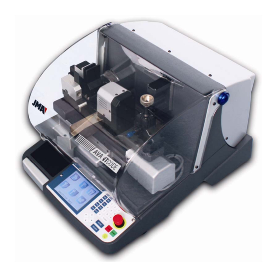
- Page 1 ELECTRONIC AVANTCODE USER GUIDE Version 0.0...
-
Page 2: Table Of Contents
3.2.2 USING THE FEEDER............................ 19 3.2.3 ASSEMBLY AND DISASSEMBLY OF THE AUTOMATIC CLAMP & FEEDER..........20 CONVERT THE AVANTCODE (STANDARD) INTO AN AVANTCODE (KEY FEEDER)......... 22 OPERATION MANUAL .......................... 23 CUT KEY ................................24 READ FILE............................... 33 EDIT FILE ................................. 40 4.4.1... - Page 3 LOCATING MALFUNCTIONS........................... 55 REPLACING THE FUSES ..........................56 REPLACING AND TENSING THE BELT ......................57 REPLACING THE AUTOMATIC CLAMP SET ....................58 REPLACING THE MILLING TOOL ........................58 REPLACING THE CARRIAGE SENSOR......................59 6.6.1 X AXIS ................................ 59 6.6.2 Y AXIS ................................ 59 REPLACING THE MOTOR ..........................
-
Page 4: Introduction And Overview
ID LABEL The AVANTCODE duplication machine has an ID label (Fig. 1) showing the serial number or machine registration number as well as the manufacturer’s name and address, EC label and year of manufacture. -
Page 5: Machine Installation And Characteristics
Make sure the emergency button is not pressed down, if it is, release it. When switched on, the JMA logo will appear alongside an internal test, then a few moments later, the carriages will move to their start-up position (if not in position already). - Page 6 This is a versatile machine that can be used both with standard clamps or the key feeder.
- Page 7 ID LABEL The AVANTCODE duplication machine has an ID label (Fig. 1) showing the serial number or machine registration number as well as the manufacturer’s name and address, EC label and year of manufacture.
- Page 8 Make sure the emergency button is not pressed down, if it is, release it. When switched on, the JMA logo will appear alongside an internal test, then a few moments later, the carriages will move to their start-up position (if not in position already). The machine is ready to use.
-
Page 9: Main Characteristics
JMA key catalogue, etc.) Use the AVANTCODE to create your own keys using the laser reader that comes included in the machine. Create and save your own new keys or enter the latest keys on the market into the machine without having to wait for the database to be updated. -
Page 10: Key Family
KEY FAMILY The AVANTCODE machine copies the following types of keys: • Flat keys. • Car keys. • FORD, ABLOY and MAILBOX keys. 2.4.1 KEY TERMS Diagram of a key showing the principle parts. (Fig.3) Collar Upper stop Lower stop... -
Page 11: Main Parts Of The Machine
MAIN PARTS OF THE MACHINE AVANTCODE (STANDARD) 2.5.1 Milling tool. Fig.4 Mill protector Standard clamp (MP1). Mechanized clamp lever. Clamp reading lever. X carriage. Y carriage. Protective shield. Keyboard. 10. Display screen. 11. Laser reader. 12. Shavings box. 13. Light. -
Page 12: Avantcode (Key Feeder)
2.5.2 AVANTCODE (KEY FEEDER) Fig.5 Milling Tool.(Fig.4). Mill protector. (Fig.4) Automatic clamp. Loading unit. Reader clamp. X carriage. Y carriage. Protective shield. Keyboard. 10. Display screen. 11. Laser reader. (Fig.4) 12. Shavings box. 13. Light. 14. Emergency button. 15. Mat. -
Page 13: Technical Information
TECHNICAL INFORMATION The main technical information is set out below: Motor..........Single phase 220V, 50 Hz, 0.25 Kw, 3000 rpm, 2.04 Amp. ∅ Milling......Widia 70 x 16 x 5.25 mm. Speed......1500 rpm. Clamps......Four faced. Movement....Via ball spindles activated by stepper motors on roller guides. -
Page 14: Machine Keyboard And Key Function
MACHINE KEYBOARD AND KEY FUNCTION The machine keyboard basically comprises a Touch Screen LCD, with some raised keys for correct use and an emergency button. The touch screen only uses icons and the raised keys are used in all of the various screens (Fig. 6) RAISED KEYS TOUCH SCREEN Emergency... -
Page 15: Cutting With Electricity
• The alphanumeric keys are used as follows: • Each number has its own key. • The letter keys work as follows: 1. To select the first letter, simply press it once. 2. Select the second letter on the keyboard by pressing the same key twice. 3. -
Page 16: Types Of Cut
Ideal: This is the most innovative vehicle key - the join between the bitting angles is automatically calculated by the AVANTCODE machine, to achieve variable angle combinations. This makes it easier to move the key and prolongs the life of the lock. -
Page 17: Accesories
2.10 ACCESORIES The AVANTCODE machine comes with a box of accessories for maintenance and repairs (Fig.10). The following accessories are included:: 18 mm spanner 2 mm Allen key Fuse: T4A 250V Mill blocking bar 2.5 mm Allen key Stylus Touch scream... -
Page 18: Configurations And Use
The AVANTCODE machine can have two separate configurations: 1. AVANTCODE (STANDARD): Clamp and reading clamps (Fig.11) Standard clamp Cutting clamp Reading clamp Fig.11 2. AVANTCODE (KEY FEEDER): Automatic and loading clamp and reading clamp (Fig.12) Automatic Reading Feeder clamp clamp... -
Page 19: Avantcode (Standard)
AVANTCODE (STANDARD) 3.1.1 USING THE “MP1” STANDARD CLAMP The machine comprises two clamps, a clamp and a reading clamp. The keyblank to be cut is placed in the clamp and the original key is placed in the reading clamp. The key is fastened in the standard “MP1” clamp designed to hold various key types. - Page 20 • Key stop. Once you have selected the side of the clamp, position the key lengthwise, bearing in mind the key stop. There are two types of stop, depending on the key model: Collar stop (C): This is the most common type. The key is stopped by mechanically blocking the clamp (Fig.14) Fig.14 Pointed tip (1, 2, 3): The key tip is produced using the tip stop supplied as an accessory,...
- Page 21 Fig.15...
-
Page 22: Cutting Cross Keys
Image of a clamp showing the slot numbering for producing the tips (Fig.16) • Side 1: Tips 1, 2, 3. • Side 2: Tips 1, 2. • Side 3: Tips 1, 2. • Side 4: Tips 1, 2. Fig.16 The instructions for correctly clamping the key in the standard clamp are shown in one of the information windows prior to cutting. -
Page 23: Mounting And Dismounting The Clamp
Fig.18 3.1.3 MOUNTING AND DISMOUNTING THE CLAMP • To remove the clamp: Loosen the setscrews (T1) until they extrude and remove the clamp from the dovetail (Fig.19). • To install the clamp: Place the clamp in the dovetail by pushing as far as it will go and then fix in place by fastening the setscrews (T1). -
Page 24: Avantcode (Key Feeder)
AVANTCODE (KEY FEEDER) 3.2.1 USING THE AUTOMATIC CLAMP Place the keys in the automatic clamp using the key feeder. The key leaves the feeder as the carriages move, the back of the key is positioned on the lower jaw of the automatic clamp and once in position, the upper jaw comes down to clamp the key. -
Page 25: Using The Feeder
3.2.2 USING THE FEEDER The loading system places the key in the automatic clamp when the machine carriages advance towards the feeder. The parameters of the key in the feeder are the same as that in the automatic clamp. You can place approximately 50 keys in the feeder. Points to remember when placing and adjusting keys in the feeder: Placing the key in the feeder. -
Page 26: Assembly And Disassembly Of The Automatic Clamp & Feeder
Adjusting the height of the loading system: The height of the key exit can be adjusted by raising or lowering the feeder. Follow these steps to do so: 1. Loosen the screws (T4), turn the screw (T5) raise or lower the feeder. 2. - Page 27 Fig.25 Fig.27 Fig.26 Fig.28...
-
Page 28: Convert The Avantcode (Standard) Into An Avantcode (Key Feeder)
CONVERT THE AVANTCODE (STANDARD) INTO AN AVANTCODE (KEY FEEDER) Converting the AVANTCODE (STANDARD) into an AVANTCODE (KEY FEEDER) only involves mounting the key box for automatic unloading. Step-by-step instructions for how to perform this conversion are set out below: Mounting the key box: •... -
Page 29: Operation Manual
OPERATION MANUAL The machine’s main menu is represented on the following screen: Each icon represents the following: • Cut key • Read key • Copy key • Edit files • Configuration • Maintenance... -
Page 30: Cut Key
CUT KEY This function is used to make a direct copy of the key. There are 4 different ways of cutting the key within this option, according to its: • File: Enter the file name or number (for a known file) for the key, or modify a file if one has already been created or edited. - Page 31 • Then enter the bits and press ENTER. CUT KEY File:476 Side: A Serial no.:1234567890 Bit code: ------------- • The following screen is for information only, it tells us which mill bit and clamp to use and how to secure the key in the clamp (See section 3.1.1). CUTTING INFO Milling tool FP16W...
- Page 32 Each option represents the following: Cut key: Start the cutting process. New bittings: Changes the number of key bittings. Number of keys: The number of keys to cut is defined. The machine will cut one key by default. If more keys are selected, a counter shows the number of keys that have been cut and the total to cut.
- Page 33 Manufacturer-model • Select the key manufacturer and press ENTER on the keyboard. (NB: The list of manufacturers is in alphabetical order) MANUFACTURER Arrow to move the cursor ABBES ABSA ABUS Arrow to move the cursor down • Press the CLEAR button on the keyboard or write the manufacturer initials to perform a quick search for the key.
- Page 34 • Once you have selected the model, its characteristics are displayed: profile, serial number, file and system. Arrow to move the cursor TE-8I Perfil Serie Ficha Sistema ..A 1234567890 ..B 1234567890 Arrow to move cursor down Ref. Number on main XXX/XXX Total number of references screen...
- Page 35 CUT KEY CUT KEY CUTTING INFO Cut key File :476 Milling tool FP16W Side: New bitting Clamp Serial no.: Clamp side Number of keys 1234567890 Clamp stop Bitting code: Cut - electricity ------- Cut type NORMAL Material: Steel – silver nickel...
- Page 36 Manufacturer – serial number • Select the key manufacturer and press ENTER on the keyboard. (Note: The manufacturer list is in alphabetical order) Manufacturer - Serial Arrow to move the cursor ABBES ABSA ABUS Arrow to move the cursor down •...
- Page 37 (NB: If the machine has a key feeder set up and you choose a double sided key or car key with a plastic bow an information screen will appear explaining that this key is incompatible with the application). WARNING!!!!! Incompatible cutting selection.
- Page 38 • Press the CLEAR button on the keyboard or write the manufacturer initials to perform a quick search for the key. Once you have selected the key, press ENTER on the keyboard. SEARCHING ..TESA • Then select the specific key to cut. TE-8I Profile Serial...
-
Page 39: Read File
• Once the key to cut has been selected, the following screens are the same as those that appear under the CUT => FILE option. (Section 4.1). CUT KEY CUT KEY File :476 Cut key CUTTING INFO Side: Milling tool FP16W Serial no.: 1234567890 New bitting Clamp... - Page 40 • Open the clear shield and place the key in the reading clamp, bearing in mind the corresponding position according to the information in the file. Close the shield and press ENTER on the keyboard. (NB: There must be no keys present in the feeder at this point. If there are, the machine will prevent you from reading the key.) READ KEY Place key in position...
- Page 41 (See section 4.1) CUT KEY Cut key New bitting Number of keys Cut - electricity Cut type NORMAL Material: Steel – silver nickel • Select the option and press the ENTER button on the keyboard.
- Page 42 4-3 COPIAR LLAVE This function is used to copy a key. The key can be cut using two distinct methods • Saved copy: Duplicates a key from a previously saved copy. Follow the steps described below: Escribir el nombre y pulsar ENTER Nombre de fichero -----------...
- Page 43 “Start copying”. Cuts the key that has been placed in the reading clamp. • Select “start copy” and press ENTER. COPY KEY Start cutting Enter correction Number of keys Save data • When you press ENTER the following window appears. COPY KEY Insert key for scanning START/STOP...
- Page 44 C OR RE C CION DE : +0.00 +0.00 ENTER/ESC • Enter the correction values to create the desired key: Correction values: The operator can modify the “depth” and “spacing” parameters. Changing the depth values (positive or negative) means raising or lowering all of the encryption (Fig.32) Fig.32 The entire encryption is moved to the left or to the right (towards or away from the tip...
- Page 45 COPY KEY Start cutting Enter correction Number of keys Save data • Select “start copy” and press ENTER. Number of keys COPY KEY Start cutting Enter correction Number of keys Save data • Press the ENTER button. Open the clear shield, place the key in the reading clamp and close the shield.
-
Page 46: Edit File
EDIT FILE The machine comes equipped with a key editor which allows you to create and save your own keys, either because you are a lock manufacturer with special keys, because you master keys, or because a new key has been released onto the market which was not included in the machine. - Page 47 Milling tool FP16 corresponding reference here. Clamp (NB: The Avantcode cannot use any milling tools that have not been specially designed for it and supplied by JMA) Key stop • Clamp: Standard clamp reference. The machine comes equipped with the MP1 Clamp stop clamp.
- Page 48 EDIT FILES Spaces: ---- ---- ---- ---- ---- ---- And finally, Bases: is the width of the blade supporting the bitting on the key. EDIT FILES Bases: ---- ---- ---- ---- ---- ---- Example of how to complete tables 3, 4 and 5 (Fig.34): Spaces Entry angle 4 .2...
- Page 49 EDITING FILES Symbol/Depth: 01/710 03/610 02/660 04/460 When entering the data, leave the symbol field blank and press ENTER. The program will understand that the depth registration process has finished and will continue to the next table. Complete the next table with the distances between the pin axes. The number of data to enter is determined by the number of supports defined in the previous file.
-
Page 50: Modify File
4.4.2 MODIFY FILE Once you have created the files, you can then modify and readjust the values until you achieve the desired key. • Starting from the main menu, the sequence to reach this point is as follows: Modify file •... -
Page 51: Delete File
2. AVANTCODE (KEY FEEDER): Automatic clamp and feeder and reading clamp. Each time the AVANTCODE configuration is changed from STANDARD to KEY FEEDER or vice- versa, you need to calibrate the machine prior to performing any operation (cutting, reading or copying a key). - Page 52 “Cut key” option (See section 4.3.). If it is not calibrated, the first key will be cut with a calibration error, however the following keys will be cut correctly. Configure the AVANTCODE (KEY FEEDER): Adjust the feeder: “Calibrate feeder”, but you do not have to calibrate the reader “Calibrate reader”.
- Page 53 Area to Area to clean clean clean clean Avantcode (Key Feeder) Avantcode (Standard) Fig.36 Fig.37 The steps to follow to calibrate the clamp, reading clamp and feeder are as follows: CALIBRATE MILLING TOOL 1. Select the Calibrate milling tool icon.
- Page 54 4. Close the shield and press START. 5. A “processing” message appears. 6. Once the cycle completes, the following message appears for a moment, and then the screen returns to the calibration menu. Saving information!!! Once the milling tool has been calibrated, you have to calibrate the reading clamp. CALIBRATE READER 1.
- Page 55 8. Continue as follows (Fig.39): • If X is not 0, loosen the screw (T12) and use the 2 Allen key to advance or go back according to the directions indicated on the display, by turning the screw (T13). (NB: Turning the screw (T13) a quarter turn produces a 13 hundredths of a millimeter movement). •...
- Page 56 Saving information!!!
-
Page 57: Maintenance
MAINTENANCE This function is used to check the various machine values, such as: • Manufacturer values • Data connection • Information • Speed • Password • Other options 4.6.1 Manufacturer values This function allows you to restore the manufacturer’s settings. A warning message is displayed on the screen, telling you that you will lose all the information stored in the memory. - Page 58 4.6.6 Other options Other machine functions: • Language The various languages in which the machine can be used are displayed These languages are: Spanish English French German Italian Portuguese Once you have selected the language, press ENTER or ESCAPE to leave the menu. •...
- Page 59 • Touch screen Allows you to activate, deactivate or calibrate the touch screen. Select the option and press ENTER, otherwise ESCAPE to EXIT. • Save energy You can select 3 energy levels, low, medium and high, with this function. Select the option and press ENTER, otherwise ESCAPE to EXIT.
-
Page 60: Pc Operation
PC OPERATION In this application, the machine enters slave mode, i.e. it is commanded by a PC. The machine must be connected using a serial port. (See section 2.5, Fig.5). If you press the “PC COMMUNICATION” function again, the machine will return to its normal operating mode. -
Page 61: Cleaning And Safety
CLEANING AND SAFETY We recommend you follow these steps when cleaning: • Keep the operational parts of the machine as clean as possible, remove shavings using the brush • Do not use compressed air to clean the working area with shavings, as this will push them into the operating parts. - Page 62 LOCATING MALFUNCTIONS MALFUNCTION PROBABLE CAUSE The machine is turned on, but Emergency button pressed down the display is blank The display-keyboard is broken The cable from the display screen to the control board is badly connected The optical reader is not working Dirt on the glass conical part of the laser reader The cable from the reader to the control board is badly connected The optical reader is broken...
- Page 63 REPLACING THE FUSES If the machine fails to start when switched on, check the fuses. The machine has two fuses: one is located in the back and the other in the machine control board. Follow these steps to change the fuse: 1.
- Page 64 REPLACING AND TENSING THE BELT Follow these steps to check the tension of the belt or to replace it: 1) Turn the machine off at the main switch and disconnect the power cable. 2) Unscrew the 6 screws fastening the “motor casing” and remove it. The screws are on the right and left sides, the upper and lower sections.
- Page 65 REPLACING THE AUTOMATIC CLAMP SET Proceed as follows to replace the set of clamps: 1) Once you have removed the automatic clamp, unfasten the two screws (T19) and remove the set of clamps (Fig.45). 2) Insert the new set of clamps, making sure that they are supported against the inner support.
- Page 66 Fig.47 Fig.48 REPLACING THE CARRIAGE SENSOR 6.6.1 X AXIS 1) Turn the machine off at the main switch and disconnect the power cable. 2) Unfasten the two cover screws (T24) and the two screws holding the sensor (T25). (Fig.49, Fig.50). 3) Change the sensor and tighten the screws holding the sensor and the cover.
- Page 67 Fig.51...
- Page 68 REPLACING THE MOTOR 1) Turn the machine off at the main switch and disconnect the power cable. 2) Unscrew the 6 screws fastening the “motor casing” and remove it. The screws are on the right and left sides, the upper and lower sections. 3) Loosen and remove the belt (see section 6.3).
- Page 69 Fig.57 Fig.56 Fig.58 REPLACING THE LEDS 1) Turn the machine off at the main switch and disconnect the power cable. 2) Unscrew the 6 screws fastening the “rear motor casing”. The screws are on the right and left sides, the upper and lower sections. 3) Release the two power strip cables (P11), by releasing the two screws (T29).
- Page 70 Waste is understood to mean any substance or object produced by human or natural activity that has been or is to be thrown away. PACKAGING • As the packaging in which the AVANTCODE machine is supplied is cardboard, it can be recycled. • It can only be disposed of in the special cardboard containers.
- Page 71 SUPPORT Alejandro Altuna provides technical support to all AVANTCODE machine customers. To ensure complete operator and machine safety, any operations that are not described in this manual should only be performed by the manufacturer or technical support team. If you have any questions about using the machine, please contact the address specified on the back of the manual.
- Page 72 AVN-193 AVN-194 AVN-195 AVN-6 AVN-171 AVN-160 AVN-2 AVN-7 AVN-1...
- Page 73 AVN-193 AVN-198 AVN-196 MPAT AVN-197 AVN-195 AVN-197 AVN-174...
- Page 74 AVN-84 AVN-67 MPAT AVN-67 AVN-136...
- Page 75 AVN-136 GOR-520 AVN-196 AVN-140...
Need help?
Do you have a question about the AVANTCODE and is the answer not in the manual?
Questions and answers