
Related Manuals for MICRO-EPSILON surfaceCONTROL SC2500


Summary of Contents for MICRO-EPSILON surfaceCONTROL SC2500
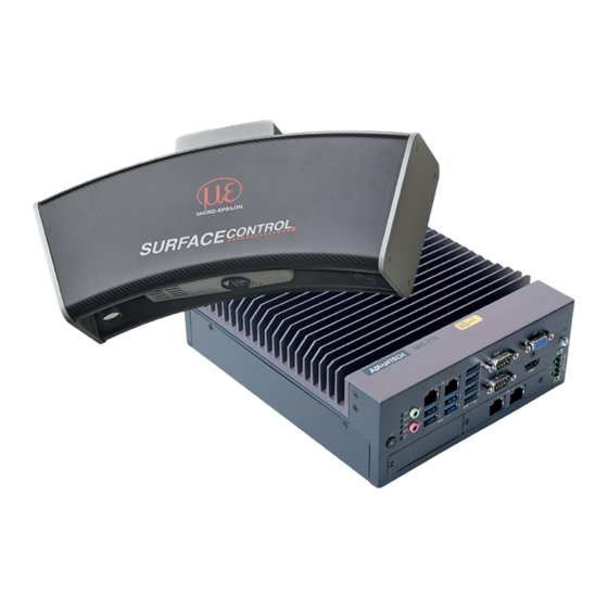
- Page 1 Operating Instructions surfaceCONTROL 3D SC2500 / SC2510 SC2500-300 SC2510-300 SC2500-400 SC2510-400 SC2500-575 SC2510-575...
- Page 2 MICRO-EPSILON MESSTECHNIK GmbH & Co. KG Koenigbacher Str.15 94496 Ortenburg/Germany Tel. +49 (0) 8542 / 168-0 Fax +49 (0) 8542 / 168-90 e-mail info@micro-epsilon.com www.micro-epsilon.com...
-
Page 3: Table Of Contents
Contents Safety ............................5 Symbols Used ..............................5 Warnings ................................5 Notes on CE Marking ............................6 Intended Use ..............................6 Proper Environment ............................6 Light Source ..........................7 Functional Principle, Technical Data ..................8 Short Description ............................. 8 3.1.1 Measuring Principle ........................ - Page 4 surfaceCONTROL 3D SC2500 / SC2510...
-
Page 5: Safety
Safety Safety System operation assumes knowledge of the operating instructions. Symbols Used The following symbols are used in these operating instructions: Indicates a hazardous situation which, if not avoided, may result in minor or moderate injury. Indicates a situation that may result in property damage if not avoided. Indicates a user action. -
Page 6: Notes On Ce Marking
Safety Notes on CE Marking The following apply to the surfaceCONTROL 3D 25x0 measuring system: - EU Directive 2014/30/EU - EU Directive 2011/65/EU Products which carry the CE mark satisfy the requirements of the EU directives cited and the relevant applicable harmo- nized European standards (EN). -
Page 7: Light Source
Light Source Light Source The surfaceCONTROL 3D 25x0 sensor works with an LED lighting unit. Measurement is performed using blue light at the dominant 462 nm wavelength. The sensor is included in risk group 2 according to EN 62471: 2008. Do not look into the lens. -
Page 8: Functional Principle, Technical Data
- surfaceCONTROL 3D 25x0 is characterized by a compact design and highly accurate measurements while at the same time achieving high throughput of 3D points. - Data are output via Gigabit Ethernet. GigE Vision compatibility allows the sensor to be integrated in different ways: ƒ Software provided by Micro-Epsilon ƒ Software by third parties ƒ SDK... -
Page 9: Technical Data
Material Carbon, aluminum, plastics Weight 7.0 kg (without controller) Control and display elements 2 LEDs on each camera (for device status, power, data transmission) Sensor SDK Micro-Epsilon 3D Sensor-SDK 3D evaluation software Micro-Epsilon 3DInspect Functional extension 3DInspect 3DInspect 3DInspect Automation... -
Page 10: Control And Indicator Elements
Functional Principle, Technical Data SC2500 controller 16 GB Supply voltage 9 ... 36 V DC Current consumption 3 … 12.4 A Digital interfaces 4 x Gigabit Ethernet (GigE Vision / GenICam) / USB 2.0 (sensor control) / PROFINET / EtherCAT / EtherNet/IP Connection 4-pin supply terminal strip, 4 x Ethernet... - Page 11 Functional Principle, Technical Data Power LED power Off, supply voltage available Green Ready to use LED HDD Meaning No access to hard drive Read and write access to hard drive LED LAN 1 / 2 Meaning Link LED (left): Constant orange Gigabit Ethernet connection established Constant green 100 Mbit Ethernet connection established...
-
Page 12: Delivery
Delivery Delivery Unpacking/Included in Delivery - 1 Sensor surfaceCONTROL 3D 25x0 - 1 Controller SC2500 - 1 Cable harness/5 m/standard for surfaceCONTROL - 1 Assembly Instructions - 1 Calibration protocol - 1 Table power pack sensor - 1 Ethernet patch cable (Cat6A, grey, 5 m) - 1 DIN rail mounting kit for controller - 1 Power supply cable (4-pol. -
Page 13: Installation And Assembly
Installation and Assembly Installation and Assembly Sensor All components of the sensor are preassembled at the factory. Refer to the dimensional drawings for the mounting dimensions. Ensure careful handling during installation and operation. Damage to or destruction of the sensor Before connecting the sensor to the power supply and the system computer, mount it on a tripod or robot with the appropriate mounting adapters. - Page 14 Installation and Assembly 103 (4.06) 400 (15.75) 300 (11.81) 350 (13.78) 260 (10.24) 660 (25.98) 760 (29.92) 860 (33.86) 450 (17.72) 340 (13.39) Fig. 6 Dimensional drawing of surfaceCONTROL 3D SC25x0-400, dimensions in mm (inches) surfaceCONTROL 3D SC2500 / SC2510 Page 14...
- Page 15 Installation and Assembly 103 (4.06) 575 (22.64) 435 (17.13) 500 (19.69) 375 (14.76) 950 (37.40) 1100 (43.31) 1250 (49.21) 650 (25.59) 495 (19.49) Fig. 7 Dimensional drawing of surfaceCONTROL 3D SC25x0-575 sensor, dimensions in mm (inches) surfaceCONTROL 3D SC2500 / SC2510 Page 15...
-
Page 16: Mounting Adapter
Installation and Assembly Mounting Adapter The sensor is attached either to a tripod, a robot or a portal. For mounting the sensor on a tripod or a robot, corresponding mounting adapters (matt black anodized) are provided as separate accessories, see Chap. -
Page 17: Sc2500 Controller
Installation and Assembly SC2500 Controller Mounting adapters enable wall mounting of the SC2500 controller; these are included in the scope of delivery. 250 (9.84) 224 (8.82) 192 (7.56) Fig. 9 Dimensional drawing of SC2500 controller with mounting adapter, dimensions in mm (inches) Remove the plastic covers from the preferred mounting surface of the controller. -
Page 18: Electrical Connections
Installation and Assembly Electrical Connections 5.4.1 Connection Diagram Sensor SC2500-x Table power 19V Cable harness/5 m/ standard for surfaceCONTROL LAN-cable with 2x RJ45 male connector DefMap3D Controller sC2500 3DInspect 5.4.2 surfaceCONTROL 3D 2500 Sensor 5.4.2.1 General All connectors of the sensor are located in the connector panel on the rear side. Fig. -
Page 19: Sensor Control (Usb)
Installation and Assembly 5.4.2.3 Sensor Control (USB) Signal USB D+ USB D- USB VCC Fig. 13 Pin assignment connector USB port The cable shield is connected to the connector housing. The sensor is configured and controlled via the available USB 2.0 interface. Use only the supplied USB cable. A 4-pin LEMO PushPull connector is used on sensor side. -
Page 20: Surfacecontrol 3D 2500 Controller
Installation and Assembly 5.4.3 surfaceCONTROL 3D 2500 Controller 5.4.3.1 General All connections for the controller are located on the front. Fig. 16 Rear view of sensor with connectors Ethernet port, PC connection Sensor control Ethernet port Camera 1 and 2 Power supply 5.4.3.2 Supply Voltage (Power) -
Page 21: Gigabit Ethernet Connection
Installation and Assembly 5.4.4 Gigabit Ethernet Connection The Ethernet connection is the standard connection to the PC. The sensor supports transmission at 1 Gbit/s. Four 8-pin RJ45 sockets are installed in the housing. We recommend you use the optional Cat6A category patch cables with cable lengths of 2 m, 5 m or 10 m for the Ether- net connection. -
Page 22: Initial Operation
Installation and Assembly Initial Operation The sensor and the controller may only be connected to peripherals when they do not carry power, that is, only when the supply voltage has been switched off. Mount the sensor according to the assembly instructions, see Chap. -
Page 23: Operation
Operation Operation Turning On Switch on the power supply (24 VDC) on the controller. Press the Power button on the controller. Power The Power LED on the controller is illuminated red if the power supply is sufficient, and green after pressing the Power button. -
Page 24: Connecting Surfacecontrol 3D 25X0 To The Pc
Operation 6.3.2 Connecting surfaceCONTROL 3D 25x0 to the PC To connect surfaceCONTROL 3D 25x0 via Ethernet to the PC, proceed as follows: 1. Complete the installation of the software. 2. Connect surfaceCONTROL 3D 25x0 to the PC using the Ethernet interface. 3. -
Page 25: Positioning Of Sensor And Test Object
Operation 6.4.3 Positioning of Sensor and Test Object 6.4.3.1 General Note the following instructions for optimum positioning of the sensor and test object. - Observe an optimum distance between the sensor and the surface of the test object, see Chap. 3.2. - Page 26 Fig. 22 Lateral tilt, tilted around the y-axis, distance correct The screens shown were created with the 3DInspect software from Micro-Epsilon. Further details can be found in the respective operating instructions of the software provided by Micro-Epsilon or in the GenICam parameter description, see Chap.
-
Page 27: Exposure
Operation 6.4.4 Exposure The projected fringe pattern should be well recognizable over the entire measurement plane (not too light/dark) in order to avoid overdriven and underdriven pixels. The Exposure time parameter enables you to adjust the exposure. In the main view, switch from the 3D View to the Image data. Switch to the Data acquisition tab. -
Page 28: Interferences
The distribution of gray values in the histogram should be approximately uniform with the projected pattern. The number of overexposed and underexposed pixels should be reduced to a minimum. The screens shown were created with the 3DInspect software from Micro-Epsilon. Interferences 6.5.1... -
Page 29: Surface Roughness And Texture
Operation 6.5.6 Surface Roughness and Texture Surface roughnesses of the order of 5 µm and more as well as textures on the surface result in increased “surface noise”. In addition, direct reflections of the projected light can also occur on grinding marks or small scratches on the surface. -
Page 30: Disclaimer
MICRO-EPSILON or to your distributor / retailer. MICRO-EPSILON undertakes no liability whatsoever for damage, loss or costs caused by or related in any way to the product, in particular consequential damage, e.g., due to... -
Page 31: Appendix
Appendix | Accessories Appendix Accessories Cable harness/5 m/standard Cable harness for connecting a sensor to the controller, for surfaceCONTROL contains the cables for data transmission of both cameras and sensor control; length 5 m, total cable diameter: approx. 6.8 mm, minimum bending radius with continuous movement: 10x cable diameter. - Page 32 Appendix | Optional Accessories Tripod set Tripod for mounting and alignment of surfaceCONTROL 3D sensors, including tripod bag, ground spreader, tripod head, tripod adapter Column stand Column stand for mounting and alignment of surfaceCON- TROL 3D sensors surfaceCONTROL 3D SC2500 / SC2510 Page 32...
-
Page 33: A 2.1 Drawings Of Mounting Adapter
Appendix | Optional Accessories A 2.1 Drawings of Mounting Adapter A 2.1.1 X95/Dovetail Mounting Adapter The X95/dovetail mounting adapter is used to mount the sensor on a quick release plate with a dovetail profile of size 050/87 or to the profile system X95 of the manufacturer Linos (Qioptiq). Fig. -
Page 34: A 3 Genicam Surfacecontrol Parameters
Appendix | GenICam surfaceCONTROL Parameters GenICam surfaceCONTROL Parameters Details about setting the parameters are available in the software description, see 3D-View operating instructions. Parameter Description Observe the notes below if you operate the sensor with a third party library for GenICam/GigE Vision: - The library must support GigE Vision 2.1. - Page 35 Appendix | GenICam surfaceCONTROL Parameters | Version 1.5 Name Description Documentation Text Device Control DeviceTemperatureSelector Selects the location within Serves as a switch for the temperature sensor to be read: the device, where the Internal - internal sensor temperature temperature will be mea- Cpu - processor temperature sured.
- Page 36 Appendix | GenICam surfaceCONTROL Parameters | Version 1.5 Name Description Documentation Text ImageOffset[SourceSelector] 2D Mode components Offset for the gray values of the [Amplitude], [Curvature] and [Base] [ComponentSelector] only: Offset components. Acquisition Control AcquisitionMode Sets the acquisition mode Sets the mode for 3D image acquisition. of the device.
- Page 37 Appendix | GenICam surfaceCONTROL Parameters | Version 1.5 Name Description Documentation Text Measurement Control GraycodeThreshold Minimum allowed pattern Only pixels whose gray value difference between the bright and dark contrast in the graycode images is equal to or greater than the limit value set are used for the images (for 3D reconstruc- calculation.
- Page 38 Appendix | GenICam surfaceCONTROL Parameters | Version 1.5 Name Description Documentation Text Scan3dControl Scan3dCoordinateSelector Selects the individual co- Serves as a switch for the selected 3D coordinate. ordinates in the vectors for 3D information/transfor- mation. Scan3dCoordinateScale Scale factor when trans- Defines the distance between points in the measuring field [mm] in x [Scan3dExtractionSelector] forming a pixel from rela-...
- Page 39 Appendix | GenICam surfaceCONTROL Parameters | Version 1.5 Name Description Documentation Text Event Control EventFrameTriggerData Category that contains all This event is triggered when a trigger has been initiated. the data features related to the FrameTrigger Event. EventFrameTrigger Returns the unique Iden- This event is triggered when a trigger has been initiated.
- Page 40 - 1: Error Sensor Hardware: An error occurred in a hardware compo- nent in the sensor. Contact Micro-Epsilon. - 2: Error Sensor Acquisition: An error occurred during data acquisition in the sensor. Contact Micro-Epsilon.
- Page 42 MICRO-EPSILON MESSTECHNIK GmbH & Co. KG Königbacher Str. 15 · 94496 Ortenburg/Germany Phone +49 8542 / 168 0 · Fax +49 8542 / 168 90 X9751439-A012012MSC info@micro-epsilon.de · www.micro-epsilon.de Your local contact: www.micro-epsilon.com/contact/worldwide/ MICRO-EPSILON MESSTECHNIK...
Need help?
Do you have a question about the surfaceCONTROL SC2500 and is the answer not in the manual?
Questions and answers