
Subscribe to Our Youtube Channel
Related Manuals for MICRO-EPSILON induSENSOR EDS Series


Summary of Contents for MICRO-EPSILON induSENSOR EDS Series
- Page 1 Instruction Manual induSENSOR, EDS EDS-75-S EDS-260-Z EDS-100-S/F EDS-300-S/F/Z EDS-160-S/F EDS-370-Z EDS-200-S/F EDS-400-S/F/Z EDS-220-Z EDS-500-S EDS-250-S/F EDS-630-S/F...
- Page 2 Long-Stroke sensors, Series EDS...
-
Page 3: Table Of Contents
Contents Safety ............................5 Symbols Used ..............................5 Warnings ................................5 Notes on CE Identification ..........................6 Proper Use ............................... 6 Proper Environment ............................7 Functional Principle, Technical Data ..................8 Measuring Principle ............................8 Structure ................................9 Technical Data ............................... 10 Delivery ........................... - Page 4 Operation ..........................33 Operation and Maintenance ....................33 Warranty ..........................34 Decommissioning, Disposal ....................34 Appendix ..........................35 induSENSOR, EDS...
-
Page 5: Safety
Safety The handling of the system assumes knowledge of the instruction manual. Symbols Used The following symbols are used in this instruction manual: Indicates a hazardous situation which, if not avoided, may result in minor or moder- ate injury. Indicates a situation which, if not avoided, may lead to property damage. Indicates a user action. -
Page 6: Notes On Ce Identification
Products which carry the CE mark satisfy the requirements of the quoted EU directives and the European standards (EN) listed therein. The EC declaration of conformity is kept available according to EC regulation, article 10 by the authorities responsible at MICRO-EPSILON MESSTECHNIK GmbH & Co. KG Königbacher Straße 15 94496 Ortenburg / Germany The measuring system is designed for use in industry and satisfies the requirements. -
Page 7: Proper Environment
Proper Environment - Protection class for sensor ƒ Sensor rod IP 69K ƒ Electronics: IP 67 - Operating temperature: -40 °C up to +85 °C (-40 up to +185 °F), R = 500 Ohm - Storage temperature: -40 °C up to +100 °C (-40 up to +212 °F) - Humidity: 5 - 95 % (non-condensing) - Ambient pressure:... -
Page 8: Functional Principle, Technical Data
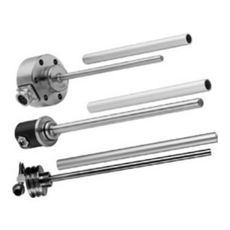
Functional Principle, Technical Data Measuring Principle The eddy current long stroke displacement sensors transform a linear motion (for example piston position in hydraulic cylinders) into a linear, electrical signal. An aluminium tube, moving concentrically around a sensor rod, is used as target. Energy is transferred from the coil by inducing of eddy currents in the aluminium tube and it is detuned as a result. -
Page 9: Structure
Structure A coil is mounted inside the sealed rod, protected against environmental influences. The micro-electronics is integrated in the sensor housing. A pressure-proof, stainless steel housing is available as an option. The sen- sors are used for measuring lengths from 100 to 630 mm. Electrical connection: - Connector 4-pins, type Amphenol C164P compact (Model EDS-...-S...) - Connector 7-pins, type Binder 712 (Model EDS-...- S ...7...) -
Page 10: Technical Data
Technical Data Model -100 -160 -200 -220 -250 -260 -300 -370 -400 -500 -630 Connections S, F S, F S, F S, F S, F, Z S, F, Z S, F Measuring range Linearity ±0.3 % FSO mm 0.23 0.48 0.66 0.75 0.78... - Page 11 Model -100 -160 -200 -220 -250 -260 -300 -370 -400 -500 -630 Connections S, F S, F S, F S, F S, F, Z S, F, Z S, F Sensor material V4A-Steel 1.4571 Tube material AlMgSi, enodized EDS-...-S EDS-...-F 1260 1270 1300 1320 1350 1560...
-
Page 12: Delivery
Delivery Unpacking Do not take and hold the sensor at the sensor rod. Check for completeness and shipping damage immediately after unpacking. Sensor housing The delivery of an eddy current long stroke displacement sensor includes: 1 Eddy current long stroke displacement sensor 1 O-ring (mounted on sensor) 1 Measuring tube 1 Test report... -
Page 13: Installation And Assembly
Mount the measuring tube in the piston by means of pressing or glueing. Spot clamping is not permissible. The specified technical data are valid only if the measuring tube is used supplied by MICRO-EPSILON! induSENSOR, EDS Page 13... - Page 14 Fig. 2 Zero point of the measuring tube, EDS- ... -S Fig. 3 Zero point of the measuring tube, EDS- ... -F Measuring range Dimension a 15 (0.59) 20 (0.79) 20 (0.79) 20 (0.79) 20 (0.79) 20 (0.79) 20 (0.79) Fig.
-
Page 15: Sensor Mounting
Sensor Mounting 4.3.1 Model EDS- ... -S Mount the sensor in the cylinder with a mounting ring (Appendix), see Fig. 12 and six cylinder head bolts (M5x10). Sealing is effected at the sensor shaft by means of an O-ring supplied. Displacement Sensor rod Cylinder... - Page 16 Use a connection piece for moun- ting, see Fig. 6. The bushing must be congruent with the connector for models with radial connector. Bushing for connector Fig. 6 Mounting of an induSENSOR, model EDS- ... -S Use an extractor for dismounting, Fig.
- Page 17 Dimensional drawing, model EDS- ... -S min 30 (1.18) Alu tube I Sensor rod L 32.5 (1.28) +0.1 -0.1 (.16 (.32 +0.1 -0.004 Fig. 8 induSENSOR with axial connector, model EDS- ... -SA7 - I, measuring range: 75 (2.95) / 100 (3.94) / 160 (6.29) / 200 (7.87) / 250 ( 9.84) / 300 (11.81) Measuring Sensor rod L Alu tube I Alu tube d...
- Page 18 Fig. 9 induSENSOR with radial connector, model EDS- ... -SR7 - I, measuring range: 75 (2.95) / 100 (3.94) / 160 (6.29) / 200 (7.87) / 250 (9.84) / 300 (11.81) EDS-xxx-S-Sx-I (1.2) EDS-xxx-S-Sx7-I (2.0) Dimensions in mm, not to scale 1) Previous version no longer available.
- Page 19 min 30 (1.18) Alu tube I Sensor rod L 32.5 (1.28) +0.1 -0,1 (.16 (.63 +0.1 -0.004 Fig. 10 induSENSOR with axial connector, model EDS- ... -SA7 - I, measuring range: 400 (15.74) / 500 (19.69) / 630 (24.80), dimensions in mm (inches), not to scale Dimension Tolerance µm EDS-xxx-S-Sx-l...
- Page 20 Fig. 11 induSENSOR with radial connector, model EDS- ... -SR7 - I, measuring range: 400 (15.74) / 500 (19.69) / 630 (24.80) EDS-xxx-S-Sx-I 31 (1.2) EDS-xxx-S-Sx7-I 51 (2.0) Dimensions in mm (inches), not to scale 1) Previous version no longer available. induSENSOR, EDS Page 20...
- Page 21 ø80.0 (ø3.15) 12.0 (.47) ø6.2 (ø.24) +0.05 +0.002 ø34.0 (ø1.34 +0.1 +0.004 ø31.0 (ø1.22 ø16.0 (ø.63) ø55.0 (ø2.17) 30.0 ° Fig. 12 Mounting ring, model EDS- ... -S, dimensions in mm (inches), not to scale induSENSOR, EDS Page 21...
-
Page 22: Model Eds
4.3.2 Model EDS- ... -F The sensor is mounted in the cylinder by means of cylinder head bolts (6 x M8). The sealing is effected at the sensor shaft by means of an O-ring supplied. Cylinder head Sensor rod Cylinder Piston bolt M8 Displacement... - Page 23 Dimensional drawing, model EDS- ... -F ø29 (1.14 dia) Alu tube I Sensor rod L O-ring groove 20.0 35.0 (0.79) (1.38) Measuring Sensor rod Alu tube range ø63.0 (2.48 dia.) 100 (3.93) 140 (5.51) 10 (0.39) 140 (5.51) 16 (0.63) ø80.0 (3.15 dia.) 160 (6.29) 200 (7.87)
-
Page 24: Model Eds
4.3.3 Model EDS- ... -Z The sensor is fixed in the cylinder with a grub screw and clamped from the back panel. Sealing is effected at the sensor shaft by means of an O-ring. Feed the connecting wires in able duct outwards and connect them with the mounting plug. Grub screw Back panel Sensor rod... - Page 25 Dimensional drawing, model EDS- ... -Z Alu tube I 33 (1.3) 21(0.82) (0.47) 1 x 45 ° Sensor rod L Measuring Sensor rod Alu tube Fig. 16 induSENSOR with axial wires, range model EDS- ... -Z, dimensions in mm (inches), 220 (8.66) 252 (9.92) 10 (.39) 250 (9.84...
- Page 26 Use an extractor pipe for dismounting, see Fig. Female thread in the extractor pipe: M24 x 1.5 Proceeding: 1. Unplug the adapter. 2. Release the grub screw 3. Screw on the extractor pipe on the sensor shaft and pull out the sensor from the cylinder. Extractor pipe Fig.
-
Page 27: Power Supply And Display/Output Device
Power Supply and Display/Output Device 4.4.1 Model EDS- ... -S The power supply and the signal output are effected through 7-pin connector on the sensor’s electronic housing. The pin assignment is shown, see Fig. Assignment Color Pin 2 is connected with C703-5 pin 4 on the electronics board. - Page 28 EDS-...-S can be inserted as an option for adap- 18...30 VDC tation of the power loss to high ambient temperatures, see Chap. 4.4.4. Fig. 20 Signal monitoring with amperemeter EDS-...-S If the signal is monitored with a voltmeter 18...30 VDC the load resistor R is sized to give the de- sired output voltage U...
-
Page 29: Model Eds
4.4.2 Model EDS- ... -F Power supply and signal output are effected through the 5-contact connector on the sensor’s electronic housing. The pin assignment is shown, see Fig. Assignment A 5-pin cable socket for the user-side as- Connector sembly of your own connecting cable is Type CA02COM-G14S Power supply + (18 ... -
Page 30: Model Eds
EDS-...-F If the signal is monitored with a voltmeter the load resistor R is dimensioned in ac- cordance with the desired output voltage 18...30 VDC Formula: U Signal Fig. 24 Signal monitoring with load resis- tor and voltmeter 4.4.3 Model EDS-...-Z Power supply and signal output are effected through the 4-contact connector on the hydraulic cylinder. - Page 31 EDS-...-Z can be inserted as an option for adapta- tion of the power loss to high ambient temperatures, see Chap. 4.4.4. Fig. 26 Signal monitoring with amperemeter EDS-...-Z If the signal is monitored with a voltmeter the load resistor R is dimensioned in ac- cordance with the desired output voltage Formula:...
-
Page 32: Load Resistor, Maximum Operating Temperature
4.4.4 Load Resistor, Maximum Operating Temperature The sensors are connected according to the pin assignment shown, see Fig. 18 et seq. (all series). Notice the different criterias: = (U - 10 V) / 20 mA L max = 82.5 * 1/V * U - 1625 Ohm L min = 150 °C - 3.3 °C/V * U... -
Page 33: Operation
Imperfect measuring tube guiding can lead to increased wear and premature defects. The warranty and all liability claims are null and void if the device is worked on by unauthorized persons. Repairs are to be made exclusively by MICRO-EPSILON. induSENSOR, EDS... -
Page 34: Warranty
No other claims, except as warranted, are accepted. The terms of the purchasing contract apply in full. MICRO-EPSILON will specifically not be responsible for eventual consequential damages. MICRO-EPSILON always strives to supply the customers with the finest and most advanced equipment. Development and refinement is therefore performed continuously and the right to design changes without prior notice is accordingly reserved. -
Page 35: Appendix
Appendix Accessories DD241 PC (10) Digital process readout, power supply: 12 ... 30 VDC, sensor supply: 10 ... 26 VDC DD245 PC (10) Digital process readout, power supply: 18 ... 30 VDC, sensor supply: 18 VDC+/- 10 %, max. 350 mA, digital output: RS422; analog output: 3x programmable, 0 ... - Page 36 X9751051-B081115GBR MICRO-EPSILON MESSTECHNIK...
Need help?
Do you have a question about the induSENSOR EDS Series and is the answer not in the manual?
Questions and answers