
Related Manuals for MICRO-EPSILON surfaceCONTROL 2500


Summary of Contents for MICRO-EPSILON surfaceCONTROL 2500
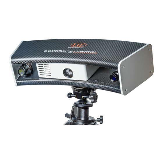
- Page 1 Operating Instructions surfaceCONTROL 2500 surfaceCONTROL 2500-360 surfaceCONTROL 2500-360/ST surfaceCONTROL 2500-500 surfaceCONTROL 2500-500/ST surfaceCONTROL 2500-720 surfaceCONTROL 2500-720/ST...
- Page 2 INB Vision AG Brenneckestr. 20 ZENIT Technology Park II 39118 Magdeburg / Germany Tel. +49 (0) 391 / 6117-300 Fax +49 (0)391 / 6117-301 info@inb-vision.com www.inb-vision.com...
-
Page 3: Table Of Contents
Commissioning .............................. 18 Displays ................................. 18 Operating Programs ............................18 Installation ..............................18 6.4.1 Requirements ..........................18 6.4.2 Connecting surfaceCONTROL 2500 / 2500/ST to the PC ............19 6.4.3 Network............................19 6.4.3.1 Components ........................ 19 6.4.3.2 Design ......................... 19 6.4.3.3 Configuration ....................... - Page 4 Accessories and Spare Parts ....................24 A 1.1 Recommended Accessories, Spare Parts ....................24 A 1.2 Optional Accessories ............................. 24 A 1.3 Drawings Mounting Adapters ........................25 A 1.3.1 X95/Dovetail Mounting Adapter ....................25 A 1.3.2 47° Dovetail Mounting Adapter ....................25 surfaceCONTROL 2500...
-
Page 5: Safety
> Damage to or destruction of the sensor The sensor housing may only be opened by authorized persons. > Damage to or destruction of the sensor Only plug in or disconnect attached devices when disconnected from the power supply. surfaceCONTROL 2500 Page 5... -
Page 6: Notes On Ce Marking
The EU Declaration of Conformity is available to the responsible authorities according to EU Directive, article 10. Intended Use - The surfaceCONTROL 2500 measurement system is designed for use in industry and laboratories. It is used for ƒ non-contact optical measurement of diffuse reflective surfaces ƒ... -
Page 7: Proper Environment
10 … 90 % (non-condensing) llumination The surfaceCONTROL 2500 sensor has an LED lighting unit with a high-power LED of wavelength 462 nm (blue), 528 nm (green) or 612 nm (red) depending on the model. The LEDs belong to the risk group 2 according to EN 62471: 2010-06. -
Page 8: Functional Principle, Technical Data
3.1.3 Particular Performance Characteristics - The sensors of the surfaceCONTROL 2500 product family cover measuring fields of different sizes for a wide range of applications and are characterized by a particularly large depth measuring range (Z-axis). - surfaceCONTROL 2500 is characterized by a high image recording speed and high measurement accuracy. -
Page 9: Technical Data
Functional Principle, Technical Data Technical Data 3.2.1 surfaceCONTROL 2500 Model surfaceCONTROL 2500 Measurement area Measurement area (close) 260 x 190 mm 350 x 260 mm 500 x 375 mm x-/y-axis Measurement area (center) 300 x 220 mm 400 x 300 mm... -
Page 10: Surfacecontrol 2500/St
Functional Principle, Technical Data 3.2.2 surfaceCONTROL 2500/ST Model surfaceCONTROL 2500 360-ST 500-ST 720-ST Measurement area Measurement area (close) 260 x 190 mm 350 x 260 mm 500 x 375 mm x-/y-axis Measurement area (center) 300 x 220 mm 400 x 300 mm... -
Page 11: Delivery
Delivery Delivery Unpacking / Included in Delivery surfaceCONTROL 2500 - surfaceCONTROL 2500 sensor - Sensor acceptance report - Cable harness, 5 m long; for supply and data transmission; Escha screw connector, LEMO PushPull on sensor side, as well as USB-A and RJ45 on PC side... -
Page 12: Installation
5.1.1 Dimensions 151.6 (5.47) 142.5 (5.6) 70.5 (2.78) 1.5 (.06) Fig. 5 surfaceCONTROL 2500 dimensions 151.6 (5.47) 142.5 (5.6) 70.5 (2.78) (.06) Fig. 6 surfaceCONTROL 2500/ST dimensions surfaceCONTROL 2500 Page 12... -
Page 13: Mounting Adapters
An appropriate flange adapter must be used for mounting the sensor. The connection of the sensor base is shown in the following graphic. A (1:2) 6x M6 21.65 (.85) 21.65 (.85) 25 (.98) Fig. 7 View of flange adapter surfaceCONTROL 2500 Page 13... -
Page 14: Connectors
Range: 18 V - 24 V (rated value 19 V) DC; maximum load 8 A The cable shield is connected to the connector housing. A 2-pin LEMO PushPull connector is used on sensor side. For the power supply of the surfaceCONTROL 2500 sensor, only the supplied pow- er supply is to be used. 5.2.1.3... -
Page 15: Image Data Transmission (Gigabit Ethernet)
Tighten the cable connector. Do not apply force when tightening. > Damage to or destruction of the sensor RJ45 connectors are used on the PC side. Use only the Ethernet cable supplied in the scope of delivery. surfaceCONTROL 2500 Page 15... -
Page 16: Surfacecontrol 2500/St
Range: 18 V - 24 V (rated value 19 V) DC; maximum load 8 A The cable shield is connected to the connector housing. A 2-pin LEMO PushPull connector is used on sensor side. For the power supply of the surfaceCONTROL 2500 sensor, only the supplied pow- er supply is to be used. 5.2.2.3 Sensor Control (USB) The sensor is configured and controlled via the available USB 2.0 interface. -
Page 17: Installation Instructions
Installation 5.2.3 Installation Instructions surfaceCONTROL 2500 surfaceCONTROL 2500/ST For all connection cables, use only the As connection cable, use fiber optics with appropriate cables from the accessories, an OM class of at least OM2 or the corres- see A 1.1. -
Page 18: Operation Of The Sensor
Install the hardware of the Ethernet interface(s) if not present. Install the software and drivers according to the instructions on the CD. Connect and license the USB dongle if available. Connect the surfaceCONTROL 2500 / 2500/ST measurement system to the PC (Eth- ernet, USB). surfaceCONTROL 2500... -
Page 19: Connecting Surfacecontrol 2500 / 2500/St To The Pc
Operation of the Sensor 6.4.2 Connecting surfaceCONTROL 2500 / 2500/ST to the PC Proceed as follows to connect surfaceCONTROL 2500 / 2500/ST via Ethernet and USB to the PC: surfaceCONTROL 2500 surfaceCONTROL 2500/ST Complete the installation of the software. Connect surfaceCONTROL 2500 to... -
Page 20: Configuration
The cameras are arranged in such a way that both cameras capture the area illuminated by the projector within the complete measuring volume. The measuring range in the Z-direction is trapezoidal due to the point-shaped light source of the projector and the fan-out over the lens. surfaceCONTROL 2500 Page 20... -
Page 21: Calibration
This also applies after transport or strong vibrations of the sensor. The sensor is calibrated using the dimensionCONTROL CameraCalibration software. For further information and instructions for carrying out a calibration, see the operating instructions surfaceCONTROL 2500-500 Camera Calibration 4.1. 6.5.3 Positioning of Sensor and Test Object... -
Page 22: External Light
Defmap3D software. However, if you want to check these areas anyway, repeated data acquisition with modified masking is necessary. Shadowing effects receiver Shadowing effects projection Fig. 16 Shadowing effects surfaceCONTROL 2500 Page 22... -
Page 23: Cleaning
Incorrect disposal may cause harm to the environment. Dispose of the device, its components and accessories, as well as the packaging materials in compliance with the applicable country-specific waste treatment and disposal regulations of the region of use. surfaceCONTROL 2500 Page 23... - Page 24 (Qioptiq) or on tripod head with dovetail 47° dovetail Adapter for mounting on mounting adapter tripod head with dovetail Transport case FlightCase for transporting sensors and accessories Calibration target Calibration target for calibrat- ing the sensor surfaceCONTROL 2500 Page 24...
- Page 25 Fig. 18 View of 47° dovetail mounting Fig. 19 View of 47° dovetail mounting adapter from below (sensor side) adapter from above (tripod side) The outer dimensions of the adapter are 60 mm x 60 mm x 76.6 mm. surfaceCONTROL 2500 Page 25...
- Page 26 INB Vision AG Brenneckestr. 20 • ZENIT Technology Park II 39118 Magdeburg / Germany X9751380-A032110HDR Tel. +49 (0) 391 / 6117-300 • Fax +49 (0) 391 / 6117-301 info@inb-vision.com • www.inb-vision.com INB Vision AG...
Need help?
Do you have a question about the surfaceCONTROL 2500 and is the answer not in the manual?
Questions and answers