
Related Manuals for MICRO-EPSILON optoNCDT 1750


Summary of Contents for MICRO-EPSILON optoNCDT 1750
- Page 1 Operating Instructions optoNCDT 1750 ILD1750-2 ILD1750-200 ILD1750-2LL ILD1750-10 ILD1750-500 ILD1750-10LL ILD1750-20 ILD1750-750 ILD1750-20LL ILD1750-50 ILD1750-50LL ILD1750-100...
- Page 2 Intelligent laser optical displacement measurement MICRO-EPSILON MESSTECHNIK GmbH & Co. KG Königbacher Straße 15 94496 Ortenburg / Germany Tel. +49 (0) 8542 / 168-0 Fax +49 (0) 8542 / 168-90 e-mail info@micro-epsilon.de www.micro-epsilon.com...
-
Page 3: Table Of Contents
Angle Influences ...................... 24 5.1.3 Optimizing the Measuring Accuracy ................... 25 Mounting, Dimensions ........................... 26 Indicator Elements at Sensor ........................29 Electrical Connections ........................... 30 5.4.1 Connection Possibilities ....................... 30 5.4.2 Pin Assignment ..........................32 5.4.3 Supply voltage ..........................33 optoNCDT 1750... - Page 4 General ........................55 7.4.3.2 Triggering Data Recording ..................57 7.4.3.3 Triggering Data Output ..................... 57 7.4.4 Masking the Evaluation Range, ROI .................... 58 7.4.5 Exposure Mode ..........................59 7.4.6 Peak Selection ..........................59 7.4.7 Error Processing ........................... 60 optoNCDT 1750...
- Page 5 System Settings ............................. 87 7.7.1 General ............................87 7.7.2 Unit, Language ..........................87 7.7.3 Key Lock ............................87 7.7.4 Load and Safe ..........................88 7.7.5 Import, Export ..........................90 7.7.6 Access Authorization ........................91 7.7.7 Reset Sensor ..........................92 optoNCDT 1750...
- Page 6 RESET, boot sensor ....................111 A 3.2.1.5 RESETCNT, Reset counter..................111 A 3.2.1.6 ECHO, Switching the Command Reply, ASCII Interface ........111 A 3.2.1.7 PRINT, Sensor settings ................... 112 A 3.2.1.8 SYNC ........................113 A 3.2.1.9 TERMINATION ......................114 optoNCDT 1750...
- Page 7 A 3.2.6.2 ANALOGSCALEMODE, Scaling the Analog Output ..........120 A 3.2.6.3 ANALOGSCALERANGE, Scaling Limits with Two-Point Scaling ......121 A 3.2.6.4 ANALOGSCALESOURCE ..................121 A 3.2.7 Key Function ..........................122 A 3.2.7.1 KEYLOCK, Set Key lock ..................122 optoNCDT 1750...
- Page 8 Tab Home ..............................130 A 4.2 Tab Settings ..............................130 A 4.2.1 Inputs ............................130 A 4.2.2 Data Recording ........................... 131 A 4.2.3 Signal Processing ........................133 A 4.2.4 Outputs ............................134 A 4.2.5 System Settings .......................... 136 optoNCDT 1750...
-
Page 9: Safety
Connect the power supply and the display-/output device in accordance with the safety regulations for electri- cal equipment. > Risk of injury > Damage to or destruction of the sensor Avoid shocks and impacts to the sensor. > Damage to or destruction of the sensor optoNCDT 1750 Page 9... -
Page 10: Notes On Ce Marking
Avoid exposure to aggressive materials (washing agent, penetrating liquids or similar) on the sensor. > Damage to or destruction of the sensor Notes on CE Marking The following apply to the optoNCDT 1750: - EU directive 2014/30/EU - EU directive 2011/65/EU, “RoHS“ category 9 Products which carry the CE mark satisfy the requirements of the EU directives cited and the European harmonized standards (EN) listed therein. -
Page 11: Intended Use
Safety Intended Use - The optoNCDT 1750 system is designed for use in industrial and laboratory applications. - It is used ƒ for measuring displacement, distance and position ƒ for in-process quality control and dimensional testing - The system must only be operated within the limits specified in the technical data, see Chap. 3.3. -
Page 12: Laser Safety
Laser Safety Laser Safety The optoNCDT 1750 sensors operate with a semiconductor laser with a wavelength of 670 nm (visible/red). The sensors fall within Laser Class 2 (II). The laser is operated on a pulsed mode, the average power is ≤ 1 mW. The pulse frequency depends on the adjusted measuring rate (0.3 ... 7.5 kHz). The pulse duration ... - Page 13 Fig. 3 True reproduction of the sensor with its actual location of the warning labels, ILD1750 If both warning labels are covered over when the unit is installed the user must ensure that supplemen- tary labels are applied. optoNCDT 1750 Page 13...
-
Page 14: Functional Principle, Technical Data
Functional Principle, Technical Data Short Description The optoNCDT 1750 uses the principle of optical triangulation, that is, a visible, modulated point of light is projected onto the target surface. The diffuse part of the reflection of this point of light is displayed depending on distance on a position-resolv- ing element (CMOS) by an receiver optic which is arranged to the optical axis of the laser beam in a defined angle. -
Page 15: Real Time Control (Rtsc)
What is more, it does so in a range from almost total absorption to almost total reflection. The RTSC (Real-Time-Surface-Compensation) allows an accurate real-time surface compensation in the measurement process with a high dynamic range. optoNCDT 1750 Page 15... -
Page 16: Technical Data
1 x HTL/TTL Multifunction input Trigger in / slave in / (zero setting / mastering / teach Control inputs/outputs 2x error output (error & limit value): npn, pnp, push pull) 1x RS422 synchronization input (trigger in, sync in, master/slave, master/slave alternating) optoNCDT 1750 Page 16... - Page 17 The specified data apply to a white, diffuse reflecting surface (reference: ceramics) FSO = Full Scale Output SMR = Start of measuring range; MMR = Midrange; EMR = End of measuring range 1) based on digital output 2) Connection to PC via IF2001/USB (optionally available) optoNCDT 1750 Page 17...
- Page 18 1 x HTL/TTL Multifunction input Trigger in / slave in / (zero setting / mastering / teach Control inputs/outputs 2x error output (error & limit value): npn, pnp, push pull) 1x RS422 synchronization input (trigger in, sync in, master/slave, master/slave alternating) optoNCDT 1750 Page 18...
- Page 19 The specified data apply to a white, diffuse reflecting surface (reference: ceramics) FSO = Full Scale Output SMR = Start of measuring range; MMR = Midrange; EMR = End of measuring range 1) based on digital output 2) Connection to PC via IF2001/USB (optionally available) optoNCDT 1750 Page 19...
-
Page 20: Delivery
If there is damage or parts are missing, immediately contact the manufacturer or supplier. Optional accessories are available in the appendix, see Chap. Storage Storage temperature: -20 up to +70 °C (-4 °F up to +158 °F) Humidity: 5 - 95 % (non-condensing) optoNCDT 1750 Page 20... -
Page 21: Installation
5.1.2.1 Light from other Sources Thanks to their integrated optical interference filters the optoNCDT 1750 sensors offer outstanding perfor- mance in suppressing light from other sources. However, this does not preclude the possibility of interference from other light sources if the objects being measured are shiny and if lower measuring rates are selected. -
Page 22: Color Differences
If the objects being measured are fast moving and the measuring rate is low, it is possible that movement blurs may result. Always select a high measuring rate for high-speed operations, therefore, in order to prevent errors. optoNCDT 1750 Page 22... -
Page 23: Surface Roughness
Ceramic reference surface Structured surface Recommendation for parameter choice: The averaging number should be selected in such a way that a surface area the size of which is comparable to those with mechanical measurements is averaged. optoNCDT 1750 Page 23... -
Page 24: Angle Influences
LASER KLASSE 2 nach DIN EN 60825-1: 2015-07 P 1mW; =670nm ≤ ±5 ° typ. 0.12 typ. 0.12 ±15 ° typ. 0.2 typ. 0.2 X-axis Y-axis ±30 ° typ. 0.5 typ. 0.5 Fig. 6 Measurement errors through tilting with diffuse reflection optoNCDT 1750 Page 24... -
Page 25: Optimizing The Measuring Accuracy
RS422 on output off spot. analog on incorrect correct optoNCDT (Shadow) LASERSTRAHLUNG NICHT IN DEN STRAHL BLICKEN LASER KLASSE 2 nach DIN EN 60825-1: 2015-07 P 1mW; =670nm ≤ Fig. 8 Sensor arrangement for holes and ridges optoNCDT 1750 Page 25... -
Page 26: Mounting, Dimensions
Installation Mounting, Dimensions The optoNCDT 1750 sensor is an optical system for measurements with micrometer accuracy. The laser beam must be directed perpendicularly onto the surface of the target. Make sure it is handled carefully when installing and operating. Mount... - Page 27 Limits for free space Fig. 11 Dimensional drawing sensor cable Keep this area free from light sources and/or their reflections Fig. 12 Dimensional drawing 2 (.08) male connector sensor cable Fig. 13 Dimensional drawing and free space, ILD1750-2/10/20/50/100/200 ILD1750-2LL/10LL/20LL/50LL optoNCDT 1750 Page 27...
- Page 28 MR = Measuring range mm (Inch) SMR = Start of measuring range Limits for free space Keep this area free Fig. 14 Dimensional drawing and from light sources and/or their reflections free space, ILD1750-500/750 2 (.08) optoNCDT 1750 Page 28...
-
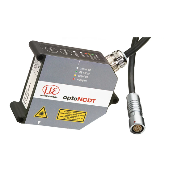
Page 29: Indicator Elements At Sensor
The programmable touch key Select calls up the functions Masters or Teaching. By factory default both keys are only active for the first 5 minutes after power up. After that it will be automatically locked. The touch key Function calls up the settings menu. The key lock can be programmed via internal websites or ASCII commands. optoNCDT 1750 Page 29... -
Page 30: Electrical Connections
The different periphery devices can be connected by the illustrated connection cables to the 14-pin sensor plug, see Fig. 15. The sin- gle converter IF2004/USB, double converter C-Box/2A, 4-times converter IF2004/USB and the PCI interface card IF2008 also supply the operating voltage (24 V DC) of the sensor. optoNCDT 1750 Page 30... - Page 31 IF2004/USB; IF2008, PCI interface card four RS422 C-Box 2A SPS, ILD1750 or the like Functional input: trigger Switch, key, PLC or the like Switching input laser On/Off Fig. 16 Max. sensor channels on the peripheral devices optoNCDT 1750 Page 31...
-
Page 32: Pin Assignment
The sensor cable PC1700 is cable carriers suitable. One end has a molded female cable connector, the other „Triggering“. end has free leads with ferrules. Plug connector: ODU MINI-SNAP , 14-pin, series B, dimension 2, Code 0, IP 68 ; More information on www.odu.de optoNCDT 1750 Page 32... -
Page 33: Supply Voltage
11 ... or similar sources of pulse interference at 30 VDC ILD1750 the same time. MICRO-EPSILON recom- mends using an optional available power supply unit PS2020 for the sensor. black Ground Fig. 18 Connection of supply voltage... -
Page 34: Laser On
There is no external resistor for current limiting required. Connect Pin 9 with Pin 6 for permanent „Laser on“. Reaction Time for Laser-On: Correct measuring data are sent by the sensor approximately 1 ms after the laser was switched on. optoNCDT 1750 Page 34... -
Page 35: Analog Output
GND (Pin 14) black Voltage output U out ILD1750 = 50 Ohm, I = 5 mA, short circuit protection at 11... = 50 Ohm 7 mA 30 VDC > 20 MOhm ≤ 100 nF Fig. 20 Wiring for analog output optoNCDT 1750 Page 35... -
Page 36: Multifunction Input
Use a shielded cable Rx + (Pin 12) grey Tx + (Pin 1) with twisted cores e.g. PC1700-x. Rx -(Pin 11) yellow Tx -(Pin 2) GND (Pin 6) black GND (Pin 9) Fig. 22 Pin assignment IF2001/USB optoNCDT 1750 Page 36... -
Page 37: Digital Output
PNP (High side) appr. GND Push-Pull Push-Pull, negated Fig. 24 Switching characteristic digital output The digital outputs are activated when measuring object is missing, measuring object too close/too far, no valid measurement value or with an off-limit condition. optoNCDT 1750 Page 37... -
Page 38: Connector And Sensor Cable
Unused open cable ends must be insulated to protect against short circuits or malfunction of the sen- sor. MICRO-EPSILON recommends to use the cable carriers suitable standard connection cable PC1700 of the optional accessories, see Chap. The connector and the cable component are marked with red markings which have to be aligned opposite each other before connection. - Page 39 (control cabinet, PC housing) and avoid ground loops. Never lay signal leads next to or together with power cables or pulse-loaded cables (e.g. for drive units and solenoid valves) in a bundle or in cable ducts. Always use separate ducts. Recommended strand cross-section for self-made connection cables: ≥ 0.14 mm² (AWG 25). optoNCDT 1750 Page 39...
-
Page 40: Operation
Operation Getting Ready for Operation Install and assemble the optoNCDT 1750 in accordance with the instructions set out, see Chap. Connect the sensor with the indicator or monitoring unit and the power supply. The laser diode in the sensor can only be activated if at the input Laser on/off Pin 9 is connected with Pin 6, see Chap. -
Page 41: Operation Via Web Interface
The tool searches for connected ILD1750 sensors by means of an internal auxiliary program on available interfaces. You need a web browser (e.g. Mozilla Firefox or Internet Explorer) on a PC/notebook. Choose the desired sensor. Click on the button Open WebPage. optoNCDT 1750 Page 41... -
Page 42: Access Via Web Interface
Fig. 26 First interactive web- site after selection of the web interface The sensor is active and supplies measurement values. The ongoing measurement can be operated by means of function buttons in the area. optoNCDT 1750 Page 42... - Page 43 After programming all the settings are to be stored permanently in a set of parameters. The next time you turn on the sensor they are available again. Therefore use the button Save settings. If the sensor starts with user defined measurement setting (setup), changing the signal quality is not possible. optoNCDT 1750 Page 43...
-
Page 44: Measurement Configuration
Standard Ceramics, metal Multi-Surface Printed circuit boards (PCB), hybrid material Light penetration Plastics (Teflon, POM), materials with large penetration depth of the laser 1) Available for ILD1750-2/10/20/50/2LL/10LL/20LL/50LL sensors optoNCDT 1750 Page 44... -
Page 45: Measurement Presentation Via Web Browser
Stop stops the diagram; data selection and zoom function are still possible. Pause interrupts recor- ding. Save opens the Windows selection dialog for file name and storage location to save the last 10,000 values in a CSV file (separation with semicolon). optoNCDT 1750 Page 45... - Page 46 If you leave the diagram display in a separate tab or window of the browser running, you do not have to restart the description each time. Click the button Start, for starting the display of the measurement results.. optoNCDT 1750 Page 46...
-
Page 47: Video Signal Via Web Browser
0 % (distance small) on the left and 100 % (distance big) on the right. The related measurement value is marked by means of a vertical line (peak marking). Fig. 28 Display of video signals optoNCDT 1750 Page 47... - Page 48 10 Choice of a diagram type: measurement or video signal representation. By displaying the video signal, you can detect effect of the adjustable measurement task (target material), choice of peak and possible interfering signals by means of reflections. optoNCDT 1750 Page 48...
-
Page 49: Programming Via Ascii Commands
Each cycle takes 133.3 µs at a measuring rate of 7.5 kHz. The measured value N is available at the output af- ter four cycles. The delay between acquisition and output is therefore 553 µs. As the processing in the cycles occurs parallel, after another 133.3 µs, the next measured value (N+1) is output. optoNCDT 1750 Page 49... -
Page 50: Menu Structure, Operation Via Membrane Keys
Store and activate function settings Legend navigating through options; select function briefly press key <0.5 sec. making a selection; enter/leave menu; select function press key for approx. 3 sec. press key for approx. 3 sec. optoNCDT 1750 Page 50... - Page 51 LED State flashes red 2.5 kHz Measuring 7.5 kHz 300 Hz 625 Hz 1.25 kHz select select select select 5 kHz rate LED Output flashes yellow select select select select Store and activate settings optoNCDT 1750 Page 51...
-
Page 52: Setting Sensor Parameters
If the programming is not permanently stored on the sensor, the settings will be lost after switching off the sensor. Overview Parameter The following parameters can be set or changed in the optoNCDT 1750, see tab Settings. Inputs Laser power, Synchronization, Multi-function input... -
Page 53: Inputs
Laser on/off and Multi-function. TTL: Low ≤ 0,8 V; High ≥ 2 V HTL: Low ≤ 3 V; High ≥ 8 V Grey shaded fields require a selection. Dark-bordered fields require Value you to specifie a value. optoNCDT 1750 Page 53... -
Page 54: Data Recording
At a maximum measuring rate of 7.5 kHz, the CMOS element is exposed 7500 times per second. The lower the measuring rate, the longer the maximum exposure time. The measuring rate is factory set to 2.5 kHz. Grey shaded fields require a selection. Dark-bordered fields require Value you to specifie a value. optoNCDT 1750 Page 54... -
Page 55: Triggering
7.4.3.1 General The value input and output on the optoNCDT 1750 can be controlled through an external electrical trigger signal or commands. Both analog and digital outputs are affected. The measured value to the trigger point is output delayed, see Chap. 6.4. - Page 56 Software triggering. Data recording is caused by the TRIGGERSW SET command. The sensor outputs the previously set number of measured values or initiates a continuous measured value output after the trigger event. Measurement value output can also be stopped via a command. optoNCDT 1750 Page 56...
-
Page 57: Triggering Data Recording
Therefore, any values measured immediately before the trigger event are included in calculating mean values (averages). Activating the data recording trigger deactivates the data recording trigger. optoNCDT 1750 Page 57... -
Page 58: Masking The Evaluation Range, Roi
Masking limits the evaluating range (ROI - Region of Interest) for the distance calculation in the video signal. This function is used in order to e.g. suppress interfering reflections or ambient light. Masked area Measuring range Fig. 31 Light blue areas limit the evaluation range optoNCDT 1750 Page 58... -
Page 59: Exposure Mode
50 Range [%] 100 fields require a area. selection. If a measurement object contains multiple transparent layers, a correct measurement result is determined only for the first peak. Dark-bordered fields require Value you to specifie a value. optoNCDT 1750 Page 59... -
Page 60: Error Processing
After this period has expired, an error value is output. Grey shaded fields require a selection. Dark-bordered fields require Value you to specifie a value. optoNCDT 1750 Page 60... -
Page 61: Signal Processing
Dark-bordered depth. fields require Value you to specifie The defined type of average value and the averaging number must be stored in the sensor to ensure a value. they are hold after it is switched off. optoNCDT 1750 Page 61... -
Page 62: Moving Average
= M (n+1) Output value Special features: Moving average in the optoNCDT 1750 allows only potentials of 2 for N. Range of values for averaging num- ber N is 1 / 2 / 4 / 8 ... 128. optoNCDT 1750... -
Page 63: Recursive Average
Example: average value from five readings ... 0 1 2 4 5 1 3 Sorted measurement values: 1 2 3 4 5 Median ... 1 2 4 5 1 3 5 Sorted measurement values: 1 3 4 5 5 Median (n+1) optoNCDT 1750 Page 63... -
Page 64: Zeroing And Mastering
An invalid master value, e.g. no peak present, is acknowledged Value you to specifie with the Error E602 Master value is out of range. a value. optoNCDT 1750 Page 64... -
Page 65: Zeroing, Mastering Using The Select Button
1) The Select button has no effect as the key lock is active. 2) When the State LED is red, the master value is not accepted. Flashing frequency of the red State LED is 8 Hz for 2 s. optoNCDT 1750 Page 65... -
Page 66: Zeroing, Mastering Via Hardware Input
The zeroing/mastering function can be applied several times in a row. Maintain a break of 1 s before repeat- ing the zeroing/mastering function. 1) If the master position is outside the measuring range, the master value is not accepted. optoNCDT 1750 Page 66... -
Page 67: Output Trigger
3,000,000. This allows you to adjust slower processes, such as a PLC, to the fast sensor without having to reduce the measuring rate. Grey shaded fields require a selection. Dark-bordered fields require Value you to specifie a value. optoNCDT 1750 Page 67... -
Page 68: Outputs
The hysteresis defines a dead band around the Switching level NPN / PNP / PushPull / selected limit values. PushPull negative Minimum holding period 1 ... 1000 ms Value Hystereses 0 ... 2 x Measu- Value ring range optoNCDT 1750 Page 68... - Page 69 The switching outputs 1 and 2 can be activated regardless of any other channel. While using the web interface, the output is switched off via RS422. Grey shaded fields require a selection. Dark-bordered fields require Value you to specifie a value. optoNCDT 1750 Page 69...
-
Page 70: Digital Output, Rs422
EMR = End of measuring range Bit 6: Distance after EMR (extended) Bit 15: Measurement value is triggered Bit 16, 17: Status LED; - 00 – off 10 – red - 01 – green 11 – yellow optoNCDT 1750 Page 70... - Page 71 There is no peak present 262077 Peak is located in front of the measuring range (MR) 262078 Peak is located after the measuring range (MR) 262080 Measurement value cannot be evaluated 262081 Peak is too wide 262082 Laser is off optoNCDT 1750 Page 71...
-
Page 72: Behavior Of The Digital Output
Target Target Target 16 % 100 % MR 60 % 100 % MB 60 % 100 % MR -16.00 mm 84.00 mm -60.0 mm 40.00 mm -50.0 mm 50.00 mm 87746 153282 58910 124446 65464 131000 optoNCDT 1750 Page 72... - Page 73 [mm] Distance after 98232 mastering 97576 50 % 100 % [mm] 120 SMR‘ 220 EMR‘ Reserve measuring range Fig. 36 Digital values without zeroing or mastering Fig. 37 Digital values ILD1750-100 after mastering with 200 mm optoNCDT 1750 Page 73...
-
Page 74: Analog Output
- too far from the sensor - outside the EMR LED State Error Error the teaching process is aborted. Measuring object Fig. 38 Standard characteristic (black), reversed, within range Switch user-specific characteristic (red) output 1) With current output 3.0 mA. optoNCDT 1750 Page 74... -
Page 75: Output Scaling With The Select Button
When the Select button is pressed longer than 10 s or not within the time frame when resetting the output scaling, the State LED will this display as error. The State LED then flashes for two seconds with 8 Hz. optoNCDT 1750 Page 75... -
Page 76: Output Scaling Via Hardware Input
Fig. 41 Flow chart for output scaling Measuring Pin 10 (white-green) 200 ms t 4 - t 2 = 2 s Switch output 1 5 ... <10 s t 2 t 3 Fig. 42 Flow chart for resetting the output scaling optoNCDT 1750 Page 76... -
Page 77: Calculation Of The Measurement Value At The Current Output
= current [mA] [4; 20] Measuring range [>20; 20.2] EMR reserve [mA] - 4) [mm] [mm] - m [mm]| = Measuring range [mm] {2/10/20/50/100/200} m, n = Teaching range [mm] [0; MR] = Distance [mm] [m; n] optoNCDT 1750 Page 77... -
Page 78: Calculation Of The Measurement Value From The Voltage Output
[0; 5] Measuring range [>5; 5.05] EMR reserve = Voltage [V] [-0.1; <0] SMR reserve [mm] * MR [mm] [0; 10] Measuring range [>10; 10.1] EMR reserve MR = Measuring range [mm] {2/10/20/50/100/200} = Distance [mm] [-0.01MR; 1.01MR] optoNCDT 1750 Page 78... - Page 79 = Voltage [V] [-0.1; <0] SMR reserve [mm] [mm] - m [mm]| [0; 10] Measuring range [>10; 10.1] EMR reserve = Measuring range [mm] {2/10/20/50/100/200} m, n = Teaching range [mm] [0; MR] = Distance [mm] [m; n] optoNCDT 1750 Page 79...
- Page 80 MR = Measuring range [mm] {2/10/20/50/100/200} MP = Master position [mm] [0; MR] for MP £ 0.5MR: [-MP; 0.5MR] m, n = Teaching range [mm] for MP > 0.5MB: [-0.5MR; MR - MP] = Distance [mm] [m; n] optoNCDT 1750 Page 80...
-
Page 81: Behavior Distance Value And Analog Output
Analog output achieves minimum value Analog output achieves maximum value with 66 % of the MR with 10 % of the MR MR = Measuring range, SMR = Start of measuring range, EMR = End of measuring range optoNCDT 1750 Page 81... - Page 82 Analog output achieves minimum value Analog output achieves maximum value with 66% of the MR with 10% of the MR MR = Measuring range, SMR = Start of measuring range, EMR = End of measuring range optoNCDT 1750 Page 82...
- Page 83 10 mm (30 mm) (-15 mm) (30 mm) Out min -0.1 V 16 % 50 % 60 % 100 % Reserve measuring range Fig. 44 Voltage output with zeroing or mastering; U = 0 ... 10 V optoNCDT 1750 Page 83...
-
Page 84: Analog Output Mastering And Teaching
60 % EMR’ 100 % MR Fig. 45 Output characteristic after mastering and scaling with an ILD1750-50 -10.0 mm 10.00 mm 1) U = 0 ... 10 V 4.00 mA 0.00 V 20.00 mA 10.00 V optoNCDT 1750 Page 84... -
Page 85: Switching Outputs
Switching output 2 reacts to a measuring EMR = End of measuring range range violation. The function of the switching out- = Maximum puts is generally independent of the analog output. = Hysteresis value = Minimum SMR = Start of measuring range optoNCDT 1750 Page 85... -
Page 86: Data Output
- send software command Reset to the sensor. 7.6.5 Data Output Measurement data output via individual channels can be activated/deactivated in this menu. Please refer to RS422 and Analog output, see Chap. 7.6.2, see Chap. 7.6.3 for the interface settings. optoNCDT 1750 Page 86... -
Page 87: System Settings
Active The keys do not respond in any user level Grey shaded fields require a selection. Inactive The keys are active in any user level Dark-bordered fields require Value you to specifie a value. optoNCDT 1750 Page 87... -
Page 88: Load And Safe
A. area A. The dialog Measurement set- e.g. Rubber1_21 and The dialog Measurement set- tings opens. click the button Save. tings opens. Click on the button Favorite. Click on the button Load. optoNCDT 1750 Page 88... - Page 89 The dialog Measurement settings opens. Click on the button Search. Click on the button Export. A Windows dialog for file selections opens. Choose the desired file and click on the button Open. Click on the button Import. optoNCDT 1750 Page 89...
-
Page 90: Import, Export
Download. The file name for the adjacent parameter set. example is <...\Downloads\ILD1750_BA- SICSETTINGS_MEASSETTINGS_... In order to avoid that an already existing setup is overwritten unintention- ally during import, an automatic security request is carried out (see adjacent figure). optoNCDT 1750 Page 90... -
Page 91: Access Authorization
Fig. 49 Permissions within the user hierarchy Enter the standard password “000” or a custom password into the Pass- word box, and click Login to confirm. Change to the User level by clicking the Logout button. Fig. 50 Changing to professional level optoNCDT 1750 Page 91... -
Page 92: Reset Sensor
Defines the user level that is enabled when the sensor starts the restarting Professional next time. MICRO-EPSILON recommend to select User level. After the sensor has been configured, you should enable password protection. Please write down the pass- word for later use. -
Page 93: Digital Interfaces Rs422
If data output is overloaded, an error value is transmitted within the distance value. Use the command GETOUTINFO_RS422 to query for data selection and output sequence. optoNCDT 1750 Page 93... -
Page 94: Conversion Of The Binary Data Format
The sensor continues to deliver measurement values to the RS422 output even while communicating with the sensor. For the data transmission with a PC the MICRO-EPSILON IF2008 PCI BUS interface card is suitable. This can be connected to the sensor via the PC1700-x/IF2008 interface cable, which is also available as an option. -
Page 95: Cleaning
Therefore an optics anti-static brush is suitable or bleeding the screen with dehumidified, clean and oil-free compressed air. Wet Cleaning For cleaning the protective screen use a clean, soft, lint-free cloth or lens cleaning paper with pure alcohol (isopropyl). Never use standard glass cleaner or other cleaning agents. optoNCDT 1750 Page 95... -
Page 96: Protective Housing
The rotatable plug-nipple glands type LCKN-1/8-PK-6 (FESTO) for the compressed-air tubes with a inner diameter of 6 mm, the air plate (SGHF) and the sensor fastening accessories are included in the delivery of the protective housing. optoNCDT 1750 Page 96... - Page 97 Air inlet (Air supply can be pivoted, for flexible tube with 6 mm inner diameter) Laser spot 47.9 (1.89) 125 (4.92) 140 ((5.51) (1.10) 168 (6.61) Fig. 51 Protective housing for measuring ranges 2/10/20/50/100/200 mm optoNCDT 1750 Page 97...
- Page 98 6 mm inner diameter) 60.0 42.0 28.0 (1.65) (1.1) Mounting holes ø4.5 (dia. .18) 165 (6.50) 32.5 71 (2.80) (1.28) 42.5 180 (7.09) (1.67) Laser spot Laser spot Fig. 52 Protective housing for measuring range 40 and 200 mm optoNCDT 1750 Page 98...
-
Page 99: Software Support With Medaqlib
- works independent of the used interface type, - features by identical functions for the communication (commands), - provides a consistent transmission format for all MICRO-EPSILON sensors. For C/C++ programmers MEDAQLib contains an additional header file and a library file. You will find the lat- est driver / program routine at: www.micro-epsilon.com/download... -
Page 100: Liability For Material Defects
The liability for material defects is 12 months from delivery. Within this period, defective parts, except for wearing parts, will be repaired or replaced free of charge, if the device is returned to MICRO-EPSILON with shipping costs prepaid. Any damage that is caused by improper handling, the use of force or by repairs or modifications by third parties is not covered by the liability for material defects. -
Page 101: Appendix
Würth 691361100006 IF2004/USB 4 channel converter RS422 to USB useable for cable PC1700-x/IF2008 (IF2008-Y), inclusive driver, connections: 2× Sub-D, 1× terminal block PS2020 Power supply for mounting on DIN rail, input 230 VAC, output 24 VDC/2.5 A optoNCDT 1750 Seite 101... - Page 102 Length x = 3, 5, 6, 10, 12, 20, 25 or 30 m 14-pin molded connector resp. open ends PC1700-x/IF2008 Interface and supply cable Length x = 3, 6, 8 or 20 m 14-pin. molded connector resp. 15-pin Sub-D- connector optoNCDT 1750 Seite 102...
-
Page 103: Factory Setting
Key Select is pressed during start sequence (t ... t Key Select is released while the LED State is flashing red Dt = t ; Dt (key press period) must be at least 10 sec., max. 15 sec. optoNCDT 1750 Seite 103... -
Page 104: A 3 Ascii Communication With Sensor
[]-brackets are to input compulsory, that is, it must not be omitted a parameter. Alternative inputs of parameter values are displayed separately by „|“, for example the values „a“, „b“ or „c“ can be set for “a|b|c“. Parameter values in <> brackets are selectable from a value range. optoNCDT 1750 Seite 104... - Page 105 These are analogous to the error messages. In case of warnings the command is executed. The replies to the commands GETINFO and PRINT are useful for support requests to the sensor, because they contain sensor settings. optoNCDT 1750 Seite 105...
-
Page 106: A 3.2 Overview Commands
Select Trigger Source Chap. A 3.2.3.4 TRIGGERAT Effect of the Trigger Input Chap. A 3.2.3.5 MFILEVEL Select level for switching input Chap. A 3.2.3.6 TRIGGERCOUNT Number of measurement values displayed Chap. A 3.2.3.7 TRIGGERSW Software - Trigger Pulse optoNCDT 1750 Seite 106... - Page 107 Voltage or current output Chap. A 3.2.6.2 ANALOGSCALEMODE Scaling analog output Chap. A 3.2.6.3 ANALOGSCALERANGE Scaling limits analog output Chap. A 3.2.6.4 ANALOGSCALESOURCE Port for teach function Key function Chap. A 3.2.7.1 KEYLOCK Set key lock optoNCDT 1750 Seite 107...
- Page 108 Selection measurement value output for reduction Chap. A 3.2.9.3 OUTREDUCECOUNT Reduction of measurement value output Chap. A 3.2.9.4 OUTHOLD Setting of error processing Chap. A 3.2.9.5 GETOUTINFO_RS422 List intended data for RS422 Chap. A 3.2.9.6 OUT_RS422 Measurement data output with RS422 optoNCDT 1750 Seite 108...
-
Page 109: A 3.2.1 General Commands
Cursor, the sensor waits for an entry E<dd> <Msg> Error message, execution refused W<dd> <Msg> Warning <ddd> Three digits <Msg> Message Format Group Optional parameters <> Placeholder Alternative If spaces are used in parameters, the parameters must be placed in quotation marks. optoNCDT 1750 Seite 109... -
Page 110: A 3.2.1.2 Getinfo, Sensor Information
// Serial number Option: //Option number of sensor Article: 4120176 // Article number of sensor Cable head: Pigtail Measuring range: 10.00mm // Measuring range of the sensor Version: 003.018.001 //Software version Hardware-rev: Boot version: 002.010 -> optoNCDT 1750 Seite 110... -
Page 111: A 3.2.1.3 Language, Website
ECHO, Switching the Command Reply, ASCII Interface ECHO ON|OFF Setting the command reply with an ASCII command: - ON: command reply on, for example ok (or error message) -> - OFF: command reply off, e.g. -> optoNCDT 1750 Seite 111... -
Page 112: A 3.2.1.7 Print, Sensor Settings
AVERAGE MEDIAN 9 ERROROUTHOLD 0 TRIGGERSOURCE NONE ERRORLIMITCOMPARETO1 LOWER TRIGGERMODE EDGE ERRORLIMITCOMPARETO2 LOWER TRIGGERLEVEL HIGH ERRORLIMITVALUES1 0.0000 10.0000 TRIGGERAT INPUT ERRORLIMITVALUES2 0.0000 10.0000 TRIGGERCOUNT 1 ERRORHYSTERESIS 0.0000 MASTERSIGNAL SHUTTERMODE MEAS MASTERSIGNAL DIST1 0.000 SHUTTER 100.0 MASTERSOURCE NONE -> optoNCDT 1750 Seite 112... -
Page 113: A 3.2.1.8 Sync
2 sensor on transparent material - SLAVE: Sensor is slave and expects synchronization pulses from another optoNCDT 1750. - SLAVE_ALT: Sensor is slave and expects synchronization pulses from a master sensor. Both sensors mea- sure alternately, e.g. -
Page 114: A 3.2.1.9 Termination
Sets the standard user, who is logged in after system start. Standard user does not change with LOGOUT, i.e. login as standard user is done automatically after the command RESET or power supply of sensor is switched on. optoNCDT 1750 Seite 114... -
Page 115: A 3.2.2.5 Passwd, Change Password
TRIGGERSOURCE NONE | MFI | SYNCIO | SOFTWARE - NONE: Triggering is deactivated - MFI: Use multi-function input for triggering. - SYNCIO: Use synchronization ports for triggering - SOFTWARE: Triggering is controlled by the TRIGGERSW command optoNCDT 1750 Seite 115... -
Page 116: A 3.2.3.4 Triggerat, Effect Of The Trigger Input
- SET: Generates one single trigger pulse when edge triggering (EDGE) is active. Continuously generates trigger pulses with level triggering (PULSE) - CLR: Stops trigger pulses with level triggering (PULSE). With edge triggering, an ongoing task is aborted. Abortion is also possible when selecting the trigger sources MFI and SyncIO. optoNCDT 1750 Seite 116... -
Page 117: A 3.2.4 Interfaces
Defines the monitoring function for the switching outputs. - LOWER: Monitors if the measurement value falls short of the limit value - UPPER: Monitors if the measurement value exceeds the limit value - BOTH: Monitors excess/shortfall of limit values. optoNCDT 1750 Seite 117... -
Page 118: Errorlimitvalues1/2
When importing all measurement settings or device settings (= BASICSETTINGS) FORCE must always be stated. - APPLY : Activates the settings after importing / reading the Initial Settings. - ImportData: Data in JSON format optoNCDT 1750 Seite 118... -
Page 119: A 3.2.5.2 Export
ƒ DELETE <Name>: Deletes a measurement setting. ƒ INITIAL AUTO: Loads the last saved setting when starting the sensor ƒ INITIAL <Name>: Loads the setting <Name> when starting the sensor. Presets cannot be indicated. ƒ LIST: Lists all saved measurement settings. optoNCDT 1750 Seite 119... -
Page 120: A 3.2.5.4 Basicsettings, Load / Save Device Settings
ƒ Minimum value: measurement value in mm which is matched to the lower analog value, ƒ Maximum value: measurement value in mm which is matched to the upper analog value. The minimum value (in mm) can be higher than the maximum value (in mm), see Chap. 7.6.3. optoNCDT 1750 Seite 120... -
Page 121: A 3.2.6.3 Analogscalerange, Scaling Limits With Two-Point Scaling
A 3.2.6.4 ANALOGSCALESOURCE ANALOGSCALESOURCE NONE | MFI | KEY_SELECT Determination of the port for teaching. - NONE: No port selected. - MFI: Switching input triggers teaching function. - KEY_SELECT: The Select key triggers the teaching function. optoNCDT 1750 Seite 121... -
Page 122: A 3.2.7 Key Function
- DISTW: output of peak with the largest area - DIST1: output of first peak - DISTL: output of last peak A 3.2.8.3 MEASRATE, Measuring rate MEASRATE <frequency> Specifies the measuring rate in kHz, range 0.3 … 7.5 kHz. optoNCDT 1750 Seite 122... -
Page 123: A 3.2.8.4 Shutter, Exposure Time
- MOVING: Moving average (averaging depth <AD> of 2, 4, 8, 16, 32, 64, and 128 possible). - RECURSIVE: Recursive average (averaging depth <AD> of 2 to 32768 possible) - MEDIAN: Median (averaging depth <AD> of 3, 5, 7 and 9 possible) optoNCDT 1750 Seite 123... -
Page 124: A 3.2.8.9 Master
Choice of port for mastering. - NONE: No port (hardware) selected, mastering is possible via command. - MFI: Use switching input in order to trigger mastering. - KEY_SELECT: Use Select key in order to trigger mastering. optoNCDT 1750 Seite 124... -
Page 125: A 3.2.9 Data Output
- NONE: No holding of the last measured value, output of error value. - INFINITE: Infinite holding of the last measurement value. - <n>: Holding the last measured value over a number of measuring cycles n; then an error value is output. n = (1 ... 1024). optoNCDT 1750 Seite 125... -
Page 126: A 3.2.9.5 Getoutinfo_Rs422, Query Selected Data
- TIMESTAMP_LO: Time stamp (16 Bit lower word) - TIMESTAMP_HI: Time stamp (16 Bit upper word) - INTENSITY: intensity - STATE: Status word - UNLIN: Non-calibrated distance value (raw value) - VIDEO: video signal (raw value) - MEASRATE: measuring rate (frequency) optoNCDT 1750 Seite 126... -
Page 127: Example Command Sequence During Selection Of Measurement Value
OUTREDUCECOUNT OUTHOLD Output behavior in the event of measuring errors OUTADD_RS422 Selection of the additional values to be output for RS422 interface BAUDRATE Baud rate setting RS422 interface optoNCDT 1750 Seite 127... -
Page 128: A 3.4 Error Messages
E322 Error during data transmission of the Only with update: Error with transmission of update data. update E323 Timeout during the update Only with update: Timeout with transmission of update data. E331 Validation of import file failed Import file is invalid optoNCDT 1750 Seite 128... - Page 129 W320 The measuring output has been The measurement value output has been adapted auto- adapted automatically. matically. W570 The input has been adapted automati- The input has been adapted automatically to a limited cally to a limited range. range. optoNCDT 1750 Seite 129...
-
Page 130: A 4 Control Menu
Level Multi-function input TTL / HTL Defines the input level of both switching inputs La- ser on/off and Multi-function. TTL: Low ≤ 0.8 V; High ≥ 2V HTL: Low ≤ 3 V; High ≥ 8V optoNCDT 1750 Seite 130... -
Page 131: Data Recording
Setting the evaluation range for the „Region of interest“, i.e. only this range is used for logging the measuring values. The Start of range value has to be smaller than the End of range value. End of range 1 ... 100 % Value optoNCDT 1750 Seite 131... - Page 132 5.2 / 10.2 V instead of measurement value. The RS422 interface outputs an error value. Hold last value infinite Analog output and RS422 interface stop at the last valid value. Hold last value 1 ... 1024 Value optoNCDT 1750 Seite 132...
-
Page 133: A 4.2.3 Signal Processing
Indicates the sensor which data is to be excluded from output, thus the data amount to be transmitted is reduced. Reduction relates RS422 / Analog Interfaces to be used for undersampling are to be selected via the check- box. optoNCDT 1750 Seite 133... -
Page 134: Outputs
The hysteresis defines a dead band around the Switching level NPN / PNP / PushPull / selected limit values. PushPull negative Minimum holding period 1 ... 1000 ms Value Hystereses 0 ... 2 x Measu- Value ring range optoNCDT 1750 Seite 134... - Page 135 RS422 and analog output cannot be operated simultaneously. The switching outputs 1 and 2 can be activated regardless of any other channel. While using the web interface, the output is switched off via RS422. optoNCDT 1750 Seite 135...
-
Page 136: System Settings
Safe Saves changed device settings. Search You load the device settings from a PC or the like to the ILD1750 with both buttons. Import Export Saves the device settings on a connected PC or the like. optoNCDT 1750 Seite 136... - Page 137 Read only permission Logout / Login Button starts change of access permission. Sets the user level the sensor starts with after re- User level when boot. In this case MICRO-EPSILON recommends the Professional / User restarting selection user. password Value Case-sensitive rules are observed for all passwords.
- Page 138 Selection required or checkbox After the programming all settings must be permanently stored under a parameter set so that they are available again when the sensor is switched on the next time. Value Specification of a value required optoNCDT 1750 Seite 138...
- Page 140 MICRO-EPSILON MESSTECHNIK GmbH & Co. KG X9751376-A031098MSC Königbacher Str. 15 · 94496 Ortenburg / Deutschland MICRO-EPSILON MESSTECHNIK Tel. +49 (0) 8542 / 168-0 · Fax +49 (0) 8542 / 168-90 *X9751376-A03* info@micro-epsilon.de · www.micro-epsilon.de...
Need help?
Do you have a question about the optoNCDT 1750 and is the answer not in the manual?
Questions and answers