Table of Contents
Advertisement
Quick Links
Advertisement
Table of Contents

Related Manuals for MICRO-EPSILON optoNCDT 2300


Summary of Contents for MICRO-EPSILON optoNCDT 2300
- Page 1 Instruction Manual optoNCDT 2300 ILD2300-2 ILD2300-100 ILD2300-2LL ILD2300-2BL ILD2300-2DR/R ILD 2310-10 ILD2300-5 ILD2300-200 ILD2300-10LL ILD2300-5BL ILD2300-2DR/BL ILD 2310-20 ILD2300-10 ILD2300-300 ILD2300-20LL ILD2300-10BL ILD 2310-40 ILD2310-50BL ILD 2310-50 ILD2300-20 ILD2300-50LL ILD2300-50...
- Page 2 MESSTECHNIK GmbH & Co. KG Königbacher Strasse 15 94496 Ortenburg / Germany Tel. +49 (0) 8542 / 168-0 Fax +49 (0) 8542 / 168-90 e-mail info@micro-epsilon.de www.micro-epsilon.com EtherCAT® is registered trademark and patented technology, licensed by Beckhoff Automation GmbH, Germany.
-
Page 3: Table Of Contents
Housing 2DR ..............................36 Electrical Connections ........................... 38 5.6.1 Connection Possibilities ....................... 38 5.6.2 Supply Voltage ..........................40 5.6.3 Laser on ............................40 5.6.4 Input and Outputs......................... 41 5.6.5 Ethernet ............................42 5.6.6 EtherCAT............................43 5.6.7 Connector and Sensor Cable....................... 44 optoNCDT 2300... - Page 4 Triggering ............................68 7.6.1.1 Signal Processing without Trigger ................71 7.6.1.2 Signal Processing - Value Output Trigger ..............72 7.6.1.3 Signal Processing - Trigger for Acquiring Values ............73 7.6.1.4 Signal Processing - Trigger for Outputting all Values ..........74 optoNCDT 2300...
- Page 5 Change Ethernet to EtherCAT ........................93 Value Output ........................... 94 RS422................................94 9.1.1 Possible Output Values and Output Sequence (RS422) ............. 96 9.1.2 Error Codes ..........................97 Ethernet ................................98 EtherCAT ................................ 98 Analog Output ..............................98 Error Handling ............................... 99 optoNCDT 2300...
- Page 6 Decommissioning, Disposal ....................110 Service, Repair ........................111 Appendix Optional Accessories ........................... 112 Factory Setting ............................. 116 A 2.1 Parameters ..............................116 A 2.2 Set Default Settings ............................. 117 PC2300-0.5/Y ............................... 118 PC2300-x/OE ............................... 119 IF2004/USB ..............................120 optoNCDT 2300...
- Page 7 A 6.3.4.4 Change between Ethernet / EtherCAT ..............135 A 6.3.4.5 Units Web-Interface ....................135 A 6.3.5 Load / Save Settings ........................135 A 6.3.5.1 Save Parameter ......................135 A 6.3.5.2 Load Parameter ......................135 A 6.3.5.3 Default Settings ......................135 optoNCDT 2300...
- Page 8 A 6.5.2.4 Data Selection Statistic Values .................. 143 A 6.5.2.5 Data Selection Optional Values ................143 A 6.5.2.6 Set Video Output ....................... 143 A 6.6 Example Command Sequence During Measurement Selection ..............144 A 6.7 Error Messages ............................145 optoNCDT 2300...
- Page 9 A 7.3.3.8 Object 2154h: Measuring program ................163 A 7.3.3.9 Object 2161h: Peak selection at distance measuring ..........163 A 7.3.3.10 Object 2181h: Averaging, error processing, statistics and spike correction ... 164 A 7.3.3.11 Object 21B0h: Digital interfaces, selection of transmitted data (measurements) ..166 optoNCDT 2300...
- Page 10 A 7.9 Meaning of EtherCAT-STATUS-LED ......................184 A 7.10 EtherCAT Configuration with the Beckhoff TwinCAT©-Manager ..............185 A 7.11 Finish EtherCAT ............................191 A 7.12 Troubleshooting ............................192 Control Menu ............................... 196 Measuring Value Format Ethernet ....................... 204 optoNCDT 2300...
-
Page 11: Safety
Avoid shock and vibration to the sensor. > Damage to or destruction of the sensor Mount the sensor only to the existing holes on a flat surface. Clamps of any kind are not permitted > Damage to or destruction of the sensor optoNCDT 2300 Page 11... -
Page 12: Notes On Ce Marking
The EU Declaration of Conformity and the technical documentation are available to the responsible authorities according to the EU Directives 7. Intended Use - The optoNCDT 2300 system is designed for use in industrial and laboratory areas. - It is used ƒ for measuring displacement, distance, position and elongation ƒ... -
Page 13: Proper Environment
- Storage temperature: -20 °C ... 70 °C (-4 up to +158 °F) - Humidity: 5 - 95 % (no condensation) - Ambient pressure: Atmospheric pressure The protection class is limited to water, no penetrating liquids or similar! optoNCDT 2300 Page 13... -
Page 14: Laser Class
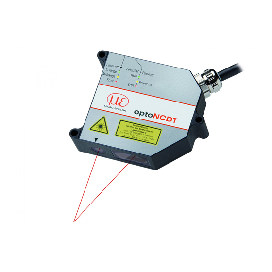
Laser Class The optoNCDT 2300 sensors operate with a semiconductor laser with a wavelength of 670 nm (visible/red ILD2300-x) resp. 405 nm (visible/blue ILD2300-xBL). The sensors fall within Laser Class 2 (II). The laser is operated on a pulsed mode, the average power is ≤ 1 mW in each case, the peak power can be up to 1.2 mW. The pulse frequency depends on the adjusted measuring rate /1.5 ... ... - Page 15 EXCEPT FOR CONFORMANCE WITH IEC 60825-1 ED. 3., AS DESCRIBED IN LASER NOTICE NO. 56, DATED MAY 8, 2019 Laser spot Fig. 1 True reproduction of the sensor with its actual location of the warning labels, ILD2300 optoNCDT 2300 Page 15...
- Page 16 Fig. 2 True reproduction of the sensor with its actual location of the warning labels, ILD2300-x BL If both warning labels are covered over when the unit is installed the user must ensure that supplementary labels are applied. optoNCDT 2300 Page 16...
-
Page 17: Functional Principle, Technical Data
Functional Principle, Technical Data Functional Principle, Technical Data Short Description Sensor Distance Thickness The optoNCDT 2300 operates according to the principle of optical triangulation, i.e. a visible, modulated point of light is projected onto the target surface. With diffuse ar- ILD2300-2 • •... -
Page 18: Real Time Control (A-Rtsc)
Dark or shining objects to be measured may require a longer exposure time. However, the sensor is not capable of providing expo- sure which is any longer than permitted by the measurement frequency. For a longer exposure time, therefore, the measurement frequency of the sensor has to be reduced either manually or by command, see Chap. 7.4.2 optoNCDT 2300 Page 18... -
Page 19: Technical Data
ILD 2310-40 ILD 2300-50 ILD 2310-50 ILD 2300-100 ILD 2300-200 ILD 2300-300 100 mm 200 mm 300 mm 400 mm 500 mm 600 mm Fig. 4 Measuring ranges for displacement measurement in direct and diffuse reflection optoNCDT 2300 Page 19... - Page 20 FSO = Full Scale Output, SMR = Start of measuring range, MMR = Mid of measuring range, EMR = End of measuring range; The specified data ap- ply to white, diffuse reflecting surfaces (Micro-Epsilon reference ceramic for ILD sensors) 1) Second value is valid for a measuring rate of 49.14 kHz 3) Measuring rate of 20 kHz 2) Measuring rate of 49.14 kHz with reduced measuring range...
- Page 21 FSO = Full Scale Output, SMR = Start of measuring range, MMR = Mid of measuring range, EMR = End of measuring range; The specified data ap- ply to white, diffuse reflecting surfaces (Micro-Epsilon reference ceramic for ILD sensors) 1) Second value is valid for a measuring rate of 49.14 kHz 3) Measuring rate of 20 kHz 2) Measuring rate of 49.14 kHz with reduced measuring range...
- Page 22 FSO = Full Scale Output, SMR = Start of measuring range, MMR = Mid of measuring range, EMR = End of measuring range; The specified data ap- ply to white, diffuse reflecting surfaces (Micro-Epsilon reference ceramic for ILD sensors) 1) Second value is valid for a measuring rate of 49.14 kHz 3) Measuring rate of 10 kHz, without averaging 2) Measuring rate of 49.14 kHz with reduced measuring range...
- Page 23 FSO = Full Scale Output, SMR = Start of measuring range, MMR = Mid of measuring range, EMR = End of measuring range; The specified data ap- ply to white, diffuse reflecting surfaces (Micro-Epsilon reference ceramic for ILD sensors) 1) Second value is valid for a measuring rate of 49.14 kHz 3) Measuring rate of 20 kHz, without averaging 2) Measuring rate of 49.14 kHz with reduced measuring range...
- Page 24 FSO = Full Scale Output, SMR = Start of measuring range, MMR = Mid of measuring range, EMR = End of measuring range; The specified data ap- ply to white, diffuse reflecting surfaces (Micro-Epsilon reference ceramic for ILD sensors) 1) Second value is valid for a measuring rate of 49.14 kHz 4) Based on digital output in midrange 2) Measuring rate of 49.14 kHz with reduced measuring range...
-
Page 25: Indicator Elements At Sensor
Laser beam is switched off green In range Sensor in operation State yellow Midrange Target is in midrange Error Target out of range, to low reflection 1) LED display for measuring rates < 49.140 kHz only. optoNCDT 2300 Page 25... -
Page 26: Delivery
- 1 Connection cable PC2300-0,5/Y with 15-pol. SUB-D-plug, RS422/power supply cable (0.5 m long) and Ethernet cable with cable jack RJ45 (0.5 m long). See Appendix for further cables, see Chap. Storage Storage temperature: -20 up to +70 °C (-4 °F up to +158 °F) Humidity: 5 - 95 % (no condensation) optoNCDT 2300 Page 26... -
Page 27: Installation
To align the sensor, please comply with the “Instructions for Operation“, see Chap. 10.3, especially. If the sensors are to be used in soiled environments or in higher ambient temperatures than normal, MICRO-EPSILON recommends the use of protective housings, see Chap. 10.5. -
Page 28: Housing S
The tightening torques specified in the table are approximate and may vary depending on the application. The bearing surfaces surrounding the through-holes (mounting-holes) are slightly raised. Mount the sensor only to the existing through-holes on a flat surface. Clamps of any kind are not permitted. Housing sizes, see Chap. 3.4. optoNCDT 2300 Page 28... - Page 29 MR = Measuring range SMR = Start of measuring range Dimensions in mm (inches) Limits for free space Keep this area free from other light sources and/or their reflections Fig. 8 Dimensional drawing, free space for diffuse reflection optoNCDT 2300 Page 29...
- Page 30 - The Status LED lights up yellow. - Fasten the sensor using three M4 screws. Remove the mounting aid between the sen- sor and the measuring object. Fig. 9 Dimensional drawing, free space for diffuse reflection optoNCDT 2300 Page 30...
-
Page 31: Housing M
The tightening torques specified in the table are approximate and may vary depending on the application. The bearing surfaces surrounding the through-holes (mounting-holes) are slightly raised. Mount the sensor only to the existing through-holes on a flat surface. Clamps of any kind are not permitted. Housing sizes, see Chap. 3.4. optoNCDT 2300 Page 31... - Page 32 SMR = Start of measuring range MMR = Midrange EMR = End of measuring range Dimensions in mm (inches) Fig. 11 Dimensional drawing and free space for the measuring range 200/300 mm End of measuring range optoNCDT 2300 Page 32...
- Page 33 Fig. 12 Dimensional drawing ILD2310, measuring ranges 10/20/40 mm 10 (.39) 20 (.79) 40 (1.57) 95 (3.74) 90 (3.54) 175 (6.89) 100 (3.93) 100 (3.94) 195 (7.67) 105 (4.13) 110 (4.33) 215 (8.46) Dimensions in mm (inches) optoNCDT 2300 Page 33...
-
Page 34: Housing L
The tightening torques specified in the table are approximate and may vary depending on the application. The bearing surfaces surrounding the through-holes (mounting-holes) are slightly raised. Mount the sensor only to the existing through-holes on a flat surface. Clamps of any kind are not permitted. Housing sizes, see Chap. 3.4. optoNCDT 2300 Page 34... - Page 35 M5 or M6 screws from the accessories. (.20) (.94) (3.74) 29.5 132.3 (1.89) (5.21) (1.16) (.55) MR = Measuring range SMR = Start of measuring range Dimensions in mm (inches) Fig. 14 Dimensional drawing and free space for the sensor ILD 2310-50 optoNCDT 2300 Page 35...
-
Page 36: Housing 2Dr
The tightening torques specified in the table are approximate and may vary depending on the application. The bearing surfaces surrounding the through-holes (mounting-holes) are slightly raised. Mount the sensor only to the existing through-holes on a flat surface. Clamps of any kind are not permitted. Housing sizes, see Chap. 3.4. optoNCDT 2300 Page 36... - Page 37 - The Status LED lights up yellow. - Fasten the sensor using three M3 or M4 screws. 40.5 (1.59) 45.5 (1.79) (.14) 86 (3.39) MR = Measuring range 93 (3.66) Dimensions in mm (inches) Fig. 16 Dimensional drawing, ILD2300-2DR/R, ILD2300-2DR/BL optoNCDT 2300 Page 37...
-
Page 38: Electrical Connections
Cable/power supply Interface PC2300-x/OE PC2300-x/CSP IF2030/PNET PC2300-x/OE Extension clamp RS422 IF2001/USB IF2004/USB PS 2020 PC2300-x/IF2008 or PC2300-x/OE PC2300-x/IF2008 and IF2008-Y-Adap- terkabel IF2008/PCIE PC2300-x/C-Box/RJ45 Sensor supply is Ethernet done by peripheral. C-Box/2A Fig. 17 Connection examples on ILD2300 optoNCDT 2300 Page 38... - Page 39 IF2008/PCIE, PCI interface card four Ethernet (network, PC) Ethernet / EtherCAT EtherCAT (master) PLC, ILD2300 or the like Synchronization Switch, button, PLC or the like Switching input laser On/Off Fig. 18 Max. sensor channels on the peripheral devices optoNCDT 2300 Page 39...
-
Page 40: Supply Voltage
PC2300-x/Y Supply drive units or similar sources of pulse interference at the same time. 11 ... Color 30 VDC MICRO-EPSILON recommends using an optional available power supply ILD 2300 unit PS2020 for the sensor. white brown Ground Fig. 19 Connection of supply voltage 5.6.3... -
Page 41: Input And Outputs
1) You will find more cables in appendix. 2) In trigger operation, see Chap. 7.6.1, the input is used for triggering. Plug connector: ODU MINI-SNAP , 14-pol., series B, dimension 2, code F, IP 68. optoNCDT 2300 Page 41... -
Page 42: Ethernet
LASER RADIATION Do not stare into beam Class 2 Laser Product IEC 60825-1: 20xx-xx ≤ 1mW; P ≤ 1.2mW; t=0.5...542 s μ F=1.5...50kHz; =670nm PS2020 230 VAC Fig. 22 Measurement setup with Ethernet connection optoNCDT 2300 Page 42... -
Page 43: Ethercat
Alternatively, a connection via the RS422 extension terminal and the cable PC2300-x/CSP is possible. Both are available as optional accessories. When a sensor ILD2300 is operated together with an Ethernet terminal, so the sensor ILD2300 is also setting to the EtherCAT connection, see Chap. 8.5. optoNCDT 2300 Page 43... -
Page 44: Connector And Sensor Cable
The sensor comes with a permanently mounted connection cable of 0.25 m in length. A 3 m, 6 m or 9 m sensor cable has to be at- tached to the connection cable. MICRO-EPSILON recommends the use of the standard sensor cable in the appendix, see Chap. 1, with a chain-type cable capabil- ity. -
Page 45: Operation
Operation Getting Ready for Operation Install and assemble the optoNCDT 2300 in accordance with the instructions set out, see Chap. Connect the sensor with the indicator or monitoring unit and the power supply. The laser diode in the sensor can only be activated if at the input „Laser on/off“ Pin 1 is connected to 3 and Pin 2 to 4, see Chap. - Page 46 PC uses, for example, the following IP ad- Start a web browser on your PC. Type dress: 169.254.168.1. „ILD2300_Serial number“ in the address bar of your web browser. You will find the latest program version of SensorTool at: www.micro-epsilon.com/service/download/ optoNCDT 2300 Page 46...
-
Page 47: Access Via Ethernet
Fig. 24 First interactive website after selection of the IP address. The look of the website may change depending on the features. Each page contains descriptions of the parameters and so tips for filling out the web site. optoNCDT 2300 Page 47... -
Page 48: Measurement Presentation Via Web Browser
Click the button Start, for starting the display of the measurement results. The demo can only be started, if a possible saving of measured values is completed via Ethernet, because only one of two features can be active via Ethernet. optoNCDT 2300 Page 48... - Page 49 Operation Fig. 26 Display of measurement results optoNCDT 2300 Page 49...
-
Page 50: Video Signal Via Web Browser
- independent of the video averaging settings in the settings menu, - preprocessed through the first signal processing stage. There is no linear relationship between the position of the peaks in the video signal and the output measurement value. Fig. 27 Display of video signals optoNCDT 2300 Page 50... -
Page 51: Programming Via Ascii Commands
Averaging the measured values has no effect on the time behavior. Remember, however, that the sensor needs time for the averaging, until measured values are present according to the set averaging number N. Depending on the nature of the averaging value and the number of averaged values, there are different settling times. optoNCDT 2300 Page 51... - Page 52 Statistics calculation for Statistics calculation for displacement thickness Displacement measurement on Displacement measurement Thickness measurement on direct diffuse reflecting targets on direct reflecting targets reflecting transparent targets Fig. 28 Adjustment possibilities of the optoNCDT 2300 optoNCDT 2300 Page 52...
-
Page 53: Control Menu, Set Sensor Parameter
If you do not save the programming permanently in the sensor, you lost the settings after turning off the sensor. Overview Parameter menu Settings. The following parameters can be set or change in the optoNCDT 2300, see Fig. 25 Login... - Page 54 Specifies the user level, with which the sensor starts after the re-starting. For this purpose, switching on Expert MICRO-EPSILON recommends the selection user. 1) Only if there is no measurement output via a different interface. Otherwise you must be logged in expert mode. Value Grey shaded fields require a selection.
-
Page 55: Default Settings
Direct reflection 7.4.2 Measuring Rate Setting for the measuring rate in the optoNCDT 2300 and so the data rate. Measuring rate 1.5 / 2.5 / 5 / 10 / 20 / 30 / Dark and shining objects may require a slower measuring rate. The control do not 49.140 kHz... -
Page 56: Baud Rate For Rs422
9.1.1 The factor 33 means that per value transmitted 3 bytes are transmitted, with real 11 bit are used on he serial line. Fig. 31 Equation 1, dimensioning of the baud rate without trigger, no synchronization optoNCDT 2300 Page 56... - Page 57 The factor 33 means that per value transmitted 3 bytes are transmitted, with real 11 bit are used on he serial line. Fig. 32 Equation 1, dimensioning of the baud rate with synchronization In alternating synchronization the measuring rate is halved and thus a lower baud rate can also be used. optoNCDT 2300 Page 57...
- Page 58 ODR Output data rate Number of measuring values per trigger edge Trigger pulse duration Trigger pulse pause The factor 33 means that per value transmitted 3 bytes are transmitted, with real 11 bit are used on he serial line. optoNCDT 2300 Page 58...
-
Page 59: Averaging, Error Processing, Spike Correction And Statistics
2 / 4 / 8 / 16 ... 16384 Beyond a certain number of measurement values the sta- tistical values minimum, maximum and peak-to-peak are determined and output. Value Grey shaded fields require a selection. Dark-bordered fields require you to specify a value. optoNCDT 2300 Page 59... -
Page 60: Measurement Averaging
Averaging does not affect the measuring rate or data rates in digital measurement value output. The averaging numbers can also be used if programmed via the digital interfaces. The sensor optoNCDT 2300 is supplied ex factory with the default setting „Median 9“, that is, averaging with Median and 9 measurements. - Page 61 Output value Characteristics: When moving averaging in the optoNCDT 2300 only powers of 2 for the averaging number N are allowed. Range of values for number of average N is 1 / 2 / 4 / 8 ... 128. Recursive Average...
-
Page 62: Spike Correction
- x Evaluation length. Number of previous measured values to be assessed (max. 10). - y Max. tolerance range (mm); the spike (outlier) correction comes into play when the value is not met or is exceeded - z Number of corrected value (max. 100) optoNCDT 2300 Page 62... - Page 63 Example: x = 3 / y = 0.05 / z = 1 10,00 9,95 9,90 9.89 9.88 9.88 9.86 9,85 9.85 9.85 9.83 9,80 9.77 9,75 9.75 Evaluation Number of Max. Average 9,70 length corrected tolerance value value range Fig. 34 Correction of measuring values optoNCDT 2300 Page 63...
-
Page 64: Statistical Values
Control Menu, Set Sensor Parameter 7.4.4.3 Statistical values The optoNCDT 2300 can deduce the following statistical values from the result of measuring or the calculating: Maximum Minimum Maximum Minimum Peak-to-peak Peak-to-peak value PEAK2PEAK (Range) Evaluation cycle Time Fig. 35 Statistical values and evaluation cycle The statistical values are calculated from the measurement values within the evaluation cycle. -
Page 65: Setting Zero And Masters
Fig. 36 Characteristic for mastering “Setting masters“ or “Setting zero“ requires that a target is within the measurement range “Setting masters“ or “Setting zero“. “Setting masters“ and “Setting zero“ has an influence on the digital outputs. optoNCDT 2300 Page 65... -
Page 66: Material Data Base
Is the respective material specified now for the measurement, the refractive index runs into the calculation and so the sensor delivers the correct result. Value Grey shaded fields require a selection. Dark-bordered fields require you to specify a value. optoNCDT 2300 Page 66... -
Page 67: Data Output
9.6 / 115.2 / 230.4 ... / 4000 kBps Transmission rate with binary data format. RS422 Ethernet/EtherCAT Operation mode after start Ethernet/EtherCAT Value Grey shaded fields require a selection. Dark-bordered fields require you to specify a value. optoNCDT 2300 Page 67... -
Page 68: Output Data Rate
Trig-input The optoNCDT 2300 measurement output is controllable through an external signal. Triggering does not influence the measuring rate respectively the timing, see Chap. 6.4, so that between the trigger event (level change) and the output reaction always lie 4 cycles + 1 cycle (Jitter). - Page 69 The difference between both input signals Trig+ (pin 5) and Trig- (pin 6) must be according to amount greater than 400 mV. The sensor detects a high level, if the voltage on Trig+ is greater than on Trig-. The optoNCDT 2300 contains a terminating resistor between pin 5 and 6 for line matching which can be connected via ASCII command.
- Page 70 Trigger source can be, for example, an encoder with source RS422-level or a level converter which resets the TTL / HTL signals in RS422 level. Micro-Epsilon recommends the level converter SU4-x from LEG Industrie-Elektronik, see appendix. Maximum trigger rate £ 0.4 * measuring rate Fig.
-
Page 71: Signal Processing Without Trigger
Video averaging Masking Distance calculation Error identification Refractive index correction Error logging Spike correction Found error? Difference / Thickness Measurement averaging Relative measurements after Zeroing / Mastering Data reduction Statistics GetValue Hold last value Data output optoNCDT 2300 Page 71... -
Page 72: Signal Processing - Value Output Trigger
Refractive index correction Trigger Error logging Spike correction Trigger processing Found error? Difference / Thickness Measurement averaging Trigger signal? Relative measurements after Zeroing / Mastering Data reduction Statistics GetValue Hold last value Data output No data output optoNCDT 2300 Page 72... -
Page 73: Signal Processing - Trigger For Acquiring Values
Error logging Spike correction during previous trigger events. Found error? Difference / Thickness Measurement averaging Relative measurements after Zeroing / Mastering Data reduction Statistics GetValue Hold last value Data output No data output optoNCDT 2300 Page 73... -
Page 74: Signal Processing - Trigger For Outputting All Values
Bit 15 of the status word. Error identification Input trigger? Refractive index correction Error logging Spike correction Found error? Difference / Thickness TriggerState Measurement averaging Relative measurements after Zeroing / Mastering Data reduction Statistics GetValue Hold last value Data output optoNCDT 2300 Page 74... - Page 75 The EtherCAT interface does not support the feature “signal processing – trigger to output all values“. Use Ethernet or RS422 to output all measurement values via the interface and to evaluate Bit 15 of the status word in order to assign trigger events to measurement values. optoNCDT 2300 Page 75...
-
Page 76: Trigger Counter
14 bit which are the lower 14 bits of the counter’s high part. Use the RESETCNT command to reset the trigger event counter. The counter will be set to zero with the next trigger edge (preset) after processing the command. Counting range: 0 ... 16383. optoNCDT 2300 Page 76... -
Page 77: Trigger Measurement Value Counter
= trigger measurement value counter + 1. 7.6.2.5 Example If the number of the measuring values per trigger event is set with TRIGGERCOUNT at e.g. 10, see Chap. 6.3.3.4, so TRIGGVAL- UECNT would count from 0 to 9. optoNCDT 2300 Page 77... -
Page 78: Function
0 0 0 0 0 0 0 1 1 1 1 1 1 1 1 1 2 2 2 2 2 2 Trigger event counter 0 1 2 3 3 3 3 0 1 2 3 4 4 4 4 4 0 1 2 2 2 2 Trigger measurement counter optoNCDT 2300 Page 78... -
Page 79: Presets For Trigger Mode And Trigger Edge
Effective trigger edge low level high / low Level triggering high level low / high falling edge high / low Edge triggering rising edge low / high Software triggering after execution of the command (no time reference) optoNCDT 2300 Page 79... -
Page 80: Synchronization
The synchronous connections may not be temporarily connected to the operating voltage and / or GND. Risk of destruction of the sensor by overloading. If two or more optoNCDT 2300 measure against the same target, the sensors can be synchronized. The optoNCDT 2300 distinguishes between two types of synchronization. - Page 81 The difference between both input signals Sync+ (pin 5) and Sync- (pin 6) must be according to amount greater than 400 mV. Synchronization source may be, for example, a level converter, which converts TTL/HTL signals into RS422 level. Micro-Epsilon recommends the level converter SU4-1 from LEG Industrie-Elektronik.
-
Page 82: Loading, Saving, Extras
If you press Browse ... Windows opens the selection window to select a configuration file saved in the PC. By opening the selected file in the selection window, the path is cached. Loading the file will be effected by the Import setup button. optoNCDT 2300 Page 82... -
Page 83: Extras
Allows to replace only the values in the material data- base. Interface settings maintained Checkbox This enables to leave all the settings for the Ethernet and the RS422 interface unchanged. Value Grey shaded fields require a selection. Dark-bordered fields require you to specify a value. optoNCDT 2300 Page 83... -
Page 84: Digital Interfaces
Digital Interfaces Preliminary Remarks The optoNCDT 2300 sensor has two digital interfaces, which can alternatively be used to data output but parallel to the parameteriza- tion. - Ethernet provides a quick non-real-time capable data transmission (packet-based data transfer). Measurement values and video data can be transmitted. -
Page 85: Data Format Output Values, Measurement Value Frame Ethernet
- „Raw signal 2“ / „Filtered signal 2“ - „Raw signal 3“ / „Filtered signal 3“ Options with one signal: - „Raw signal 1“ / „raw signal 2“ - „Raw signal 3“ / „raw signal 4“ optoNCDT 2300 Page 85... - Page 86 0 °C 00 0000 0000 +50 °C 00 1100 1000 +127 °C 01 1111 1100 The temperature range is limited to -55 ° ... +127 °C. The operating temperature of the sensor is 0 ... +50 °C. optoNCDT 2300 Page 86...
- Page 87 Trigger counter Bit 31 29 ... 16 15, 14 13 ... 0 Identification of Trigger event counter Trigger measuring value counter Reserved Reserved the trigger (TriggEventCnt) (TriggValueCnt) The trigger counter can not be transferred with the RS422. optoNCDT 2300 Page 87...
- Page 88 Calculated differential values between two displacements have the same format as the displacement values Statistical values The statistical values have the same format as the displacement values. First the minimum, then maximum and at the end Peak2Peak are transmitted, if selected. optoNCDT 2300 Page 88...
-
Page 89: Measurement Data Transmission To A Measurement Value Server, Measurement Value Block
Number of bytes, that contain a measurement value frame Frame number Number of frames, that cover this header Counter Counter about the number of processed measurement values Fig. 45 Inputs in the measurement value block header optoNCDT 2300 Page 89... - Page 90 Fig. 46 Description Flags 1 Flag-Bit Description Thickness of peak 1 up to peak 2 1 up to 5 Reserved Statistics minimum Statistics maximum Statistics peak-peak 9 up to 31 Reserved Fig. 47 Description Flags 2 optoNCDT 2300 Page 90...
-
Page 91: Ethernet Video Signal Transmission
H byte 1. Depending on the measuring rate, baud rate and output data rate output all data can be output in one block. If data output is not possible, a run-time error will be output. Use the command GETOUTINFO_ RS422 to query for data selection and output sequence. optoNCDT 2300 Page 91... - Page 92 The sensor continues to deliver measurement values to the RS422 output even while communicating with the sensor. For the data transfer with a PC the MICRO-EPSILON IF2008 PCI BUS interface card is suitable. This can be connected to the sensor via the PC2300-x/IF2008 interface cable, which is also available as an option.
-
Page 93: Ethercat
1.2mW; t=0.5...542 s F=1.5...50kHz; =670nm F=1.5...50kHz; =670nm EtherCAT ASCII command Restart “ETHERMODE ETHERNET“ sensor EtherCAT object “21B0:03“ and EtherCAT object “2010:02“ The RS422 interface for transmitting an ASCII command is available both in Ethernet and EtherCAT mode. optoNCDT 2300 Page 93... -
Page 94: Value Output
Value Output Value Output The optoNCDT 2300 outputs the measurements are either via the RS422 or Ethernet. Both output types can not be used simultane- ously. Video Temperature Shutter Profile Time Trigger Measure- Error Differences Statistics signals time counter stamp... - Page 95 5 mm (midrange) 16758 (16758 * 15.5677E-6 - 0.01) * 10 mm 2.509 mm (643 * 15.5677E-6 - 0.51) * 10 mm 0.0001 mm (SMR) The video signal can not be transmitted via the RS422 interface. optoNCDT 2300 Page 95...
-
Page 96: Possible Output Values And Output Sequence (Rs422)
- Trigger counter (with Ethernet only) - Thickness (difference from distance values) - Minimum - Maximum - Peak to Peak Use the commands GETOUTINFO_ETH and GETOUTINFO_RS422 to check the set output values at the interfaces, see Chap. 6.5.2.1. optoNCDT 2300 Page 96... -
Page 97: Error Codes
- a part of a peak is not recorded by the sensor (before or after the valid measuring range) - at 49,140 kHz a part of a peak is within the reduced measuring range which is nor used - when using the ROI a part of a peak is outside the selected range optoNCDT 2300 Page 97... -
Page 98: Ethernet
- when using the ROI a part of a peak is outside the selected range EtherCAT A documentary about data selection and data formats you will find in the appendix, see Chap. Analog Output An analog output of the sensor is possible with an optional controller CSP2008. optoNCDT 2300 Page 98... -
Page 99: Error Handling
Value Output Error Handling The measurement output of the optoNCDT 2300 sensor in case of an error can be done in different ways: - Error output: No holding the last measurement value, output of error value - Keep last value infinitely: Infinite holding of the last measurement value - Keep last value: Holding the last measurement value on n numbers of measuring cycles;... -
Page 100: Instructions For Operating
Chap. 3.2. Dark or shiny objects being measured, e.g. black rubber, may require longer exposure times. The exposure time is dependent on the measuring rate and can only be increased by reducing the sensor’s measuring rate. optoNCDT 2300 Page 100... -
Page 101: Error Influences
Light from other Sources Thanks to their integrated optical interference filters the optoNCDT 2300 sensors offer outstanding performance in suppressing light from other sources. However, this does not preclude the possibility of interference from other light sources if the objects being mea- sured are shiny and if lower measuring rates are selected. -
Page 102: Temperature Influences
If the objects being measured are fast moving and the measuring rate is low it is possible that movement blurs may result. Always select a high measuring rate for high-speed operations, therefore, in order to prevent errors. optoNCDT 2300 Page 102... -
Page 103: Angle Influences
Y-axis Angle Angle Fig. 54 Angle influences Angle X-axis % Y-axis % ±5° typ. 0.12 typ. 0.12 ±15° typ. 0.2 typ. 0.2 ±30° typ. 0.5 typ. 0.5 Fig. 55 Measurement errors through tilting with diffuse reflection optoNCDT 2300 Page 103... -
Page 104: Optimizing The Measuring Accuracy
In case of bore holes, blind holes, and edges in the surface of moving targets the sensor must be arranged in such a way that the edges do not obscure the laser spot. incorrect correct (shadow) Fig. 57 Sensor arrangement for holes and ridges optoNCDT 2300 Page 104... -
Page 105: Cleaning
This requires a suitable optical antistatic brush or blow off the panels with dehumidified, clean and oil free compressed air. Wet cleaning Use a clean, soft, lint-free cloth or lens cleaning paper and pure alcohol (isopropanol) for cleaning the protective housing. Do not use commercial glass cleaner or other cleansing agents. optoNCDT 2300 Page 105... -
Page 106: Protective Housing
The rotatable plug-nipple glands type LCKN-1/8-PK-6 (FESTO) for the compressed-air tubes with a inner diameter of 6 mm, the air plate (SGHF) and the sensor fastening accessories are included in the delivery of the protective housing. The protection class is limited to water (no penetrating liquids or similar). optoNCDT 2300 Page 106... - Page 107 Air inlet (Air supply can be pivoted, for flexible tube with 6 mm inner diameter) Laser spot 47.9 (1.89) 125 (4.92) 140 ((5.51) (1.10) 168 (6.61) Fig. 58 Protective housing for measuring ranges 2/10/20/50/100 mm optoNCDT 2300 Page 107...
- Page 108 6 mm inner diameter) 60.0 42.0 28.0 (1.65) (1.1) Mounting holes ø4.5 (dia. .18) 165 (6.50) 32.5 71 (2.80) (1.28) 42.5 180 (7.09) (1.67) Laser spot Laser spot Fig. 59 Protective housing for measuring range 40 and 200 mm optoNCDT 2300 Page 108...
-
Page 109: Rs422 Connection With Usb Converter
- features by identical functions for the communication (commands), - provides a consistent transmission format for all MICRO-EPSILON sensors. For C/C++ programmers MEDAQLib contains an additional header file and a library file. You will find the latest driver / program rou- tine at: www.micro-epsilon.de/download... -
Page 110: Liability For Material Defects
CRO-EPSILON with shipping costs prepaid. Any damage that is caused by improper handling, the use of force or by repairs or modifi- cations by third parties is not covered by the liability for material defects. Repairs are carried out exclusively by MICRO-EPSILON. -
Page 111: Service, Repair
Service, Repair Service, Repair If the sensor or the sensor cable is defective: MICRO-EPSILON Optronic GmbH - If possible, save the current sensor settings in a parameter set, see Chap. 7.7.1, in Lessingstraße 14 order to load again the settings back into the sensor after the repair. -
Page 112: Appendix
RS422, cable length x = 3 or 10 m PC2300-x/IF2008 Interface and power supply cable for connection to an interface card IF2008/PCIE or the 4-way converter IF2004/USB, cable length x = 3 or 6 m optoNCDT 2300 Page 112... - Page 113 Converter RS422 to USB, type IF2001/USB, useable for cable PC2300-X/OE or PC2300-X/SUB-D + PC2300-0,5/Y, inclusive driver, connec- tions: 1× female connector 10-pin (cable clamp) type Würth 691361100010, 1x female connector 6-pin (cable clamp) type Würth 691361100006 optoNCDT 2300 Page 113...
- Page 114 Appendix| Optional Accessories IF2030/PNET Interface module for PROFINET connection of a Micro-Epsilon sensor with RS485 or RS422 interface, suitable for PC2300-x/SUB-D or PC2300-0,5/Y cables, top-hat rail housing, incl. GSDML file for software integration in the PLC Extension clamp RS422 EtherCAT extension clamp to connect two ILD2300 sensors with a EtherCAT master.
- Page 115 IF2008/PCIE The IF2008/PCIE interface card enables the synchronous cap- ture of 4 digital sensor signals series optoNCDT 2300 or others or 2 encoders. In combination with IF2008E a total of 6 digital signals, 2 encoder, 2 analog signals and 8 I/O signals can be acquired synchronously.
-
Page 116: A 2 Factory Setting
Error handling Hold last value Statistics All measured values Selection digital interface Web diagram Data selection Distance Ethernet Static IP address 169.254.168.150 RS422 691.200 Baud Output data rate Trigger mode No trigger Synchronization No synchronization Language German optoNCDT 2300 Page 116... -
Page 117: A 2.2 Set Default Settings
Wait until to the end of the boot process in the sensor. LED Ethernet/EtherCAT yellow Booting finished LED State Remove the RJ45 short-circuit plug. Resetting the sensor to factory settings with a RJ45 short-circuit plug is possible for sensors that are shipped with a software ver- sion ≥ 009.xxx.yyy. optoNCDT 2300 Page 117... -
Page 118: A 3 Pc2300-0.5/Y
/Rx - Ethernet Shield Housing Housing Cable shield is provided with a ferrule. The strands of RS422 and synchronization are cut blunt. 1) +U and +Laser on/off are connected together. GND and –Laser on/off are connected together. optoNCDT 2300 Page 118... -
Page 119: A 4 Pc2300-X/Oe
/Tx - Ethernet red-blue Sensor round pin plug, view: Solder- Rx - Ethernet white-green pin side male cable connector /Rx - Ethernet brown-green Shield Housing Cable shield Cable shield is provided with a ferrule, others are cut blunt. optoNCDT 2300 Page 119... -
Page 120: A 5 If2004/Usb
IF2008-Y adaptation cable PC2300-X/IF2008 The 4-channel RS422/USB converter with trigger input is designed for one to four optical sensors with RS422 interface. The data is output through the USB interface. The sensors are supplied through the converter. optoNCDT 2300 Page 120... -
Page 121: A 6 Ascii Communication With Sensor
The parameters “P1“, “P2“ and “P3“ can be set, whereby “P2“ may only be set, if “P1“ is set and “P3“ only if “P1“ „ P1 [P2 [P3]]“ and “P2“ are set. „<a>“ The value of the parameter lies in a value range of “... to …“, see parameter description. optoNCDT 2300 Page 121... - Page 122 These are analogous to the error messages. In case of warnings the command is executed. The replies to the commands GETINFO and PRINT are useful for support requests to the sensor, because they contain sensor set- tings. optoNCDT 2300 Page 122...
-
Page 123: Commands Overview
Effect of the Trigger Input Chap. A 6.3.3.3 TRIGGERLEVEL Trigger level Chap. A 6.3.3.4 TRIGGERCOUNT Number of measurement values displayed Chap. A 6.3.3.5 TRIGGERSW Software - Trigger pulse Chap. A 6.3.3.6 TRIGGEROUT Selection of output values with triggering optoNCDT 2300 Page 123... - Page 124 Change between Ethernet and EtherCAT Chap. A 6.3.4.5 UNIT Change units in the web-interface Loading / saving settings Chap. A 6.3.5.1 STORE Save parameter Chap. A 6.3.5.2 READ Load parameter Chap. A 6.3.5.2 SETDEFAULT Default settings optoNCDT 2300 Page 124...
- Page 125 A 6.4.4.1 AVERAGE Averaging of measurement value Chap. A 6.4.4.2 SPIKECORR Spike correction Chap. A 6.4.4.3 STATISTICDEPTH Values used for statistics Chap. A 6.4.4.4 RESETSTATISTIC Reset the statistics Chap. A 6.4.4.5 MASTERMV Setting masters / zero optoNCDT 2300 Page 125...
- Page 126 Data selection displacement measurement Chap. A 6.5.2.3 OUTTHICK_RS422 Data selection thickness measurement OUTSTATISTIC_RS422 Chap. A 6.5.2.4 Data selection statistic values OUTSTATISTIC_ETH OUTADD_RS422 Chap. A 6.5.2.5 Data selection optional values OUTADD_ETH Chap. A 6.5.2.6 OUTVIDEO Set video output optoNCDT 2300 Page 126...
-
Page 127: A 6.3 General Commands
Article: Order number of sensor MAC-Address: Address of network adapter Measuring range: Measuring range of sensor Name CalTab: Loaded correction table Version: Version of booted software Imagetape: User --> After update by the user; factory --> delivery status optoNCDT 2300 Page 127... -
Page 128: A 6.3.1.3 Synchronization
Setup of type of synchronization. - NONE: No synchronization - SLAVE: Sensor is slave and expects the synchronous pulses of a different optoNCDT 2300. - MASTER: Sensor is master, that is, it outputs the synchronization pulses. - MASTER_ALT: Sensor is master, that is, it outputs the synchronization pulses with every second image. Both sensors measure alternately, for example, thickness measurement with two sensors on transparent material. -
Page 129: A 6.3.1.5 Reset Counter
A 6.3.1.6 Switching the Command Reply, ASCII Interface ECHO ON|OFF Setting the command reply at an ASCII command: - ON: Command reply on, for example <Kdo> ok -> - OFF: Command reply off, for example -> optoNCDT 2300 Page 129... -
Page 130: A 6.3.1.7 Print
MEASTRANSFER SERVER/TCP 1024 BAUDRATE 115200 MEASPEAK DISTA MEASMODE DIST_DIFFUSE MEASRATE 20 MATERIAL Vacuum LASERPOW FULL ROI 0 511 VSAVERAGE NONE OUTVIDEO NONE AVERAGE MEDIAN 9 MASTERMV NONE STATISTICDEPTH ALL OUTPUT NONE OUTREDUCE 1 RS422 ETHERNET OUTHOLD 200 optoNCDT 2300 Page 130... -
Page 131: A 6.3.2 User Level
Type in old password followed by the new password (2x). In case the new password is not typed in correctly, error message will be displayed. Password may only contain letters from A to Z, no numbers 0 to 9. Watch upper and lower case lettering. The maximum length is limited to 31 characters. optoNCDT 2300 Page 131... -
Page 132: A 6.3.3 Triggering
- OUTPUT: Triggers the measurement value output. Measurement values immediately before the trigger event are included when calculating the mean. A 6.3.3.3 Trigger Level TRIGGERLEVEL HIGH|LOW - HIGH: Edge triggering: Rising edge, level triggering: High-active - LOW: Edge triggering: Falling edge, level triggering: Low-active optoNCDT 2300 Page 132... -
Page 133: A 6.3.3.4 Number Of Measurement Values Displayed
Creates a trigger pulse. Error message is displayed if “SOFTWARE” is not selected in trigger selection. A 6.3.3.6 Trigger Output all Values TRIGGEROUT [TRIGGERED|ALL] - TRIGGERED: Factory setting; measurements output only, if the trigger is active. - ALL: all measurements are output; Identification in bit 15 of the status word optoNCDT 2300 Page 133... -
Page 134: A 6.3.4 Interfaces
- Port: Port, to which the server gets assigned to in server-mode or to which the measured values are sent in client-mode (min: 1024, max: 65535) A 6.3.4.3 Setting RS422 BAUDRATE 9600|115200|230400|460800|691200|921600|1500000|2000000|2500000| 3000000|3500000|4000000 Set the baud rate for the RS422 interface. optoNCDT 2300 Page 134... -
Page 135: A 6.3.4.4 Change Between Ethernet / Ethercat
- ALL: All setups are deleted and default parameters are loaded. In addition, the current material table is overwritten by standard material table. - NODEVICE: All setups are deleted and default parameters are loaded. Settings of IP address and RS422 are kept temporarily. - MATERIAL: Current material table is overwritten by standard material table. optoNCDT 2300 Page 135... -
Page 136: A 6.4 Measurement
- DIST1: Output of displacement 1 (complies with backside fading out for diffuse reflection) A 6.4.1.3 Video Signal Request GETVIDEO Request of video signal via Ethernet interface. A 6.4.1.4 Measuring Rate MEASRATE 1.5|2.5|5|10|20|30|49 Selection of measuring rate in kHz. At 49 kHz a damping of measurement range takes place. optoNCDT 2300 Page 136... -
Page 137: A 6.4.1.5 Laser Power
- NONE: No video signal averaging - REC2, REC4, REC8: Recursive average value over 2, 4, or 8 video signals - MOV2, MOV3, MOV4: Moving average value 2, 4, or 8 video signals - MED3: Median over 3 video signals optoNCDT 2300 Page 137... -
Page 138: A 6.4.3 Material Data Base
Change of material between displacement 1 and 2. Material name must be typed in with a blank. Command differentiates between upper and lower case lettering. A 6.4.3.3 Display Material MATERIALINFO Command gives material characteristics back. ->MATERIALINFO Name: Description: Crown glass Refraction index nF at 486nm: 1.522380 -> optoNCDT 2300 Page 138... -
Page 139: A 6.4.3.4 Edit Material Table
SPIKECORR [ON|OFF[[<Number of evaluated measured values>][[<Tolerance range in mm>][<Number of cor- rected values>]]] Spike correction is not enabled in the factory default settings. Factory settings Number of measured values evaluated 3 Tolerance range in mm 0.1000000 0.0000000 100.0000000 Number of corrected values optoNCDT 2300 Page 139... -
Page 140: A 6.4.4.3 Values Used For Statistics
Note that the output value is limited to 18 bits during data output via the RS422 interface. Calculation of a measurement value in mm from digital output: 1.02 x [mm]= digital - 0.51 Measuring range [mm] 65520 optoNCDT 2300 Page 140... -
Page 141: A 6.5 Data Output
All measurement value frames are always output after Power ON. - NONE: No measurement value frames are output. - 1...4294967294: Output of specified number of measurement value frames - ALL: Continuous output of measurement value frames optoNCDT 2300 Page 141... -
Page 142: A 6.5.2 Select Measurement Values To Be Output
Defines, which calculated layer thickness is output via RS422. - NONE: No output of calculated layer thickness - THICK12: Output of the layer thickness between displacement 1 and 2. This command is available only in the MEASMODE THICKNESS setting. optoNCDT 2300 Page 142... -
Page 143: A 6.5.2.4 Data Selection Statistic Values
A 6.5.2.6 Set Video Output OUTVIDEO NONE|[RAW] [CORR] Defines the the video data to be transmitted through Ethernet. - NONE: No video signal - RAW: Output of the unconditioned signal - CORR: Output of the corrected signal optoNCDT 2300 Page 143... -
Page 144: A 6.6 Example Command Sequence During Measurement Selection
Selection of the statistic values to be output OUTADD_RS422 OUTADD_ETH Selection of the optional values to be output IPCONFIG Ethernet interface settings MEASTRANSFER Settings for data output through Ethernet interface BAUDRATE Baud rate settings for RS422 interface optoNCDT 2300 Page 144... -
Page 145: A 6.7 Error Messages
For update only: Timeout in the transfer of update data. E15 Update file is too big. For update only: The update data are too large. not used E17 Processing aborted. Upload data are too large. Process aborted. optoNCDT 2300 Page 145... - Page 146 Timeout during mastering. E33 Wrong parameter count. Too high or too small number of parameters. E34 Sensor is uncalibrated. The sensor is uncalibrated. E35 Cannot start transfer of measurement data. Measurement value output cannot boot. not used optoNCDT 2300 Page 146...
- Page 147 PDO length E51 Not exacly one measuring value for RS422 en- No or more measurements are enabled for RS422 aktiviert (C-Box) abled (C-Box) E52 User level not available for this sensor Please contact Micro-Epsilon optoNCDT 2300 Page 147...
- Page 148 Description W03 Mastering/zeroing is deactivated W05 EtherCAT will be activated after saving the settings and restarting the controller. W06 GetValue for the selected output interface is not effective W07 The measuring output has been adapted automatically optoNCDT 2300 Page 148...
-
Page 149: A 7 Ethercat
Service Data Objects (SDO) and Process Data Objects (PDO) is used to manage the data. Further information can be obtained from ® Technology Group (www.ethercat.org) or Beckhoff GmbH, (www.beckhoff.com). MICRO-EPSILON Optronic has the Vendor ID 0x00000607 of the EtherCAT® Technology Group. A 7.2 Preamble A 7.2.1... -
Page 150: A 7.2.2 Ethercat® Services
- FRMW (Configured address read multiple write, Reading of a physical area with fixed addressing, multiple writing) A 7.2.3 Addressing and FMMUs - In order to address a slave in the EtherCAT® system, various methods from the master can be used. The optoNCDT 2300 supports as full slave: - Position addressing The slave device is addressed via its physical position in the EtherCAT®... -
Page 151: A 7.2.4 Sync Manager
- Sync-Manager-Kanal 2: Sync Manager 2 is usually used for process output data. Not used in the sensor. - Sync-Manager-Kanal 3: Sync Manager 3 is used for process input data. It contains the Tx PDOs that are specified by the PDO as- signment object 0x1C13 (hex.). optoNCDT 2300 Page 151... -
Page 152: A 7.2.5 Ethercat State Machine
- Process Data Object (PDO). The PDO is used for the cyclic I/O communication, therefore for process data. - Service Data Object (SDO). The SDO is used for acyclic data transmission. The object directory is described in the chapter CoE Object Directory. optoNCDT 2300 Page 152... -
Page 153: A 7.2.7 Process Data Pdo Mapping
0x1A00, but rather by switching on and off individual measurements in the application object 0x21B0. The mapping result is available to the master after reloading the object directory. optoNCDT 2300 Page 153... -
Page 154: A 7.2.8 Service Data Sdo Service
All parameters of the measuring device can be read or changed in this way, or measurements can be trans- mitted. A desired parameter is addressed via index and subindex within the object directory. optoNCDT 2300 Page 154... -
Page 155: Coe - Object Directory
Device identification 1A00 Sample 0 TxPDO Mapping 1A01 Sample 1 TxPDO Mapping (for oversampling) 1A63 Sample 99 1C00 Sync. manager type Sync. manager type 1C13 TxPDO assign TxPDO assign 1C33 SM-input parameter Sync. parameter (Switching FreeRun CD) optoNCDT 2300 Page 155... -
Page 156: A 7.3.2.1 Object 1000H: Device Type
0, the errors are eliminated. A 7.3.2.4 Object 1008h: Manufacturer device name 1008 Device name ILD2300 Visible String ro A 7.3.2.5 Object 1009h: Hardware version 1009 Hardware version V x.xxx Visible String ro optoNCDT 2300 Page 156... -
Page 157: A 7.3.2.6 Object 100Ah: Software Version
0x60650120 Unsigned8 Value counter 0x60650220 Unsigned32 Timestamp 0x60650320 Unsigned32 Temperature 0x60651120 Signed32 Intensity 1 0x60650420 Unsigned32 Distance 1 0x60650520 Signed32 Intensity 2 0x60650620 Unsigned32 Distance 2 0x60650720 Signed32 Sensor state 0x60650C20 Unsigned32 Difference 1-2 0x60650D20 Signed32 optoNCDT 2300 Page 157... -
Page 158: A 7.3.2.9 Object 1A01 Up To 1A63: Txpdo Mapping
Unsigned8 Subindex 001 0x01 Unsigned8 Subindex 001 0x02 Unsigned8 Subindex 001 0x03 Unsigned8 Subindex 001 0x04 Unsigned8 A 7.3.2.11 Object 1C13h: TxPDO assign 1C13 RECORD TxPDO assign Subindices Number of entries Unsigned8 Subindex 001 0x1A00 Unsigned16 optoNCDT 2300 Page 158... -
Page 159: A 7.3.2.12 Object 1C33H: Synchronous Parameter
Cycle time 200000 Unsigned32 Sync modes supported 0x4005 Unsigned16 Minimum cycle time 200000 Unsigned32 Calc and copy time Unsigned32 Get Cycle time Unsigned16 SM event missed counter Unsigned32 Cycle exeeded counter Unsigned32 Sync error false BOOL optoNCDT 2300 Page 159... -
Page 160: A 7.3.3 Manufacturer Specific Objects
Measvalues Measurement values The following describes the individual objects with their subindices. For a description of the functionality of the sensor parameters reference is made to the relevant chapters of the operating manual of the sensor. optoNCDT 2300 Page 160... -
Page 161: A 7.3.3.1 Object 2001H: User Level
Visible String ro Date of correction table xxxx/xx/xx Visible String ro Name of correction table DIFFUSE Visible String ro Further details can be found in the section Sensor Information, see Chap. A 6.3.1.2 and object 1018h: Device identification. optoNCDT 2300 Page 161... -
Page 162: A 7.3.3.3 Object 2010H: Loading/Saving Settings
Selects the unit for the sensor parameterization: 0 - Millimeter, 1 - Inch A 7.3.3.5 Object 2101h: Reset 2101 Reset FALSE BOOL Further details can be found in the section Booting the sensor, see Chap. 6.3.1.4. optoNCDT 2300 Page 162... -
Page 163: A 7.3.3.6 Object 2105H: Factory Settings
Further details can be found in the section Peak Selection displacement Measurement, see Chap. 6.4.1.2. 0 – Output of peak with highest amplitude (standard for diffuse reflection) 1 – Output of peak with largest area 2 – Output of displacement 1 (complies with backside fading out of diffuse reflection) optoNCDT 2300 Page 163... -
Page 164: A 7.3.3.10 Object 2181H: Averaging, Error Processing, Statistics And Spike Correction
(Number of values for moving average: 2, 4, 8, 16, 32, 64 and 128) 2 – Recursive averaging (Number of values for recursive average: 2…32768) 3 – Median (Number of values for median: 3, 5, 7 and 9) Statistic depth: 0, 2, 4, 8, 16…16384; 0 = infinite optoNCDT 2300 Page 164... - Page 165 Spike correction count: Number of corrected values (1 ... 100) Reset counter: - Bit 0: Reset time stamp counter - Bit 1: Reset measured value counter - Bit 2: Reset trigger counter Resetting the individual counter is done by setting the corresponding bit to 1. optoNCDT 2300 Page 165...
-
Page 166: A 7.3.3.11 Object 21B0H: Digital Interfaces, Selection Of Transmitted Data (Measurements)
Further details can be found in the section Digital outputs, see Chap. 7.5.1. 21B0:01, Output device: 0 – No output channel 1 – RS422 5 – EtherCAT 21B0:02, RS422 baud rate: 9600, 115200, 230400, 460800, 691200, 921600, 1500000, 2000000, 3500000 21B0:03, EtherCAT-Ethernet: (Change of interface) optoNCDT 2300 Page 166... -
Page 167: A 7.3.3.12 Object 21C0H: Ethernet
Measured value server IP address xxx.xxx.xxx.xxx Visible String rw Measured value server port Unsigned16 MAC address xxx.xxx.xxx.xxx Visible String ro Further details can be found in the section Ethernet and Setting Measurement Server, see Chap. 6.3.4.1, see Chap. 6.3.4.2. optoNCDT 2300 Page 167... -
Page 168: A 7.3.3.13 Object 21E0H: Zeroing/Mastering
Further details can be found in the section Measuring rate, see Chap. 7.4.2 Measuring rate: 0 – 49.140 kHz 1 – 30 kHz 2 – 20 kHz 3 – 10 kHz 4 – 5 kHz 5 – 2.5 kHz 6 – 1.5 kHz optoNCDT 2300 Page 168... -
Page 169: A 7.3.3.15 Object 2410H: Triggermodi
Number of values per trigger pulse: Number of output data after a trigger pulse for edge or software triggering, 0...16382, 16383 = infinite, 0 = Stop Triggering measurement input or output: 0 – Triggering of measurement input 1 – Triggering of measurement output optoNCDT 2300 Page 169... -
Page 170: A 7.3.3.16 Object 2711H: Reduction Of Region Of Interest
Material name: actual selected material for a thickness measurement Material description: Description of actual selected material n: Refractive index of actual selected material Here the current material can also be edited in expert mode. Any custom settings will be saved immediately. optoNCDT 2300 Page 170... -
Page 171: A 7.3.3.18 Object 2801H: Material Select
Material delete: Specification of name to be deleted from the material table Reset Materials: Resetting the material table to factory settings New material: Creating a new material in the material table. Then the newly created material („NewMaterial“) is to be edit in object 2800h „Material info“. optoNCDT 2300 Page 171... -
Page 172: A 7.3.3.20 Object 603Fh: Sensor - Error
In case of a negative evaluation of a SDO requirement, a corresponding error code is output in „Abort SDO Transfer Protocol“. Error code Meaning hexadecimal 0503 0000 Toggle-Bit has not changed. 0504 0000 SDO protocol timeout expired 0504 0001 Invalid command registered 0504 0005 Not enough memory 0601 0000 Access to object (parameter) not supported optoNCDT 2300 Page 172... - Page 173 Data can not be transmitted or saved in application, because of local control 0800 0022 Data can not be transmitted or saved in application, because device state 0800 0023 Dynamic generation of object directory failed or no object directory is available optoNCDT 2300 Page 173...
-
Page 174: A 7.5 Measurement Data Formats
The fieldbus/EtherCAT is operated with a cycle time of 1 ms, because, for example the PLC is operated with 1 ms cycle time. For this reason an EtherCAT frame is sent to the ILD2300 for collection of process data every 1 ms. If the measuring rate in ILD2300 is set to 10 kHz, an oversampling of 10 should be set. optoNCDT 2300 Page 174... - Page 175 Choose the measuring data to be set in the object 0x21B0 (Digital interfaces) in preoperational state, for example - „Distance 1 Ethernet/EtherCAT“ (is always selected and not deselected) - „Value counter Ethernet/EtherCAT“ Then read the object directory from the ILD2300. optoNCDT 2300 Page 175...
- Page 176 Appendix| EtherCAT Read the PDO info in the process data tab Load PDO info from device from the ILD2300. optoNCDT 2300 Page 176...
- Page 177 Appendix| EtherCAT The amount of process data and the assignment of SyncManager can now be seen as delivered: optoNCDT 2300 Page 177...
- Page 178 Appendix| EtherCAT 10 measuring data records are selected in the PDO assignment (0x1C13) for setting the oversampling (in example 10). optoNCDT 2300 Page 178...
- Page 179 Appendix| EtherCAT Now select the input Reload Devices (F4) in the Actions menu. These settings are loaded in the ILD2300. optoNCDT 2300 Page 179...
- Page 180 Every process data frame now contains 80 bytes measuring data (2 measurement values per 4 bytes * 10 measuring data records). Process data frame Size measuring data in byte Number of measurement values (in example 2) Memory requirements in bytes per measurement value optoNCDT 2300 Page 180...
- Page 181 Timestamp or Valuecounter, see object 0x21B0. Time for n samples > master cycle time Block Master cycle > 1 ms 12 samples at a distance 100 µs = 1.2 ms double (multiple) transmitted blocks 10 samples = 1.2 ms optoNCDT 2300 Page 181...
-
Page 182: A 7.7 Ild2300 Distributed Clock
ILD2300, that support the synchronization in the EtherCAT, offer the additional tab DC in the TwinCat Manager. The different synchro- nous modes can be adjusted via this using the drop-down menu. Besides the mode FreeRun there are three possible settings for each measuring rate. optoNCDT 2300 Page 182... -
Page 183: A 7.7.1.1 Synchronization Off
For reading the settings in the TwinCAT it is possible to display the requirements of the XML file using the button Advanced Settings. A 7.7.1.6 Error Message The error „Inconsistent Settings“ can occur in DC mode, if the Sync0 frequency is not a valid sensor frequency. optoNCDT 2300 Page 183... -
Page 184: A 7.8 Measuring Rates And Measurement Values With Ethercat
Single Flash, 200 ms ON / 1000 ms OFF Not requested status change red Double Flash, 200 ms ON / 200 ms OFF 200 ms ON 400 ms OFF Timeout of watchdog red flashing 10 Hz Error initializing optoNCDT 2300 Page 184... -
Page 185: A 7.10 Ethercat Configuration With The Beckhoff Twincat©-Manager
EtherCAT®-Slave information files for micro-epsilon sensors are avail- able via www.micro-epsilon.com. For example the Beckhoff TwinCAT Manager can be used as EtherCAT Master on the PC. Copy the device description file (EtherCAT®-Slave-Information) optoNCDT2300.xml from the included CD in the directory \\Twin- CAT\IO\EtherCAT. - Page 186 Appendix| EtherCAT The ILD2300 is now shown in a list. Now confirm the window Activate Free Run with Yes. The current status should be at least PREOP, SAFEOP or OP on the Online side. optoNCDT 2300 Page 186...
- Page 187 ESI file (optoNCDT2300.xml). On delivery of the sensor only one measurement value (distance 1) is set as output size (in both the sensor and in the ESI file). To configure the synchronous manager correctly, it is first necessary to read the object directory of ILD2300: Confirm with OK. optoNCDT 2300 Page 187...
- Page 188 Appendix| EtherCAT After reading the object directory: On the Process Data side the PDO assignments can be read from the device. optoNCDT 2300 Page 188...
- Page 189 Appendix| EtherCAT Now select the tab Reload Devices under the menu item Actions. The configuration is now complete. optoNCDT 2300 Page 189...
- Page 190 Appendix| EtherCAT The selected measurement values are transmitted as process data In the status SAFEOP and OP. optoNCDT 2300 Page 190...
-
Page 191: A 7.11 Finish Ethercat
Choose the 21B0:03 object and set the value of the parameter to 0. Confirm the dialog with OK. Choose the 2010:02 object and set the value of the parameter to 1. Confirm the dialog with OK. Therewith, save the settings. optoNCDT 2300 Page 191... -
Page 192: A 7.12 Troubleshooting
The TwinCAT-Manager program is installed, the device description file <optoNCDT2300.xml > is copied from the product-CD in the directory \\TwinCAT\IO\EtherCAT. Restart the sensor. Restart the TwinCAT-Manager Select the menu File > New. Select the tab I/O Devices, then Scan Devices. Confirm with OK. Select a network card, where EtherCAT®–Slaves should be searching for. optoNCDT 2300 Page 192... - Page 193 Confirm with OK. The ILD2300 is now shown in a list. Now confirm the window Activate Free Run with Yes. The current status should be at least PREOP, SAFEOP or OP on the Online side, see Chap. 7.10. optoNCDT 2300 Page 193...
- Page 194 Appendix| EtherCAT To configure the synchronous manager correctly, it is first necessary to read the object directory of ILD2300: optoNCDT 2300 Page 194...
- Page 195 Appendix| EtherCAT Confirm with OK. After reading the object directory: Continue with the instructions for closing EtherCAT, see Chap. 7.11. optoNCDT 2300 Page 195...
-
Page 196: Control Menu
The factory setting of the Material Selection from material data base data base can be restored, if the factory setting is loaded. In the material data base up to 20 materials can be stored. optoNCDT 2300 Page 196... - Page 197 Evaluation length, Value from a relatively constant course of measure- 1 ... 10 ment value. Smaller spikes are preserved. Max. tolerance Spike correction range [mm], 0 ... Value Number of correct Value value, 1 ... 100 optoNCDT 2300 Page 197...
- Page 198 Value range max. – 2 x measuring range up to + 2 x measuring range Material data base Material Value Read only Input of material Material name Value parameters Material description Value n (refractive index) Value optoNCDT 2300 Page 198...
- Page 199 Only every nth measurement value is output (n = Value value 1, 2 ... 3.000.000). The other values are rejected. Reduction inter- The interfaces, which are provided for the sub- RS422 / Ethernet faces sampling, are to be selected with the checkbox. optoNCDT 2300 Page 199...
- Page 200 „0“ stop triggering, „1 ... 16382“ Measurement value input Software Number of values Value values per triggering, „16383“ triggering Measurement value output continuous triggering No triggering Termination Checkbox Checkbox activates the terminating resistor for line matching. Sync/Trig input optoNCDT 2300 Page 200...
- Page 201 “Master alternating“ and one as “Slave“. There can be only one master to be connected to a slave. No synchronization Termination Checkbox Checkbox activates the terminating resistor for line matching. Sync/Trig input optoNCDT 2300 Page 201...
- Page 202 If you press Activate the upper selected parameter set is loaded from the internal memory of the sensor. Save setup Button The current sensor settings are stored in the selected parameter set in the internal memory of the sensor. optoNCDT 2300 Page 202...
- Page 203 The settings will be effective, if you click on the button Apply. After the program- ming, all settings must be permanently stored under a parameter set, so that they Value Specification of a value required are available again when the sensor is switched on the next time. optoNCDT 2300 Page 203...
-
Page 204: A 9 Measuring Value Format Ethernet
Time Counter Shutter Video Video ments corr. raw signal of peak 1 up to 2 Fig. 66 Example for a data transmission with Ethernet You will find further information in the Ethernet range, see Chap. 8.2. optoNCDT 2300 Page 204... - Page 206 MICRO-EPSILON MESSTECHNIK GmbH & Co. KG Königbacher Str. 15 · 94496 Ortenburg / Germany Tel. +49 (0) 8542 / 168-0 · Fax +49 (0) 8542 / 168-90 X9751234-D012051MSC info@micro-epsilon.de · www.micro-epsilon.com MICRO-EPSILON MESSTECHNIK Your local contact: www.micro-epsilon.com/contact/worldwide/...
Need help?
Do you have a question about the optoNCDT 2300 and is the answer not in the manual?
Questions and answers