
Related Manuals for HMS Networks Anybus Communicator ABC3028


Summary of Contents for HMS Networks Anybus Communicator ABC3028
- Page 1 ® ™ Anybus Communicator ® Modbus TCP to Modbus RTU/Serial USER MANUAL SCM-1202-162 1.1 en-US ENGLISH...
- Page 2 HMS Networks reserves the right to modify its products in line with its policy of continuous product development. The information in this document shall therefore not be construed as a commitment on the part of HMS Networks and is subject to change without notice. HMS Networks makes no commitment to update or keep current the information in this document.
-
Page 3: Table Of Contents
Table of Contents Page Preface ..........................5 About This Document .......................5 Document Conventions .....................5 Trademarks........................5 Safety ........................... 6 Intended Use........................6 General Safety.........................6 Preparation.......................... 7 Cabling...........................7 System Requirements .......................7 Tools..........................7 Support and Resources .....................7 HMS Software Applications....................8 Third-Party Software Applications ..................8 About Anybus Communicator .................... - Page 4 Communicator Configuration ................... 31 Connecting the Communicator ..................31 Access the Built-In Web Interface From HMS IPconfig............32 Access the Built-In Web Interface From a Web Browser ............34 Communicator Built-In Web Interface Overview ..............35 General Subnetwork Settings ................... 36 About Transaction Templates ...................
- Page 5 Reference Guides ......................121 About Input Registers and Holding Registers ..............121 Modbus Data Model..................... 121 Modbus Transactions....................121 Modus Exception Codes ....................122 ASCII Table........................122 RS485/RS232 Electrical Connection ................. 123 ® ™ SCM-1202-162 1.1 en-US Anybus Communicator User Manual...
- Page 6 This page intentionally left blank...
-
Page 7: Preface
Additional information which may facilitate installation and/or operation. Trademarks ® Anybus is a registered trademark of HMS Networks AB. All other trademarks are the property of their respective holders. ® ™ SCM-1202-162 1.1 en-US... -
Page 8: Safety
Safety 6 (124) Safety Intended Use The intended use of this equipment is as a communication interface and gateway. The equipment receives and transmits data on various physical layers and connection types. If this equipment is used in a manner not specified by the manufacturer, the protection provided by the equipment may be impaired. -
Page 9: Preparation
Preparation 7 (124) Preparation Cabling Have the following cables available: • Ethernet cable for configuration • Ethernet cable for connecting to the high level network • Power cable System Requirements 3.2.1 Supported Operating Systems Operating System Description Windows 7 SP1, 32-bit Windows 7 32-bit with Service Pack 1 Windows 7 SP1, 64-bit Windows 7 64-bit with Service Pack 1... -
Page 10: Hms Software Applications
Preparation 8 (124) HMS Software Applications Download the software installation files and user documentation from www.anybus.com/support. IPconfig Use the HMS software application IPconfig and scan your network to discover and change the Communicator IP address and to access the Communicator built-in web interface. As an alternative, you can set a static IP address within the same IP address range as the Communicator IP address on the computer accessing the Communicator built-in web interface. -
Page 11: About Anybus Communicator
About Anybus Communicator 9 (124) About Anybus Communicator Serial Protocol Communication 4.1.1 Serial Protocol Types The gateway features three distinct modes of operation for the subnetwork communication, called Modbus RTU, Custom Request/Response and Custom Produce/Consume. Modbus RTU By default the Communicator uses the Modbus RTU serial protocol. The Communicator uses Modbus transactions defined by the Modbus standard. - Page 12 About Anybus Communicator 10 (124) 4.1.2 Serial Protocol Building Blocks The following building blocks are used to describe the subnetwork communication. Node A node represents a single device on the subnetwork. Each node can be associated with a number of transactions. Nodes and Transactions Transactions are based on standard Modbus RTU transactions (Modbus RTU serial protocol) or transactions templates (Custom Request/Response or Produce/Consume serial protocol) and...
- Page 13 About Anybus Communicator 11 (124) Frame fields are low level entities used to compose transactions. A frame field can represent a: • fixed value, a constant • range of values, limit objects • block of data or a calculated checksum Transaction Templates The Transaction templates are available when either the Custom Request/Response or Custom Produce/Consume serial protocol is enabled.
- Page 14 About Anybus Communicator 12 (124) Examples: If you have a common read transaction. Then you can create one single transaction template for the read transaction and reuse it multiple times times on your node(s). If you have a function code in your protocol similar to a standard Modbus RTU transaction. Then you can create a transaction template based on the Modbus RTU transaction for the read operation.
-
Page 15: How The Communication Works
About Anybus Communicator 13 (124) How the Communication Works The Communicator enables communication, data exchange, between one or more server devices connected to a serial subnetwork and a client device connected to a high level network. For example: • The client device can be a PLC controller or a PC. •... - Page 16 About Anybus Communicator 14 (124) Request process data Request process data from the serial subnetwork nodes, specified in the Communicator configuration, and make the process data available on the server interface and for the high level network client device. Transfer process data Transfer process data from the high level network client device and make it available on the server interface and for the serial subnetwork nodes included in the configuration.
-
Page 17: How The Data Exchange Works
About Anybus Communicator 15 (124) How the Data Exchange Works The data exchanged between the Communicator and the serial subnetwork and the high level network resides in the Communicator internal memory buffer. To exchange data with the serial subnetwork, the high level network reads and writes data to the Communicator internal memory buffer. -
Page 18: Installation
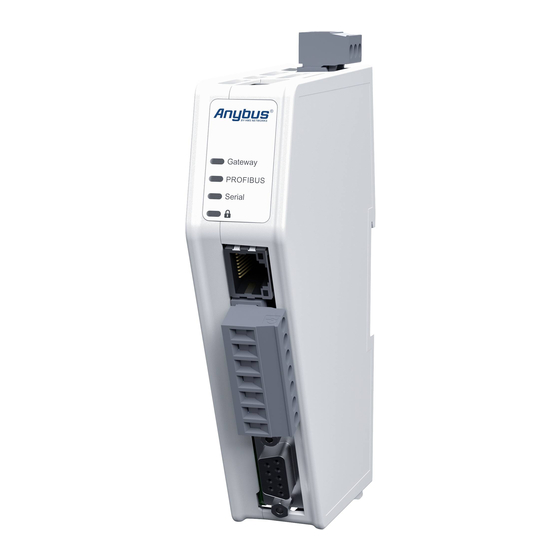
Installation 16 (124) Installation External Parts Power connector 7-pin connector Security switch Label with LED designation Modbus TCP port x 2 Factory reset button Status LEDs Cable tie mount Laser engraved label with product information Configuration port Laser engraved connectors designation DIN rail locking mechanism ®... -
Page 19: Din Rail Mounting
Installation 17 (124) DIN Rail Mounting The equipment must be electrically grounded through the DIN rail for EMC compliance. Make sure that the equipment is correctly mounted on the rail and that the rail is properly grounded. To attach the Communicator on the DIN rail: Insert the upper end of the DIN rail clip into the DIN rail. -
Page 20: Connecting To Modbus Tcp Network
Installation 18 (124) Connecting to Modbus TCP Network Connect the Communicator to your Modbus TCP network. Modbus TCP Connector Description To Do Next Connect the Communicator to the serial subnetwork and to power. Check LED status, refer to Communicator LED Indicators, p. ®... -
Page 21: Connecting To Serial Rs232/Rs485 Subnetwork
Installation 19 (124) Connecting to Serial RS232/RS485 Subnetwork Use minimum 90 oC copper (Cu) wire only. Insert the cable wires into the 7-pin connector and tighten the wire clamp screws. 7-pin connector Signal +5 V OUT RS485- A RS485+ B Signal GND Functional Earth (FE) RS232 Tx Output... -
Page 22: Connecting To Power
Installation 20 (124) Connecting to Power Caution Ensure that the power supply is turned off before connecting it to the equipment. Using the wrong type of power supply can damage the equipment. Ensure that the power supply is connected properly and of the recommended type. Insert the cable wires to the terminal block and tighten the wire clamp screws. -
Page 23: Security Switch
Installation 21 (124) Security Switch After completing the configuration of the Communicator, lock the security switch to prevent unauthorized access to the Communicator built-in web interface. When the security switch is in its locked position, the Communicator built-in web interface can not be accessed and the Communicator can not be configured. -
Page 24: Locking The Cables
Installation 22 (124) Locking the Cables To strain relieve the cables, place a cable tie in the holder and lock the cables. ® ™ SCM-1202-162 1.1 en-US Anybus Communicator User Manual... -
Page 25: Din Rail Demount
Installation 23 (124) DIN Rail Demount Before You Begin Be careful when removing the Communicator from the DIN-rail. If not removed properly, the DIN rail locking mechanism and the product cover can break. Have a flat-blade screwdriver, size 5.5 mm, available. Procedure Remove the Communicator from the DIN Rail: Insert the screwdriver into the Communicator DIN rail locking mechanism. -
Page 26: Configuration Quick Guide
Configuration Quick Guide 24 (124) Configuration Quick Guide This section is intended to give you a short overview of the tasks you need to perform to configure the Communicator. For detailed information, please refer to Communicator Configuration, p. Prepare Configuration 1. - Page 27 Configuration Quick Guide 25 (124) 4. Finding the Communicator on your PC The Communicator default IP address is 192.168.0.10. Option 1 On the PC accessing the Communicator built-in web interface, set a static IP address within the same IP address range as the Communicator IP address.
-
Page 28: Setup New Configuration
Configuration Quick Guide 26 (124) Setup New Configuration Follow these steps to setup a new Communicator configuration. 1. Subnetwork configuration On the Communication page: Select a serial protocol: – Modbus RTU (default) – Custom Request/Response – Custom Produce/Consume For information about the serial protocol types, refer to Serial Protocol Types, p. - Page 29 Configuration Quick Guide 27 (124) 4. High level network configuration On the Modbus TCP page: Use Automatic I/O sizes provided by the subnetwork or choose to set them manually. Enable DHCP server or choose to set a specific IP address. Apply the IP settings.
-
Page 30: Plc Configuration
Configuration Quick Guide 28 (124) PLC Configuration In the Communicator built-in web interface: 1. Export I/O data map When you configure the communication between the Communicator and the PLC, you can use the I/O data map as a specification to ensure that the transactions match. - Page 31 Configuration Quick Guide 29 (124) In the PLC program: 2. Configure the communication Configure the PLC to communicate with the Communicator according to the I/O data map created in the Communicator. ® ™ SCM-1202-162 1.1 en-US Anybus Communicator User Manual...
-
Page 32: Verify Operation
Configuration Quick Guide 30 (124) Verify Operation 1. Apply the configuration When you have completed and verified the configuration, click Apply for the settings to take effect. Verify status and LED indications On the Home page: Monitor the Communicator, network and node status. -
Page 33: Connecting The Communicator
Communicator Configuration 31 (124) Communicator Configuration This section is intended to give you detailed information about the tasks you need to perform to setup a new Communicator configure. For a more brief overview of the configuration steps, please refer to Configuration Quick Guide, p. -
Page 34: Access The Built-In Web Interface From Hms Ipconfig
Communicator Configuration 32 (124) Access the Built-In Web Interface From HMS IPconfig Before You Begin Download the software application HMS IPconfig installation files and user documentation from www.anybus.com/support. The Communicator default IP address is 192.168.0.10. To access the Communicator built-in web interface, ensure that Port 80 TCP is open in your Firewall. This applies to any Firewall between the web browser and the gateway. - Page 35 Communicator Configuration 33 (124) To open the Communicator built-in web interface, click Open web page. Result → You are redirected to the Communicator built-in web interface Home page. ® ™ SCM-1202-162 1.1 en-US Anybus Communicator User Manual...
-
Page 36: Access The Built-In Web Interface From A Web Browser
Communicator Configuration 34 (124) Access the Built-In Web Interface From a Web Browser Before You Begin The Communicator default IP address is 192.168.0.10. To access the Communicator built-in web interface, ensure that Port 80 TCP is open in your Firewall. This applies to any Firewall between the web browser and the gateway. -
Page 37: Communicator Built-In Web Interface Overview
Communicator Configuration 35 (124) Communicator Built-In Web Interface Overview Use the Communicator built-in web interface to configure, maintain and troubleshoot the Communicator. Home View the Communicator, network and node status. Apply After configuration changes are made and verified, press Apply to make the settings take effect. Serial Subnetwork with Nodes. -
Page 38: General Subnetwork Settings
Communicator Configuration 36 (124) General Subnetwork Settings 7.5.1 Communication Serial Protocol Before You Begin Before starting the configuration, select the Serial protocol you want to use: • Modbus RTU: Default setting. Use for serial devices that conform to the Modbus communication specification. - Page 39 Communicator Configuration 37 (124) 7.5.2 Communication Basic Settings Physical standard Specify the physical interface type for the device connected to the Communicator. Select a physical standard from the Physical standard drop-down menu. Setting Value Description RS-232 Physical standard Use RS-232 when one single node is connected to the subnetwork. Default standard RS-485 Use RS-485 when multiple nodes are connected to the subnetwork.
- Page 40 Communicator Configuration 38 (124) Setting Value 57600 baud 115200 baud 128000 baud Data bits Data bits is the number of bits used in the data representation of characters in the telegrams. The rate for Modbus RTU is 8 data bits and can not be changed. Parity Specify if parity should be used to detect errors in the data.
- Page 41 Communicator Configuration 39 (124) 7.5.3 Communication Advanced Settings Inter-Telegram Timeout Mode Settings By default, Inter-telegram timeout mode Default (3.5 characters) is used. This is according the Modbus RTU standard, which advocates the use of a silent period equivalent to 3.5 characters between each message. The silent period is used to find out where one message ends and the next begins.
-
Page 42: About Transaction Templates
Communicator Configuration 40 (124) About Transaction Templates This section applies when the Custom Request/Response or Custom Produce/Consume serial protocol is applied, refer to Communication Serial Protocol, p. 36 7.6.1 Transaction Template Example Custom Request/Response Request/Response transaction template example: The transaction named Read parameter (0x01) consists of a number of frame fields. In the Request field there are three Constants, a Node address and a Checksum field. - Page 43 Communicator Configuration 41 (124) Custom Produce/Consume Produce transaction template example: The transaction named Read Barcode Data Template consists of a number of frame fields. The Transaction type can be Produce or Consume. In this example the Transaction type Consume is selected. In the frame field we have added one Variable data field and two Constant fields.
- Page 44 Communicator Configuration 42 (124) 7.6.2 Transaction Template Types There are two types of transaction templates, Empty template and Modbus template. Empty template When using the Empty template, you start with an empty transaction and build a desired structure by adding and arranging frame fields. For the produce/consume transactions you select;...
- Page 45 Communicator Configuration 43 (124) Modbus templates Modbus templates are available for request/response and transactions. When using the Modbus template, you first select the Modbus template from which you want to start. You can then restructure the transaction by rearranging, adding or removing frame fields. Example, new transaction template based on the Modbus template Read Discrete Inputs: ®...
- Page 46 Communicator Configuration 44 (124) 7.6.3 Frame Field Types Each transaction consists of frame fields which makes up the serial telegram frame. Each frame field specifies how the Communicator shall interpret or generate a particular part of the telegram. The following frame fields are available: Node address Frame field representing the Node address of the Node.
- Page 47 Communicator Configuration 45 (124) Checksum Most serial protocols features some way of verifying that the data has not been corrupted during transfer. The checksum frame field calculates and includes a checksum in a transaction. ® ™ SCM-1202-162 1.1 en-US Anybus Communicator User Manual...
-
Page 48: Build Transaction Templates
Communicator Configuration 46 (124) Build Transaction Templates Before You Begin Ensure that you have applied the Custom Request/Response or Custom Produce/Consume serial protocol, refer to Communication Serial Protocol, p. 7.7.1 Add Transaction Template Procedure Add a transaction template: In the web-interface left sidebar menu, click Transaction templates. To select the template you want to use, click the Add drop-down button. - Page 49 Communicator Configuration 47 (124) ► To add a new empty template without any frame fields, select Empty template. Example, a new empty request/response template is added to the transaction template list: ® ™ SCM-1202-162 1.1 en-US Anybus Communicator User Manual...
- Page 50 Communicator Configuration 48 (124) ► To add a new template based on a standard Modbus transaction, select Modbus templates and then the desired Modbus transaction. Example, a new request/response template based on “Read Coils (1)” is added to the transaction template list: ®...
- Page 51 Communicator Configuration 49 (124) Option for the Custom Produce/Consume Protocol: ► Select Empty produce template or Empty consume template. You can change the Transaction type after the transaction template is added. Example, a new produce template is added to the transaction template list: To apply the settings, click Apply in the web-interface header, and follow the instructions.
- Page 52 Communicator Configuration 50 (124) 7.7.2 Add Frame Fields Procedure In the transaction template list, select a transaction template to add frame fields to. Build the transactions. ► To add frame fields: In the Frame editor frame fields menu, drag and drop the desired frame fields into the drag and drop fields.
- Page 53 Communicator Configuration 51 (124) ► To change the order of the frame fields: Drag and drop the frame fields in the list to change the order. ► To delete a frame field: On the frame field that you want to delete, click the three dots icon .
- Page 54 Communicator Configuration 52 (124) 7.7.3 Configure Frame Field Settings Procedure In the Transaction templates list, select a transaction template to configure. In the Transaction template settings select a Field to configure. → The Field sidebar opens, on the right side of the screen. Configure the Field settings.
- Page 55 Communicator Configuration 53 (124) Limit • Name: You can name the Frame Field to make it easier to identify. • Type: Specify the number of bytes in the frame. Select Byte (1 byte) (Default), Word (2 bytes), Double word (4 bytes). •...
- Page 56 Communicator Configuration 54 (124) Checksum • Name: You can name the Frame Field to make it easier to identify. • Checksum type: Specify the algorithm used to calculate the checksum. Select CRC (CRC-16- IBM) (Default), LRC (ISO 1155:1978), XOR or ADD. •...
- Page 57 Communicator Configuration 55 (124) 7.7.4 Data Delimiter and Subnet Delimiter Options In a variable data object, the length of the data field may vary depending on the type of data being read in a specific case. In order to present the variable data correctly on the corresponding network, the length of the data field must be identified.
- Page 58 Communicator Configuration 56 (124) In the Data delimiter and/or Subnet delimiter drop down menu, select one of the following options: – Byte counter The data packet consists of a length character, indicating the length of the data section, followed by the variable data object itself. In order to copy the exact data size from the transaction message, the length of the variable data object is first identified.
- Page 59 Communicator Configuration 57 (124) 7.7.5 Store Transaction Templates The transaction templates are stored on the Transaction templates page. The transaction templates are available for use on the Nodes & transaction page, when you add transactions to a node. For information on how to add the transaction templates to the nodes, refer to Transaction Settings, p.
-
Page 60: Nodes And Transactions
Communicator Configuration 58 (124) Nodes and Transactions A node represents a single device on the serial subnetwork. Add nodes and set up the communication between the nodes and the client. Before You Begin Obtain user documentation, from the manufacturers of the devices to communicate with, describing available registers and how to address them. - Page 61 Communicator Configuration 59 (124) 7.8.2 Add Node You can add one single Broadcast node. The maximum number of Nodes that can be added is 31. Procedure In the web-interface left sidebar menu, click Nodes & transactions. Click Add node . Select Add broadcast node or Add node.
- Page 62 Communicator Configuration 60 (124) 7.8.3 Node Settings Before You Begin Ensure that the Communicator Basic settings, on the Communication page, match the Node settings. There are no Node settings for the Broadcast node, except Name. Procedure In the nodes list, select a node to configure. ®...
- Page 63 Communicator Configuration 61 (124) Configure the Node settings. Setting Value Description 1 to 247 Node address Node ID, also called node address, is the node’s identity on the subnetwork. The node id is a number between 1 and 247. By default, the node is assigned the next available number. The same node id cannot be used on multiple nodes.
- Page 64 Communicator Configuration 62 (124) 7.8.4 Add Transactions The maximum number of transactions that can be added to a node is 150. In the nodes list, select a node to configure. In the transactions list, click Add. Choose one of the following alternative: When using the Modbus RTU Serial Protocol ►...
- Page 65 Communicator Configuration 63 (124) When using the Request/Response or Produce/Consume Serial Protocol Click Add and select Add from new transaction template. ► → You are redirected to the Transaction template page. A new empty template is added to the Transaction templates list. You need to build the transactions before you can use the template, refer to Build Transaction Templates, p.
- Page 66 Communicator Configuration 64 (124) 7.8.5 Transaction Settings Before You Begin When a custom transaction is selected, the custom transaction template is locked for editing. For Modbus transaction reference guide, refer to Modbus Transactions, p. 121. Procedure Modbus RTU Protocol: Custom Request/Response Protocol: In the nodes list, select a node to configure.
- Page 67 Communicator Configuration 65 (124) Configure the Transaction settings. Setting Value Description Transaction You can name the transaction to make it easier to identify. name Read quantity 1 to 125 Specifies the number of registers to read in the read data field. Appear when Modbus transaction Read Write Multiple Registers (23) is selected.
- Page 68 Communicator Configuration 66 (124) 7.8.6 Activate/Deactivate Transaction The transaction default status is Active. To deactivate/activate a transaction, select the transaction and click the slide toggle. 7.8.7 Duplicate Transaction When you duplicate a transaction, all settings are preserved. To duplicate: • One transaction, select the transaction and click Duplicate.
-
Page 69: High Level Network Settings
Communicator Configuration 67 (124) High Level Network Settings Configure the Modbus TCP network settings. 7.9.1 To Use Automatic I/O Sizes By default, the Communicator is set to use automatic I/O sizes. The size of the input data, Data Size to Modbus TCP, and the output data, Data Size from Modbus TCP, is determined by the subnetwork configuration. - Page 70 Communicator Configuration 68 (124) 7.9.3 To Use DHCP Server By default, the IP settings are provided by the high level network DHCP server. The DHCP enabled checkbox is selected. Default Communicator IP Settings The Communicator comes with the following factory default IP settings: Setting Default value 0.0.0.0...
- Page 71 Communicator Configuration 69 (124) 7.9.4 To Configure IP Settings Manually Deselect the DHCP enabled checkbox. Configure the IP settings. Setting Description IP address The Modbus TCP network IP address in IPv4 dot-decimal notation Subnet mask The Modbus TCP network Subnet mask in IPv4 dot-decimal notation. Gateway address TheModbus TCP network Gateway address in IPv4 dot-decimal notation.
- Page 72 Communicator Configuration 70 (124) 7.9.6 Timeout Time Settings Connection timeout Specify how long a Modbus TCP connection may be idle before it is closed by the Communicator. The default value is 60 seconds Process data active timeout Specify the maximum allowed time between two incoming messages in steps of 10 ms. If this time is exceeded, the high level network is considered to be offline.
-
Page 73: I/O Data Map
Communicator Configuration 71 (124) 7.10 I/O Data Map On the I/O data map page the data communication between the subnetwork (Node) and the high level network (PLC) is mapped. For more information about addressing and register mapping, refer to Addressing and Register Mapping, p. - Page 74 Communicator Configuration 72 (124) 7.10.1 Optimize the I/O Data Map The optimize function is used to automatically remove gaps between the mapping. Optimize remove gaps between the data objects in the map and should be used with care on already commissioned systems. Expected mapping in the PLC may change. If you optimize the I/O data map, the current I/O data map will be overwritten.
- Page 75 Communicator Configuration 73 (124) 7.10.2 Map Area Transactions Order To change the order of the transactions in a map area, drag and drop the desired transaction to a new location. Transactions can not share the same I/O are. If multiple transactions are placed in the same I/O area, the area is highlighted. ®...
- Page 76 Communicator Configuration 74 (124) 7.10.3 Map Area Map area options You must specify the map area to use for each transaction in the I/O data map. Select one of the following Map area options: • Input/Output: The transaction data is sent/recieved to/from the high level network. •...
- Page 77 Communicator Configuration 75 (124) 7.10.4 Trigger Byte Trigger byte is used to enable/disable the trigger functionality for the response. When Trigger byte is enabled, the Communicator increases the trigger byte by one when the Communicator receives new data from the subnetwork. The Trigger byte is stored in the Data from Modbus TCP area or the General area.
- Page 78 Communicator Configuration 76 (124) 7.10.5 Endian Swap In most cases, no endian swap is needed, as both Modbus TCP and Modbus-RTU use big-endian by default. Big-endian The big-endian format places the most significant byte of the data at the byte with the lowest memory address.
- Page 79 Communicator Configuration 77 (124) 7.10.6 Offline Option Offline mode is used to define what data to send if the network connection or connection with a specific node is lost. You must specify the offline mode to use for each transaction on the I/O data map. Select one of the following Offline options: •...
- Page 80 Communicator Configuration 78 (124) 7.10.7 Live List By default Live list is disabled. When Live list is enabled, the first four bytes of process data on the Modbus TCP network contain the live list. The Live list holds 32 bits. Each bit in the Live list can hold the status for a total of 32 nodes connected to the Communicator.
- Page 81 Communicator Configuration 79 (124) 7.10.8 Data Exchange Control By default Data exchange control is disabled. When Data exchange control is enabled, the first four bytes of process data on the Modbus TCP network contain the data exchange control. The Data exchange control holds 32 bits. Each bit in the Data exchange control can be used to enable/disable data exchange for individual nodes on the subnetwork.
-
Page 82: Apply Configuration
Communicator Configuration 80 (124) 7.11 Apply Configuration Before You Begin When you apply the configuration, any existing configuration is overwritten. Disconnect the Communicator from the Modbus TCP network Before you can apply the configuration, ensure that there is no active communication on the Modbus TCP network where the Communicator is connected. - Page 83 Communicator Configuration 81 (124) If you have made changes to the IP settings you are prompted to apply these settings. To apply the IP settings, click Apply IP settings. ® ™ SCM-1202-162 1.1 en-US Anybus Communicator User Manual...
-
Page 84: Use An Existing Configuration
Communicator Configuration 82 (124) 7.12 Use an Existing Configuration When you have configured a Communicator and want to use the same settings to configure additional Communicators, do the following. Procedure In the built-in web-interface of the Communicator with the configuration you want to use: On the Files &... -
Page 85: Plc Configuration
PLC Configuration 83 (124) PLC Configuration Export I/O Data Map When configuring the communication between the PLC and the nodes on the subnetwork, use the I/O data map as a specification to ensure that the transactions match. In the Communicator built-in web-interface: On the I/O data map page you can exported the I/O data map in an Excel XLS file, where all the nodes and transactions are listed. -
Page 86: Addressing And Register Mapping
PLC Configuration 84 (124) Addressing and Register Mapping 8.2.1 Data From Modbus TCP Network to Serial-Subnet Process data offset Coil address Holding register 0x0000 — 0x001 0x0000 — 0x000F 0x0000 0x0002 — 0x0003 0x0010 — 0x001F 0x0001 0x05D8 — 0x05D9 0x2EC0 —... -
Page 87: Verify Operation
Verify Operation 85 (124) Verify Operation Before You Begin Ensure that the Communicator is connected to your PC, to a power supply and to the OT network. Refer to Installation, p. Communicator Status Monitor On the Home page, you can get a quick overview of the network and the Communicator operating status. - Page 88 Verify Operation 86 (124) Status Symbols Symbol Description Internal error has occurred and operation cannot be guaranteed. Out of Specification. Check Function: • Initial state where non network components are started and configured. • Network startup in progress. • Invalid configuration detected. Normal operation.
-
Page 89: Communicator Led Indicators
Verify Operation 87 (124) Communicator LED Indicators Before you can verify operation you must configure the Communicator. LED A LED B LED C LED D Operation Status Gateway status Modbus TCP Server Subnetwork Security switch No power No power/Exception/No No power/Exception/ No power/Security IP address Subnetwork not... -
Page 90: Modbus Tcp Led Indicators
Verify Operation 88 (124) Modbus TCP LED Indicators LED A Function No link (or no power) Green Link (100 Mbit/s) established Green, flashing Activity (100 Mbit/s) Yellow Link (10 Mbit/s) established Yellow, flashing Activity (10 Mbit/s) LED B Function Not used ®... -
Page 91: Use Cases
Use Cases 89 (124) Use Cases 10.1 Temperature Regulator - Modbus RTU Use Case 10.1.1 About the Use Case The purpose of this use case is to explain how to use the Modbus RTU serial protocol. In this use case we use the Communicator to enable data exchange between an Temperature Regulator and a PLC. - Page 92 Use Cases 90 (124) 10.1.3 Choose Serial Protocol Type The Temperature Regulator is using a request/response protocol to access parameters addressed with index and sub index. ► On the Serial RS232/485 page, select Modbus RTU. 10.1.4 Set Up Serial Communication Set up the communication between the Communicator and the Temperature Regulator.
- Page 93 Use Cases 91 (124) 10.1.5 Set Up the Node Add a node and select it. In Node settings configure the node with the following settings: Node settings Value Slave address Name Temp Regulator Timeout time 1000 ms Reconnection time 1000 ms Retries Register Address format...
- Page 94 Use Cases 92 (124) 10.1.6 Set Up Transactions Set up the communication between the node and the master. In this example, the communication between the Temperature Regulator and the PLC. The Temperature Regulator has two Modbus transactions: • One registers holding the setpoint temperature. •...
- Page 95 Use Cases 93 (124) Configure the actual temperature transaction: To add a second transaction, click Add. Select the transaction to configure. In the transaction sidebar, on the right side of the screen. Enter values for the transaction settings. Actual temperature transaction settings: Setting Description Value...
- Page 96 Use Cases 94 (124) 10.1.7 Check the I/O Data Map The transactions to and from the Temperature Regulator are mapped as follows in the I/O data map page. Address Data to Modbus TCP 0–1 Setpoint temperature from Modbus TCP to the Temperature Regulator. Address Data from Modbus TCP 0–1...
-
Page 97: Ac Motor Drive - Custom Request/Response Use Case
Use Cases 95 (124) 10.2 AC Motor Drive - Custom Request/Response Use Case 10.2.1 About the Use Case The purpose of this use case is to explain how to use the Custom Request/Response serial protocol. In this use case we use the Communicator to enable data exchange between an AC motor, of the type My Drive, and a PLC. - Page 98 Use Cases 96 (124) 10.2.3 Choose Serial Protocol Type My Drive is using a request/response protocol to access parameters addressed with index and sub index. On the Serial RS232/485 page, select Custom Request/Response. ► 10.2.4 Set Up Serial Communication Set up the communication between the Communicator and My Drive. In the Serial RS232/485 page, configure the Communication settings.
- Page 99 Use Cases 97 (124) 10.2.5 Create Transaction Templates All frames are verified using a CRC-16-IBM checksum. My Drive is using a request/response protocol to access parameters addressed with index and sub index. Map up control word, speed from Modbus TCP to My Drive and status word and actual speed from the drive to Modbus TCP.
- Page 100 Use Cases 98 (124) In the Frame editor Response area, add six frame fields with the following settings: Response frame fields Name Frame field Bytes/ Type/ Endianess Fixed field Value Length Checksum type Constant Function code 1 Byte Byte Node address Node ID Min 0 Constant...
- Page 101 Use Cases 99 (124) Create Write Parameter (0x02) The Communicator writes values delivered from the PLC to the My Drive node. Add an Empty template and select it. Name the template Write parameter (0x02). In the Frame editor Request area, add six frame fields with the following settings: Request frame fields Name Frame field...
- Page 102 Use Cases 100 (124) 10.2.6 Set Up Node and Transactions Add a node and select it. In Node settings configure the node with the following settings: Node settings Value Node address My Drive is set up as a node with Node address 1. Name My Drive Timeout time...
- Page 103 Use Cases 101 (124) 10.2.7 Check the I/O Data Map The control word, speed from Modbus TCP to My Drive and status word and actual speed from My Drive to Modbus TCP are mapped as follows in the I/O data map page. Control word and speed from Modbus TCP to My Drive Address Data to Modbus TCP...
-
Page 104: Barcode Scanner - Custom Produce/Consume Use Case
Use Cases 102 (124) 10.3 Barcode Scanner - Custom Produce/Consume Use Case 10.3.1 About the Use Case The purpose of this use case is to explain how to use the Custom Produce/Consume serial protocol. In this use case we use the Communicator to enable data exchange between an Barcode Scanner and a PLC. - Page 105 Use Cases 103 (124) 10.3.3 Choose Serial Protocol Type The Barcode Scanner is using a produce/consume protocol to access parameters addressed with index and sub index. On the Serial RS232/485 page, select Custom Produce/Consume. ► 10.3.4 Set Up Serial Communication Set up the communication between the Communicator and the Barcode Scanner.
- Page 106 Use Cases 104 (124) 10.3.5 Create Transaction Templates Create Read Barcode Data Parameter Before You Begin The Communicator reads values delivered from to the Barcode Scanner node on to the PLC. The Barcode Scanner sends data whenever it is available, without any request or handshake from the Communicator.
- Page 107 Use Cases 105 (124) Procedure Add an Empty consume template and select it. Name the template Read Barcode Data. In the Frame editor, add four frame field with the following settings: Consume frame fields Frame Name Type Process Value Fixed field Maximum Subnet fields payload...
- Page 108 Use Cases 106 (124) Set Up Node and Transactions Add a node and select it. In Node settings configure the node with the following settings: Node settings Value Node address The Barcode Scanner is set up as a node with Node address 1.
-
Page 109: Maintenance
Maintenance 107 (124) Maintenance 11.1 Configuration File Handling 11.1.1 Export Configuration You can export the current configuration, in order to import and use the same settings to configure additional Communicators. To export a configuration file: In Files & firmware, click Export. →... - Page 110 Maintenance 108 (124) 11.1.2 Import Configuration To easily configure multiple Communicators with the same settings, you can import a configuration file. Before You Begin Importing a configuration replaces the current applied configuration. Supported file format is .conf. Procedure Import configuration file: On the Files &...
-
Page 111: Clear And Revert Configuration
Maintenance 109 (124) 11.2 Clear and Revert Configuration You can restore all settings in a configuration to the default settings. Procedure To clear the configuration: On the Files & firmware page, click Clear. In the Confirm clear window, click Clear. To apply the change, click Apply in the web-interface header, and follow the instructions. - Page 112 Maintenance 110 (124) 11.3.2 Firmware and Configuration Compatibility Compatibility after firmware upgrade Current configuration is still compatible after upgrading the firmware. Compatibility after firmware downgrade Compatibility after a firmware downgrade can not be guaranteed. The current configuration may use features not available in the older firmware version. ®...
- Page 113 Maintenance 111 (124) 11.3.3 Firmware File Validation Before the firmware file is imported into the system, the firmware upgrade function perform a validation of the file, to ensure that: • the firmware is compatible with the Communicator hardware • the firmware is suited for the product •...
-
Page 114: Troubleshooting
Troubleshooting 112 (124) Troubleshooting 12.1 Diagnostics 12.1.1 Serial RS-232/485 Data Monitor On the Serial RS-232/485 page you can monitor how the data flow between the nodes and the gateway changes over time. The table can contain at most 10000 messages. When the limit is reached, the oldest messages are discarded when new messages are added. - Page 115 Troubleshooting 113 (124) 12.1.2 Event Log How To Analyze the Information The log follows the FIFO principle, first in and first out. The oldest (first) value is processed first. Time (d:hh:mm: The date and time when the event occurred. ss.ms) Message A brief description of the event.
- Page 116 Troubleshooting 114 (124) 12.1.3 LED Status On the Home page, you can remotely monitor the Communicator LED status. For information about the LED indication, refer to Communicator LED Indicators, p. ® ™ SCM-1202-162 1.1 en-US Anybus Communicator User Manual...
-
Page 117: Reset To Factory Settings
Troubleshooting 115 (124) 12.2 Reset to Factory Settings Before You Begin Factory reset will reset any on site made configuration changes and set the Communicator to the same state as leaving HMS production. If the Firmware has been updated, factory reset will revert the Communicator configuration to initial state after the update. - Page 118 Troubleshooting 116 (124) While holding the reset button, reconnect the Communicator to power. Release the reset button. → The Communicator enters Exception state. Reboot the Communicator. Result → When the Communicator has successfully rebooted, the Communicator configuration is reset to the factory default configuration or the current configuration after firmware upgrade.
-
Page 119: Firmware Upgrade Error Management
Troubleshooting 117 (124) 12.3 Firmware Upgrade Error Management If the firmware update process is interrupted or if the power is lost during the update process, the Communicator goes into fallback mode. The last working firmware is still available on the flash, but it is not active. To complete the interrupted firmware update: Disconnect the Communicator from power. - Page 120 Troubleshooting 118 (124) Leave the Communicator for 10 minutes. The Gateway status led indicator flashes red and green until the firmware upgrade is completed. Result → The Communicator recover and return to normal operation. To check LED status, refer to Communicator LED Indicators, p.
-
Page 121: Support
Troubleshooting 119 (124) 12.4 Support 12.4.1 Support Package Before you create a ticket for technical support, generate a support package. The support package contain information about what has occurred and will help the Anybus technical support team resolve the support case as quickly and efficiently as possible. Support Package Content The information in the support package are available to open and read, the files are not locked or encrypted. -
Page 122: Technical Data
Technical Data 120 (124) Technical Data 13.1 Technical Specifications ABC3028-A Article identification Communication connector RJ45 x 2 RJ45 Configuration connector Serial connector 7-pin screw connector Power connector 3-pin screw connector Power supply 12-30 VDC Reverse voltage protection and short circuit protection Power consumption Typical: 160 mA @ 24 V Max: 400 mA @ 12 V... -
Page 123: A Reference Guides
Appendix A: Reference Guides 121 (124) Reference Guides About Input Registers and Holding Registers Modbus data is most often read and written as registers which are 16-bit pieces of data. Holding registers and Input registers are both 16-bit registers. Input registers Input registers can only be read. -
Page 124: Modus Exception Codes
Appendix A: Reference Guides 122 (124) Modus Exception Codes Name Exception Code Description Illegal Function The server does not recognize or permit the function code. Illegal Data Address The data address (register, discrete input or coil number) is not an permitted address for the server. -
Page 125: Rs485/Rs232 Electrical Connection
Appendix A: Reference Guides 123 (124) RS485/RS232 Electrical Connection A.6.1 RS485 Typical Connection A.6.2 RS232 Typical Connection ® ™ SCM-1202-162 1.1 en-US Anybus Communicator User Manual... - Page 126 last page © 2021 HMS Industrial Networks Box 4126 300 04 Halmstad, Sweden info@hms.se SCM-1202-162 1.1 en-US / 2021-07-05 / 22950...
Need help?
Do you have a question about the Anybus Communicator ABC3028 and is the answer not in the manual?
Questions and answers