
Related Manuals for HMS Networks Anybus Wireless Bolt LTE AWB1504


Summary of Contents for HMS Networks Anybus Wireless Bolt LTE AWB1504
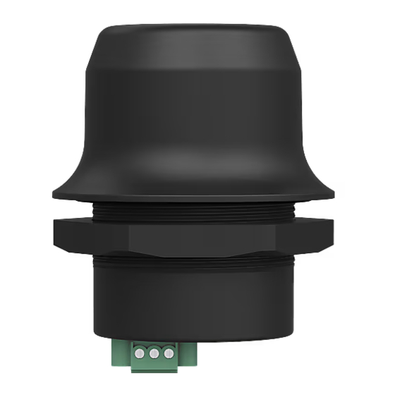
- Page 1 ENGLISH ® ™ Anybus Wireless Bolt LTE USER MANUAL SCM-1202-164 Version 1.5 Publication date 2024-01-03...
- Page 2 The information in this document shall therefore not be construed as a commitment on the part of HMS Networks and is subject to change without notice. HMS Networks makes no commitment to update or keep current the information in this document.
-
Page 3: Table Of Contents
® ™ Anybus Wireless Bolt LTE Table of Contents 1. Preface ..........................1 1.1. About This Document ......................1 1.2. Document Conventions ..................... 1 1.3. Trademarks ........................2 2. Safety ............................ 3 2.1. General Safety ......................... 3 2.2. Intended Use ........................3 3. - Page 4 ® ™ Anybus Wireless Bolt LTE 7. Verify Operation ........................39 7.1. System Settings and Network Connection ................39 7.2. LED Status Indication ......................40 8. Maintenance ......................... 41 8.1. Firmware Update ......................41 8.2. Set Administrator Password ....................43 8.3.
-
Page 5: Preface
® ™ Preface Anybus Wireless Bolt LTE 1. Preface 1.1. About This Document ® ™ This document describes how to install and configure Anybus Wireless Bolt LTE For additional documentation and software downloads, FAQs, troubleshooting guides and technical support, please visit www.anybus.com/support. 1.2. -
Page 6: Information Symbols
Helpful advice and suggestions. 1.3. Trademarks ® ™ Anybus is a registered trademark and Wireless Bolt LTE is a trademark of HMS Networks AB. All other trademarks are the property of their respective holders. Page 2 of 62 SCM-1202-164 Version 1.5... -
Page 7: Safety
® ™ Safety Anybus Wireless Bolt LTE 2. Safety 2.1. General Safety CAUTION This equipment emits RF energy in the ISM (Industrial, Scientific, Medical) band. Make sure that all medical devices used in proximity to this equipment meet appropriate susceptibility specifications for this type of RF energy. -
Page 8: Preparation
® ™ Anybus Wireless Bolt LTE Preparation 3. Preparation 3.1. Support and Resources For additional documentation and software downloads, FAQs, troubleshooting guides and technical support, please visit www.anybus.com/support. Have the product article number available, to search for the product specific support web page. You find the product article number on the product cover. -
Page 9: Firewall And Routing
® ™ Firewall and Routing Anybus Wireless Bolt LTE 3.6. Firewall and Routing There are routing options set for the system. By default, the firewall allows routing of: • Outgoing traffic for TCP, UDP and ICMP (for IPv4 only). • Incoming traffic for already established connections only. For other possible configurations, see NAT/Port Forward Settings (page 29). -
Page 10: Installation
® ™ Anybus Wireless Bolt LTE Installation 4. Installation 4.1. Install SIM Card NOTE Supported SIM card types are Nano SIM for IoT and M2M, for data communication, as well as standard mobile phone Nano SIM. Figure 1. Insert SIM card To connect Bolt LTE to a cellular data network, install a cellular SIM card: Insert a SIM card into the Bolt LTE SIM card holder. -
Page 11: Mechanical Installation
® ™ Mechanical Installation Anybus Wireless Bolt LTE 4.2. Mechanical Installation Placement • The device is intended to be mounted on top of a machine or cabinet through an M50 (50.5mm) hole using the included sealing ring and nut. • The top mounting surface, in contact with the sealing, must be flat with a finish equivalent to Ra 3.2 or finer and cleaned and free from oils and greases. -
Page 12: Connect To Power Over Ethernet (Poe)
® ™ Anybus Wireless Bolt LTE Connect to Power Over Ethernet (PoE) 4.3. Connect to Power Over Ethernet (PoE) Before You Begin IMPORTANT Connecting the Bolt LTE to PoE and DC power simultaneously may result in a current loop that could damage both the power sources and the Bolt LTE. - Page 13 ® ™ Connect to Power Over Ethernet (PoE) Anybus Wireless Bolt LTE RJ45 Ethernet PoE Connector Table 1. RJ45 Ethernet PoE Connector pinning Data Positive power from alt. A PSE Negative power from alt. A PSE (with pin 6) Positive power from alt. B PSE Negative power from alt.
-
Page 14: Connect To Power And Ethernet
® ™ Anybus Wireless Bolt LTE Connect to Power and Ethernet 4.4. Connect to Power and Ethernet Before You Begin CAUTION Connecting power with reverse polarity or using the wrong type of power supply may damage the equipment. Make sure that the power supply is connected correctly and of the recommended type. IMPORTANT Connecting the Bolt LTE to PoE and DC power simultaneously may result in a current loop that could damage both the power sources and the Bolt LTE. - Page 15 ® ™ Connect to Power and Ethernet Anybus Wireless Bolt LTE Procedure Connect to power and Functional Earth (FE) Figure 5. Power and Functional Earth (FE) Connect Bolt LTE Power connector to a power supply. Connect Bolt LTE Power connector to Functional Earth (FE). Table 2.
- Page 16 ® ™ Anybus Wireless Bolt LTE Connect to Power and Ethernet Connect to Ethernet Connect the Bolt LTE to Ethernet. Figure 6. Connect to Ethernet Page 12 of 62 SCM-1202-164 Version 1.5...
-
Page 17: Configuration
® ™ Configuration Anybus Wireless Bolt LTE 5. Configuration 5.1. Before You Begin Configuration By default, the Bolt LTE APN Assignment is set to automatically search for the SIM card APN setting and assign it to the Bolt LTE. In cases where no additional configuration of the settings in the Bolt LTE built-in web interface is required, see Setting Up Bolt LTE with Automatic APN Assignment (page 34). -
Page 18: Access The Built-In Web Interface
® ™ Anybus Wireless Bolt LTE Access the Built-In Web Interface 5.3. Access the Built-In Web Interface 5.3.1. Required IP Address Settings To be able to access the Bolt LTE built-in web interface you may need to adjust the IP settings, choose one of the following methods. -
Page 19: Login To The Built-In Web Interface
® ™ Access the Built-In Web Interface Anybus Wireless Bolt LTE 5.3.2. Login to the Built-In Web Interface The Bolt LTE built-in web interface can be accessed from a standard web browser. Before You Begin IMPORTANT Before installing the Bolt LTE on a network, change the Bolt LTE default username and password. NOTE The Bolt LTE comes with a default username and password. - Page 20 ® ™ Anybus Wireless Bolt LTE Access the Built-In Web Interface Figure 10. System Overview page Page 16 of 62 SCM-1202-164 Version 1.5...
-
Page 21: Bolt Lte Built-In Web Interface
® ™ Bolt LTE Built-In Web Interface Anybus Wireless Bolt LTE 5.4. Bolt LTE Built-In Web Interface The Bolt LTE built-in web interface is used to configure the Bolt LTE system settings as well as for diagnostics and maintenance. The System Overview page shows the current settings and network connection status. Figure 11. -
Page 22: Factory Default Settings
® ™ Anybus Wireless Bolt LTE Factory Default Settings 5.5. Factory Default Settings Bolt LTE comes with the following factory default settings. Table 3. Bolt LTE default settings IP Assignment Static IP Address 192.168.0.98 Subnet Mask 255.255.255.0 Default Gateway 192.168.0.98 Internal DHCP Server Enabled Network Type... -
Page 23: Ethernet Settings
® ™ Ethernet Settings Anybus Wireless Bolt LTE 5.6. Ethernet Settings IP Settings Figure 12. Ethernet Settings page, default IP Settings with Internal DHCP Server Enabled To Change the Bolt LTE IP Address NOTE The default Bolt LTE static IP address is 192.168.0.98. Procedure In the IP Address field, enter the new IP address. - Page 24 ® ™ Anybus Wireless Bolt LTE Ethernet Settings IP Address Range NOTE When the Bolt LTE is enabled, you can still use static IP addresses within the remaining IP address range. The devices assigned to these IP addresses can set Bolt LTE as the default gateway and DNS server.
-
Page 25: Cellular Settings
® ™ Cellular Settings Anybus Wireless Bolt LTE 5.7. Cellular Settings Before You Begin When you are going to connect Bolt LTE to a cellular network, ensure that you have installed a SIM card in the Bolt LTE SIM card holder. Refer to Install SIM Card (page 5.7.1. -
Page 26: Apn Settings
® ™ Anybus Wireless Bolt LTE Cellular Settings 5.7.2. APN Settings Automatic APN Assignment IMPORTANT An APN automatically derived from SIM card identification may not give full access to the cellular network. Follow your network operator's guidelines. IMPORTANT By default, Bolt LTE is set to automatically search for the SIM card APN setting. If a general APN string is available for the network operator, it will be set as the APN Assignment. -
Page 27: Sim Pin And Puk Settings
® ™ Cellular Settings Anybus Wireless Bolt LTE APN Authentication By default, APN Authentication is set to No. When enabled, PAP method is used. NOTE APN Authentication is to be configured only if your carrier has setup APN (Access Point Name) with username and password. - Page 28 ® ™ Anybus Wireless Bolt LTE Cellular Settings SIM Card PUK Code Figure 18. PUK code is required If you have entered the wrong PIN code three times in a row, the SIM card is blocked. To unlock it, you must enter a new PIN code and the SIM card PUK (PIN Unlock Key) code. Check the number of attempts to enter the correct PUK code that applies to your operators' SIM cards.
-
Page 29: Enable Sms Api
® ™ Cellular Settings Anybus Wireless Bolt LTE 5.7.4. Enable SMS API The Bolt LTE SMS application can receive, parse and respond to SMS. By default, Handle incoming SMS is set to Externally via API. Sending of SMS(es) is done by intermittently using the SMS REST API. The Bolt LTE does not parse or respond to the SMS(es). -
Page 30: Enable Sms Communication
® ™ Anybus Wireless Bolt LTE Cellular Settings 5.7.5. Enable SMS Communication The Bolt LTE SMS application can receive, parse and respond to status information SMS. By default, Handle incoming SMS is set to Externally via API. Procedure On the Cellular Settings page, SMS Settings: Figure 21. -
Page 31: To Send Sms Messages To The Bolt Lte
® ™ Cellular Settings Anybus Wireless Bolt LTE In the Site name field, you can enter a label to identify the Bolt LTE. The Site name is included in the automatically generated welcome SMS sent from the Bolt LTE. Click Save and Reboot. To verify the phone number, the Bolt LTE sends an automatically generated welcome SMS to the handheld device with the specified phone number. -
Page 32: Notification Sms
® ™ Anybus Wireless Bolt LTE Cellular Settings Result Depending on which command is sent, the Bolt LTE returns a message containing information or a prompt with instructions on how to continue. For information about the available commands, see SMS Commands and Returns (page 54) Example 4. -
Page 33: Nat/Port Forward Settings
® ™ NAT/Port Forward Settings Anybus Wireless Bolt LTE 5.8. NAT/Port Forward Settings Before You Begin NAT/Port forward is used to allow incoming traffic from an external (cellular mobile-radio) network access to a device IP address on the internal (Ethernet) network. The Source Filter setting is used to prevent unauthorized traffic on the local network. -
Page 34: Vpn Settings
® ™ Anybus Wireless Bolt LTE VPN Settings 5.9. VPN Settings Before You Begin OpenVPN Client is used to secure and encrypt the data sent between the Bolt LTE and a remote VPN Server over cellular network. By default, OpenVPN Client is set to Disabled. OpenVPN Configuration File Ensure you have downloaded a OpenVPN configuration (.ovpn) file from you VPN provider. -
Page 35: Positioning Settings
® ™ Positioning Settings Anybus Wireless Bolt LTE 5.10. Positioning Settings Before You Begin Use the positioning function to locate the position of the Bolt LTE. For example, the Bolt LTE position is available and can be retrieved from the Bolt LTE via REST API. By default, Positioning Service is Disabled. -
Page 36: Setting Up With Rest Commands
® ™ Anybus Wireless Bolt LTE Setting Up with REST Commands 5.11. Setting Up with REST Commands How To Use REST Commands For information about the supported REST commands and how to use them, refer to the REST Commands Reference Guide at www.anybus.com/support. Use/Test REST Commands From a Web Browser For information about the supported REST commands, refer to the REST Commands Reference Guide at www.anybus.com/support. -
Page 37: Lock Configuration
® ™ Lock Configuration Anybus Wireless Bolt LTE 5.12. Lock Configuration When configuration is locked, you can still access and use the Bolt LTE built-in web interface, but the settings cannot be configured. Figure 26. System page, Lock Configuration To lock the configuration: Navigate to the System page. -
Page 38: Use Cases
® ™ Anybus Wireless Bolt LTE Use Cases 6. Use Cases 6.1. Setting Up Bolt LTE with Automatic APN Assignment Before You Begin By default, the Bolt LTE APN Assignment is set to automatically search for the SIM card APN setting and assign it to the Bolt LTE. - Page 39 ® ™ Setting Up Bolt LTE with Automatic APN Assignment Anybus Wireless Bolt LTE Connect the Bolt LTE to a power supply and to Functional Earth (FE). Connect to Power and Ethernet (page 10) To verify the connection status, check the Bolt LTE RJ45 LED indicators. LED Status Indication (page 40) Connect an Ethernet cable between the Bolt LTE and the device to be connected to the internet.
-
Page 40: Set Up Bolt Lte As An Internet Router
® ™ Anybus Wireless Bolt LTE Set Up Bolt LTE as an Internet Router 6.2. Set Up Bolt LTE as an Internet Router Before You Begin Use Bolt LTE as an internet router to connect machines, controllers or other devices to internet. NOTE The Bolt LTE comes with a default username and password. - Page 41 ® ™ Set Up Bolt LTE as an Internet Router Anybus Wireless Bolt LTE Verify Internet Connection Bolt LTE should now be connected to internet. NOTE Depending on the mobile network operator and network type, it can take up to 10 minutes the first time Bolt LTE is connecting to internet.
-
Page 42: Set Up Bolt Lte With Ulpm Rest Command
® ™ Anybus Wireless Bolt LTE Set Up Bolt LTE with ULPM REST Command 6.3. Set Up Bolt LTE with ULPM REST Command NOTE The Bolt LTE variant for the US market does not support the ULPM REST Command. You can use Bolt LTE as an internet router with Ultra Low Power Mode (ULPM) to save electrical energy. Devices using other power sources than grid connected power, such as devices powered by batteries and/or solar panels, benefit from using ULPM. -
Page 43: Verify Operation
® ™ Verify Operation Anybus Wireless Bolt LTE 7. Verify Operation 7.1. System Settings and Network Connection On the System Overview page, verify the settings and network connection status. Figure 31. Example, Verify Settings and Network Connection SCM-1202-164 Version 1.5 Page 39 of 62... -
Page 44: Led Status Indication
® ™ Anybus Wireless Bolt LTE LED Status Indication 7.2. LED Status Indication Figure 32. RJ45 LED indicators LED A – LINK/ACTIVITY Function No Ethernet link Yellow 10 Mb/s Ethernet link established Yellow, flashing 10 Mb/s Ethernet activity Green 100 Mb/s Ethernet link established Green, flashing 100 Mb/s Ethernet activity LED B –... -
Page 45: Maintenance
® ™ Maintenance Anybus Wireless Bolt LTE 8. Maintenance 8.1. Firmware Update Before You Begin NOTE The configuration settings are not affected when updating firmware. Download the Firmware Update File Download the firmware update file from www.anybus.com/support. Connect Bolt LTE to your computer, refer to Connect to PC and Power (page 13). - Page 46 ® ™ Anybus Wireless Bolt LTE Firmware Update Firmware update progress Figure 34. Firmware Update, Transferring file • The progress bar, Transferring file, indicates the progress of the file transfer. Status messages show the progress of the firmware update stages. •...
-
Page 47: Set Administrator Password
® ™ Set Administrator Password Anybus Wireless Bolt LTE 8.2. Set Administrator Password IMPORTANT Before installing the Bolt LTE on a network, change the Bolt LTE default username and password. NOTE The Bolt LTE comes with a default username and password. The default username is admin, written in lowercase letters. -
Page 48: Restore Settings From Backup File
® ™ Anybus Wireless Bolt LTE Reboot System 8.3.2. Restore Settings From Backup File IMPORTANT When you restore settings from a backup file, all the current settings except the Administrator Password are overwritten by the settings loaded from the backup file. Figure 37. -
Page 49: Troubleshooting
® ™ Troubleshooting Anybus Wireless Bolt LTE 9. Troubleshooting 9.1. Logs The System Log contain useful information for troubleshooting issues that may occur in the system. The Log file contains additional information, such as messages from the kernel, drivers, init scripts, services, and applications. -
Page 50: Diagnostics
® ™ Anybus Wireless Bolt LTE Diagnostics 9.2. Diagnostics Figure 40. Diagnostics page 9.2.1. Cellular Diagnostics Monitor Signal Strength and Quality You can use the diagnostics information when planning the installation of Bolt LTE. If Bolt LTE is to be placed in a fixed installation and there are several possible locations to choose between, it is viable to monitor the signal strength and quality in the intended locations. -
Page 51: Network Diagnostics
® ™ Diagnostics Anybus Wireless Bolt LTE 9.2.3. Network Diagnostics NOTE If Bolt LTE is installed on a private cellular network, the methods are limited according to the restrictions of the private network. NOTE The methods are useful when evaluating the connection on the cellular network. Complete the evaluation by performing tests from the connected device on the LAN network. - Page 52 ® ™ Anybus Wireless Bolt LTE Diagnostics Example 7. Ping response message from target 8.8.8.8 Example 8. Nslookup response message from target www.anybus.com Example 9. Wget response message from target Speedtest Page 48 of 62 SCM-1202-164 Version 1.5...
-
Page 53: Data Connection Termination
® ™ Data Connection Termination Anybus Wireless Bolt LTE Example 10. Wget response message from target webpage Response message with elapsed time between the request being sent to the Target and the response being returned. 9.3. Data Connection Termination Figure 41. System Overview page, Data Connection status Yes On the System Overview page, Data Connection status Yes is picked up from the underlying system and is not tested for data transfer. -
Page 54: Find The Bolt Lte Ip Address
® ™ Anybus Wireless Bolt LTE Find the Bolt LTE IP Address 9.4. Find the Bolt LTE IP Address You can use the software application HMS IPconfig to find the Bolt LTE IP address. Example 11. Device IP address detected in HMS IPconfig Figure 42. -
Page 55: Factory Reset Using The Reset Button
® ™ Reset and Recovery Anybus Wireless Bolt LTE 9.5.2. Factory Reset Using the Reset Button IMPORTANT Factory Reset will result in the loss of all configuration settings and logs. Ensure that the Bolt LTE is powered on and running. Figure 44. -
Page 56: Factory Reset Using The Built-In Web Interface
® ™ Anybus Wireless Bolt LTE Reset and Recovery 9.5.3. Factory Reset Using the Built-In Web Interface IMPORTANT Factory Reset will result in the loss of all configuration settings and logs. Figure 46. System page, System Actions Click Factory Reset. To confirm factory reset, click OK. -
Page 57: Technical Data
® ™ Technical Data Anybus Wireless Bolt LTE 10. Technical Data 10.1. Technical Specifications Order code EMEA: AWB1500 EMEA: AWB1501 Americas: AWB1502 Americas: AWB1503 Japan: AWB1504 Japan: AWB1505 Color Black White top and black base Operating temperature Shadow: -40 to +65 °C Shadow: -40 to +65 °C Direct sunlight: -40 to +45 °C Direct sunlight: -40 to +65 °C... -
Page 58: Reference Guides
® ™ Anybus Wireless Bolt LTE Reference Guides 11. Reference Guides 11.1. SMS Commands and Returns The SMS Commands and Returns Reference Guide only applies to the SMS communication setting Internally via SMS, see Enable SMS Communication (page 26). For in-depth information about the commands, see the REST Commands Reference Guide at www.anybus.com/support. -
Page 59: Available Commands
® ™ SMS Commands and Returns Anybus Wireless Bolt LTE 11.1.1. Available Commands Command: help Returns, list with available commands: • help • id • info • ip • mac • mast • phys • ping destination • pos • reboot •... -
Page 60: Sim Card Id
® ™ Anybus Wireless Bolt LTE SMS Commands and Returns 11.1.2. SIM Card ID Get information about the SIM card installed in the Bolt LTE. Command: id Returns: • Integrated circuit card identifier iccid • International mobile subscriber identity imsi •... -
Page 61: System Information
® ™ SMS Commands and Returns Anybus Wireless Bolt LTE 11.1.3. System Information Command: info Returns: • The time for which the Bolt LTE has been running: uptime • RAT (Radio Access Technology) network type: rat • Access technology of the serving cell: rat_specific •... -
Page 62: Ip Address
® ™ Anybus Wireless Bolt LTE SMS Commands and Returns 11.1.4. IP Address Command: ip Returns: • cellular_ip • cellular_gateway • eth0_ip • eth0_mask Example 15. Get the Bolt LTE IP addresses Message to Bolt LTE: my_access_code ip Reply message from Bolt LTE: cellular_ip: 100.12.345.67 cellular_gateway: 100.12.345.68 eth0_ip: 123.45.678.9.11... -
Page 63: Mast
® ™ SMS Commands and Returns Anybus Wireless Bolt LTE 11.1.6. Mast Command: mast Returns: • Serving Cell Identifier: cell_id • Location Area Code of the serving cell: lac • Tracking Area Code of the serving cell (LTE only): tac Example 17. -
Page 64: Ping Destination
® ™ Anybus Wireless Bolt LTE SMS Commands and Returns 11.1.8. Ping Destination Issue a ping command to destination. Command: ping destination Returns: The last lines of the ping command response. Example 19. Send ping command to destination Message to Bolt LTE: my_access_code ping destination Reply message from Bolt LTE: 4 packets transmitted, 4 packets received, 0% packet loss round-trip... -
Page 65: Reboot
® ™ SMS Commands and Returns Anybus Wireless Bolt LTE 11.1.10. Reboot NOTE Reboot commands sent before the Bolt LTE connected to network is removed and not honored. To make the Bolt LTE reboot, two SMS must be sent. To prevent spoofed numbers access, a one-time code is returned on the first reboot command to the sending trusted number. -
Page 66: Version
® ™ Anybus Wireless Bolt LTE SMS Commands and Returns 11.1.11. Version Command: version Returns: • Bolt LTE version: iotbolt_version • Modem model: modem_model • Modem firmvare version: modem_version • Carrier name and version: pri Example 22. Get information about the Bolt LTE version Message to Bolt LTE: my_access_code version Reply message from Bolt LTE:... - Page 67 Mouser Electronics Authorized Distributor Click to View Pricing, Inventory, Delivery & Lifecycle Information: HMS Networks AWB1502-B AWB1503-B...
Need help?
Do you have a question about the Anybus Wireless Bolt LTE AWB1504 and is the answer not in the manual?
Questions and answers