
Related Manuals for HMS Networks Anybus Wireless Bridge II Serial AWB3005


Summary of Contents for HMS Networks Anybus Wireless Bridge II Serial AWB3005
- Page 1 ENGLISH ® ™ Anybus Wireless Bridge II Serial STARTUP GUIDE SP2966 Version 1.4 Publication date 2022-02-23...
- Page 2 The information in this document shall therefore not be construed as a commitment on the part of HMS Networks and is subject to change without notice. HMS Networks makes no commitment to update or keep current the information in this document.
-
Page 3: About This Document
® ™ Preface Anybus Wireless Bridge II Serial 1. Preface 1.1. About This Document ® ™ This document describes how to install Anybus Wireless Bridge II Serial For additional documentation and software downloads, FAQs, troubleshooting guides and technical support, please visit www.anybus.com/support. 1.2. -
Page 4: Information Symbols
® ™ Anybus Wireless Bridge II Serial Trademarks Information Symbols NOTE Additional information which may facilitate installation and/or operation. Helpful advice and suggestions. 1.3. Trademarks ® ™ Anybus is a registered trademark and Wireless Bridge II Serial is a trademark of HMS Networks AB. -
Page 5: General Safety
® ™ Safety Anybus Wireless Bridge II Serial 2. Safety 2.1. General Safety CAUTION This equipment emits RF energy in the ISM (Industrial, Scientific, Medical) band. Make sure that all medical devices used in proximity to this equipment meet appropriate susceptibility specifications for this type of RF energy. -
Page 6: Intended Use
® ™ Anybus Wireless Bridge II Serial Intended Use 2.3. Intended Use The intended use of this equipment is as a communication interface and gateway. The equipment receives and transmits data on various physical levels and connection types. If this equipment is used in a manner not specified by the manufacturer, the protection provided by the equipment may be impaired. -
Page 7: Optional Equipment
® ™ Preparation Anybus Wireless Bridge II Serial 3. Preparation 3.1. Support and Resources For additional documentation and software downloads, FAQs, troubleshooting guides and technical support, please visit www.anybus.com/support. Have the product article number available, to search for the product specific support web page. -
Page 8: Antenna Considerations
® ™ Anybus Wireless Bridge II Serial Placement 3.4. Placement Antenna Considerations For models with internal antenna the characteristics of the antenna should be considered when choosing the placement and orientation of the Bridge II Serial. Required Distance Between Devices For optimal reception, wireless devices require a zone between them clear of objects that could otherwise obstruct or reflect the signal. -
Page 9: Bluetooth Limitations
® ™ Bluetooth Limitations Anybus Wireless Bridge II Serial 3.6. Bluetooth Limitations Due to different implementations of Bluetooth by different manufacturers, Bluetooth PAN (Personal Area Network) may not work with some devices. WLAN 5 GHz cannot be used at the same time as WLAN 2.4 GHz or Bluetooth. SP2966 1.4 Page 7 of 28... -
Page 10: Installation Drawing
® ™ Anybus Wireless Bridge II Serial Installation 4. Installation 4.1. Installation Drawing All measurements are in mm. Figure 2. Bridge II Serial Installation drawing Page 8 of 28 SP2966 1.4... -
Page 11: Surface Mounting
® ™ Surface Mounting Anybus Wireless Bridge II Serial 4.2. Surface Mounting Bridge II Serial can be screw-mounted directly onto a flat surface. Before You Begin NOTE To avoid signal interference, a minimum distance of 50 cm between the devices should be observed. See also Wireless Technology Basics. -
Page 12: Din Rail Mounting
® ™ Anybus Wireless Bridge II Serial DIN Rail Mounting 4.3. DIN Rail Mounting Using the optional DIN mounting kit, Bridge II Serial can be mounted on a standard DIN rail. See Optional Equipment (page Before You Begin NOTE To avoid signal interference, a minimum distance of 50 cm between the devices should be observed. - Page 13 ® ™ DIN Rail Mounting Anybus Wireless Bridge II Serial Push the bottom of the DIN rail clip into the DIN rail. Figure 5. Attach Bridge II Serialon DIN rail SP2966 1.4 Page 11 of 28...
- Page 14 ® ™ Anybus Wireless Bridge II Serial Connect to LAN, Serial and Power 4.4. Connect to LAN, Serial and Power Before You Begin CAUTION This equipment is recommended for use in both industrial and domestic environments. For industrial environments it is mandatory to use the functional earth connection to comply with immunity requirements.
- Page 15 ® ™ Connect to LAN, Serial and Power Anybus Wireless Bridge II Serial Connect the Bridge II Serial to LAN network. Table 1. LAN connector pinout LAN Connector Function Transmit + Receive + Transmit - Receive - Connect the Bridge II Serial a serial network and Power. Table 2.
- Page 16 ® ™ Anybus Wireless Bridge II Serial Configuration 5. Configuration 5.1. Required IP Address Settings To be able to access the Bridge II Serial built-in web interface you may need to adjust the IP settings, choose one of the following methods. The Bridge II Serial default IP address is 192.168.0.99.
- Page 17 ® ™ Required IP Address Settings Anybus Wireless Bridge II Serial Option 2 - Change the IP Address on the Bridge II Serial Ethernet port Use the software application HMS IPconfig to find and change the IP address on the Bridge II Serial Ethernet port, to one within the same IP address range as the PC accessing the Bridge II Serial built-in web interface.
- Page 18 ® ™ Anybus Wireless Bridge II Serial Bridge II Serial Built-In Web Interface 5.2. Bridge II Serial Built-In Web Interface The Bridge II Serial built-in web interface is used to configure, maintain and troubleshoot the Bridge II Serial. Parameters can be set individually or using pre-configured Easy Config modes.
-
Page 19: Configuration Methods
® ™ Configuration Methods Anybus Wireless Bridge II Serial 5.3. Configuration Methods There are different methods available for configuring the Bridge II Serial. Built-In Web Interface Settings Bridge II Serial can be configured via the settings in the built-in web interface. Easy Config Modes Bridge II Serial can be configured using one of the pre-configured Easy Config modes. - Page 20 ® ™ Anybus Wireless Bridge II Serial Easy Config Using the MODE Button 5.4. Easy Config Using the MODE Button Figure 7. Easy Config Using the MODE Button Power on the unit and wait for the Link Quality LEDs to light up and go out again, then immediately press and release the MODE button.
- Page 21 ® ™ Available Easy Config Modes Anybus Wireless Bridge II Serial 5.5. Available Easy Config Modes Bridge II Serial may be configured using one of the pre-configured Easy Config modes. NOTE By default, the unit starts in Easy Config Mode 4. The unit awaits automatic configuration during 120 seconds or until receiving a configuration.
-
Page 22: Reset To Factory Default
® ™ Anybus Wireless Bridge II Serial Reset to Factory Default 5.6. Reset to Factory Default Any one of these actions will restore the factory default settings: • On the System Settings page, click Factory Restore. • Execute Easy Config Mode 2. •... -
Page 23: Recovery Mode
® ™ Recovery Mode Anybus Wireless Bridge II Serial 5.7. Recovery Mode If the built-in web interface cannot be accessed, the unit can be reset by starting in Recovery Mode and reinstalling the firmware. Before You Begin IMPORTANT Use Recovery Mode only when the unit is unresponsive and the built-in web interface cannot be accessed. - Page 24 ® ™ Anybus Wireless Bridge II Serial Recovery Mode To Reinstalling the Firmware To reinstalling the firmware, you need Anybus Firmware Manager II. Download Anybus Firmware Manager II from www.anybus.com/support. Install Anybus Firmware Manager II on your PC. Launch Anybus Firmware Manager II and follow the instructions to reinstall the firmware.
-
Page 25: Factory Default Settings
® ™ Factory Default Settings Anybus Wireless Bridge II Serial 6. Factory Default Settings The Bridge II Serial comes with the following factory default settings. Default Network Settings IP Assignment Static IP Address 192.168.0.99 Subnet Mask 255.255.255.0 Default Gateway 192.168.0.99 Internal DHCP Server Disabled DHCP Interfaces... - Page 26 ® ™ Anybus Wireless Bridge II Serial Factory Default Settings Default Serial Settings Baud Rate 57600 bits/s Data Bits Stop Bits Parity No parity Modbus Optimization TCP Mode Server Modbus Gateway Mode Disabled TCP Port 5005 Page 24 of 28 SP2966 1.4...
-
Page 27: Led Indicators
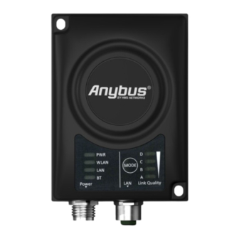
® ™ LED Indicators Anybus Wireless Bridge II Serial 7. LED Indicators Status Indicators Figure 9. Status LED indicators LED Indication Description No power Green Normal operation WLAN WLAN disabled or no power Blue, blinking Access Point: No clients, awaiting connections Blue Access Point: Connected to at least one Client Client: Connected to Access Point... - Page 28 ® ™ Anybus Wireless Bridge II Serial Link Quality/Mode Indicators Link Quality/Mode Indicators The Link Quality/Mode Indicators are used to indicate Bluetooth quality, selected Easy Config mode and update status in Recovery Mode. Figure 10. Link Quality/Mode indicators Table 5. RSSI (WLAN Client) / Link Quality (Bluetooth PANU) Description LED is off LED is off...
-
Page 29: Technical Specifications
® ™ Technical Specifications Anybus Wireless Bridge II Serial 8. Technical Specifications Order Code AWB3005 AWB3015 Serial interface Serial: RS232/RS422/RS485 Baud rate: 2400 - 921600 bit/s Data bits 5-8, stop bits 1-2, parity None, Odd, Even. Transparent serial protocol transfer including support for Modbus-RTU and Modbus-TCP to Modbus-RTU transparent routing. - Page 30 ® ™ Anybus Wireless Bridge II Serial Technical Specifications Order Code AWB3005 AWB3015 Power consumption 0.7 W idle, 1.7 W max (54mA@24VDC with Wireless LAN and 36mA@24VDC with Bluetooth) Enclosure material Plastic PC/ABS (Bayblend FR3010) Mechanical rating IP65 Mounting Two screws (Ø 4 mm) on flat surface. DIN rail mount option available (optional accessory). Max range 400 meters Antennas...
Need help?
Do you have a question about the Anybus Wireless Bridge II Serial AWB3005 and is the answer not in the manual?
Questions and answers