
Related Manuals for HMS Networks Anybus North ABC3213-A


Summary of Contents for HMS Networks Anybus North ABC3213-A
- Page 1 ENGLISH ® ™ Anybus Communicator - PROFINET to Modbus TCP Client USER MANUAL SCM-1202-228 Version 1.0 Publication date 2024-03-27...
- Page 2 The information in this document shall therefore not be construed as a commitment on the part of HMS Networks and is subject to change without notice. HMS Networks makes no commitment to update or keep current the information in this document.
-
Page 3: Table Of Contents
® ™ Anybus Communicator - PROFINET to Modbus TCP Client Table of Contents 1. Preface ..........................1 1.1. About This Document ......................1 1.2. Document Conventions ..................... 1 1.3. Trademarks ........................2 2. Safety ............................ 3 2.1. Intended Use ........................3 2.2. - Page 4 ® ™ Anybus Communicator - PROFINET to Modbus TCP Client 8.1. Connect the Communicator ....................34 8.2. Access the Built-In Web Interface from HMS IPconfig ............. 35 8.3. Access the Built-In Web Interface from a Web Browser ............37 8.4. Communicator Built-In Web Interface Overview ..............38 8.5.
- Page 5 ® ™ Anybus Communicator - PROFINET to Modbus TCP Client 11.5.3. Firmware File Validation ..................77 11.5.4. Update Firmware ....................78 11.6. Change Language ......................79 12. Troubleshooting ........................80 12.1. Diagnostics ........................80 12.1.1. I/O Data ....................... 80 12.1.2. Event Log ......................81 12.1.3.
- Page 6 This page is intentionally left blank.
-
Page 7: Preface
® ™ Preface Anybus Communicator - PROFINET to Modbus TCP Client 1. Preface 1.1. About This Document ® ™ This document describes how to install and configure Anybus Communicator For additional documentation and software downloads, FAQs, troubleshooting guides and technical support, please visit www.anybus.com/support. -
Page 8: Information Symbols
Additional information which may facilitate installation and/or operation. Helpful advice and suggestions. 1.3. Trademarks ® Anybus is a registered trademark of HMS Networks. All other trademarks are the property of their respective holders. Page 2 of 90 SCM-1202-228 Version 1.0... -
Page 9: Safety
® ™ Safety Anybus Communicator - PROFINET to Modbus TCP Client 2. Safety 2.1. Intended Use The intended use of this equipment is as a communication interface and gateway. The equipment receives and transmits data on various physical layers and connection types. If this equipment is used in a manner not specified by the manufacturer, the protection provided by the equipment may be impaired. -
Page 10: Cybersecurity
You find our Safety Advisories at www.hms-networks.com/cybersecurity/security-advisories. 3.3. How to Report a Vulnerability HMS Networks place the utmost importance on the security of our products and systems, however, despite all the measures we take, it cannot be excluded that vulnerabilities persist. -
Page 11: Product Cybersecurity Context
• Secure Boot: Security standard used to ensure that the Communicator boots using only software that is trusted by HMS Networks. • Signed firmware: HMS Networks delivers digitally signed firmware. Before the firmware file is imported into the Communicator, the firmware upgrade function performs a validation of the file, to ensure that is authentic. -
Page 12: Purdue Model
® ™ Anybus Communicator - PROFINET to Modbus TCP Client Product Cybersecurity Context 3.4.2. Purdue Model The Communicator is intended to be part of the process control network in Level 1 (E), to enable communication between PLCs or between a PLC and peripheral devices. Figure 1. -
Page 13: Preparation
® ™ Preparation Anybus Communicator - PROFINET to Modbus TCP Client 4. Preparation 4.1. Support and Resources For additional documentation and software downloads, FAQs, troubleshooting guides and technical support, please visit www.anybus.com/support. Have the product article number available, to search for the product specific support web page. You find the product article number on the product cover. -
Page 14: Hms Software Applications
® ™ Anybus Communicator - PROFINET to Modbus TCP Client HMS Software Applications 4.5. HMS Software Applications Download the software installation files and user documentation from www.anybus.com/support. HMS IPconfig Use the software application HMS IPconfig and scan your network to discover and change the Communicator IP address and to access the Communicator built-in web interface. -
Page 15: About Anybus Communicator
® ™ About Anybus Communicator Anybus Communicator - PROFINET to Modbus TCP Client 5. About Anybus Communicator 5.1. Modbus TCP Client Communication 5.1.1. Modbus TCP Client Building Blocks The following building blocks are used to describe the subnetwork communication. Server Figure 2. - Page 16 ® ™ Anybus Communicator - PROFINET to Modbus TCP Client Modbus TCP Client Communication Servers and Transactions Figure 3. Server with Transactions Transactions are based on standard Modbus transactions and define the data to be sent or received. See also (page 44).
-
Page 17: How The Communication Works
® ™ How the Communication Works Anybus Communicator - PROFINET to Modbus TCP Client 5.2. How the Communication Works The Communicator enables communication, data exchange, between one or more server devices connected to a subnetwork and a client device connected to a high level network. Figure 4. - Page 18 ® ™ Anybus Communicator - PROFINET to Modbus TCP Client How the Communication Works Transfer Process Data Figure 6. Process data traffic from client to servers Transfer process data from the high level network client device and make it available on the server interface and for the subnetwork nodes included in the configuration.
-
Page 19: How The Data Exchange Works
® ™ How the Data Exchange Works Anybus Communicator - PROFINET to Modbus TCP Client 5.3. How the Data Exchange Works Figure 7. The Communicator internal memory areas The data exchanged between the Communicator and the Modbus TCP subnetwork subnetwork and the high level network resides in the Communicator internal memory buffer. -
Page 20: Installation
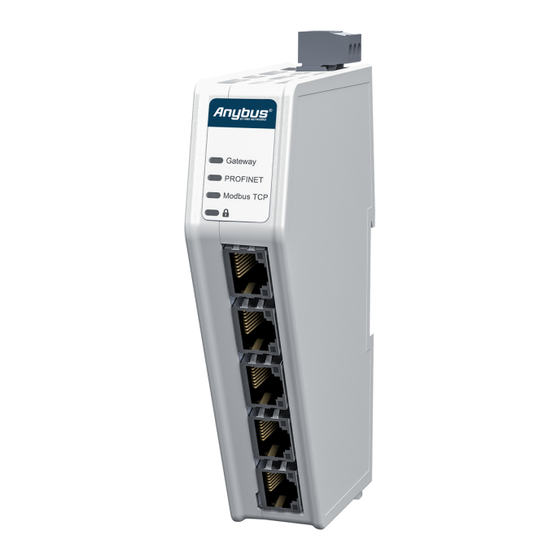
® ™ Anybus Communicator - PROFINET to Modbus TCP Client Installation 6. Installation 6.1. External Parts Figure 8. External parts Power connector PROFINET (X2.1) port Security switch Label with LED designation PROFINET (X2.2) port Factory reset button Status LEDs Modbus TCP Client (X3.1) port M. -
Page 21: Connector Port Guide
® ™ Connector Port Guide Anybus Communicator - PROFINET to Modbus TCP Client 6.2. Connector Port Guide This topic applies to different product variants for different networks. Figure 9. Communicator connector ports Position Port Number Connector Type Port Usage Ethernet Configuration port X2.1 Ethernet... -
Page 22: Label The Communicator With Network Stickers
® ™ Anybus Communicator - PROFINET to Modbus TCP Client Label the Communicator with Network Stickers 6.3. Label the Communicator with Network Stickers This topic applies to the Communicator Common Ethernet product variant. If you update the pre-configured firmware, you can use the included stickers to relabel the laser engraved marking next to the network LED indicators and connectors. -
Page 23: Din Rail Mounting
® ™ DIN Rail Mounting Anybus Communicator - PROFINET to Modbus TCP Client 6.4. DIN Rail Mounting IMPORTANT The equipment must be electrically grounded through the DIN rail for EMC compliance. Make sure that the equipment is correctly mounted on the rail and that the rail is properly grounded. IMPORTANT To physically secure networks and equipment and to prevent unauthorized access, it is recommended to install the equipment in a locked environment. -
Page 24: Connect To Modbus Tcp Client Network
® ™ Anybus Communicator - PROFINET to Modbus TCP Client Connect to Modbus TCP Client Network 6.5. Connect to Modbus TCP Client Network Figure 12. Connect to Modbus TCP Client network Procedure Connect the Communicator to your Modbus TCP Client network. Ethernet RJ45 Connector Pinout Ethernet RJ45 Connector Description... -
Page 25: Connect To Profinet Network
® ™ Connect to PROFINET Network Anybus Communicator - PROFINET to Modbus TCP Client 6.6. Connect to PROFINET Network Figure 13. Connect to PROFINET network Procedure Connect the Communicator to your PROFINET network. Ethernet RJ45 Connector Pinout Ethernet RJ45 Connector Description Not used Not used... -
Page 26: Connect To Power
® ™ Anybus Communicator - PROFINET to Modbus TCP Client Connect to Power 6.7. Connect to Power CAUTION Ensure that the power supply is turned off before connecting it to the equipment. IMPORTANT Using the wrong type of power supply can damage the equipment. Ensure that the power supply is connected properly and of the recommended type. -
Page 27: Security Switch
® ™ Security Switch Anybus Communicator - PROFINET to Modbus TCP Client 6.8. Security Switch IMPORTANT After completing the configuration of the Communicator, lock the security switch to prevent unauthorized access to the Communicator built-in web interface. When the security switch is in its locked position, the Communicator built-in web interface cannot be accessed, and the Communicator cannot be configured using the built-in web interface. - Page 28 ® ™ Anybus Communicator - PROFINET to Modbus TCP Client Security Switch Security Switch Status LED Figure 16. Security switch locked status LED When the security switch is in its: • locked position, the security switch status LED turn solid green. •...
-
Page 29: Lock The Cables
® ™ Lock the Cables Anybus Communicator - PROFINET to Modbus TCP Client 6.9. Lock the Cables Figure 17. Lock the cables To strain relieve the cables, place a cable tie in the holder and lock the cables. SCM-1202-228 Version 1.0 Page 23 of 90... -
Page 30: Din Rail Demount
® ™ Anybus Communicator - PROFINET to Modbus TCP Client DIN Rail Demount 6.10. DIN Rail Demount Before You Begin IMPORTANT Be careful when removing the Communicator from the DIN-rail. If not removed properly, the DIN rail locking mechanism and the product cover can break. Have a flat-blade screwdriver, size 5.5 mm, available. - Page 31 ® ™ DIN Rail Demount Anybus Communicator - PROFINET to Modbus TCP Client Hold the screwdriver in the DIN rail locking mechanism while you unhook the Communicator from the DIN rail. Figure 19. Unhook the Communicator SCM-1202-228 Version 1.0 Page 25 of 90...
-
Page 32: Configuration Quick Guide
® ™ Anybus Communicator - PROFINET to Modbus TCP Client Configuration Quick Guide 7. Configuration Quick Guide This section is intended to give you a brief overview of the tasks you need to perform to configure the Communicator. For detailed information, please refer to Communicator Configuration (page 34) 7.1. - Page 33 ® ™ Prepare Configuration Anybus Communicator - PROFINET to Modbus TCP Client Connect to PC and power Connect an Ethernet cable between the Communicator configuration port and your PC. Connect the Communicator to a power supply. Find the Communicator on your PC The Communicator default IP address is 192.168.0.10.
- Page 34 ® ™ Anybus Communicator - PROFINET to Modbus TCP Client Prepare Configuration Access the Communicator built-in web interface Open the Communicator built-in web interface in HMS IPconfig or enter the Communicator IP address in your web browser. The Communicator built-in web interface overview page opens in your browser. Page 28 of 90 SCM-1202-228 Version 1.0...
-
Page 35: Setup New Configuration
® ™ Setup New Configuration Anybus Communicator - PROFINET to Modbus TCP Client 7.2. Setup New Configuration Follow these steps to setup a new Communicator configuration. Subnetwork configuration On the Communication page: Enable DHCP or configure the IP settings manually. Add Servers On the Servers page: Add a server and configure the server Properties. - Page 36 ® ™ Anybus Communicator - PROFINET to Modbus TCP Client Setup New Configuration High level network configuration On the PROFINET page: Enable DHCP server or choose to set a specific IP address. I/O Configuration The transaction(s) for each server is automatically mapped to the Communicator internal memory area. On the I/O configuration page, view the mapping relation between the server connections and the layout on the process data area.
-
Page 37: Plc Configuration
® ™ PLC Configuration Anybus Communicator - PROFINET to Modbus TCP Client 7.3. PLC Configuration In the PLC program: Import product file Option if the PLC program requires an GSDML (Generic Station Description Markup Language) file. Import the GSDML file into your PLC project. Configure the communication Configure the PLC to communicate with the Communicator according to the I/O data map created in the Communicator. -
Page 38: Verify Operation
® ™ Anybus Communicator - PROFINET to Modbus TCP Client Verify Operation 7.4. Verify Operation Apply the configuration When you have completed and verified the configuration, click Apply for the settings to take effect. Verify status and LED indications On the Home page: Monitor the Communicator, network and server status. - Page 39 ® ™ Verify Operation Anybus Communicator - PROFINET to Modbus TCP Client Verify and monitor communication In Diagnostics, use the: • I/O data page to monitor how the data flow between the Modbus TCP Client side and the PROFINET side, including any configured endian conversions.
-
Page 40: Communicator Configuration
® ™ Anybus Communicator - PROFINET to Modbus TCP Client Communicator Configuration 8. Communicator Configuration 8.1. Connect the Communicator Procedure Connect to Modbus TCP Client network and PROFINET network Connect the Communicator to the high level network. Connect the Communicator to the subnetwork. Connect to PC and Power Connect an Ethernet cable between the Communicator and your PC. -
Page 41: Access The Built-In Web Interface From Hms Ipconfig
® ™ Access the Built-In Web Interface from HMS IPconfig Anybus Communicator - PROFINET to Modbus TCP Client 8.2. Access the Built-In Web Interface from HMS IPconfig Before You Begin Download the software application HMS IPconfig installation files and user documentation from www.anybus.com/support. - Page 42 ® ™ Anybus Communicator - PROFINET to Modbus TCP Client Access the Built-In Web Interface from HMS IPconfig Change the Communicator configuration port IP address to one within the same IP address range as your To open the Open web page built-in web interface, click Communicator. Result You are redirected to the Communicator built-in web interface Home page.
-
Page 43: Access The Built-In Web Interface From A Web Browser
® ™ Access the Built-In Web Interface from a Web Browser Anybus Communicator - PROFINET to Modbus TCP Client 8.3. Access the Built-In Web Interface from a Web Browser Before You Begin NOTE The Communicator configuration port default IP address is 192.168.0.10. NOTE To access the Communicator built-in web interface, ensure that Port 80 TCP is open in your Firewall. -
Page 44: Communicator Built-In Web Interface Overview
® ™ Anybus Communicator - PROFINET to Modbus TCP Client Communicator Built-In Web Interface Overview 8.4. Communicator Built-In Web Interface Overview Use the Communicator built-in web interface to configure, maintain and troubleshoot the Communicator. Figure 20. The Communicator built-in web interface Home page Menu item Description Home... -
Page 45: Modbus Tcp Client Communication Settings
® ™ Modbus TCP Client Communication Settings Anybus Communicator - PROFINET to Modbus TCP Client 8.5. Modbus TCP Client Communication Settings 8.5.1. To Use DHCP Server Figure 21. IP Settings, DHCP enabled By default, DHCP is disabled. To enable DHCP, select the DHCP enabled checkbox. The IP settings will be provided by the high level network DHCP server. -
Page 46: To Configure Ip Settings Manually
® ™ Anybus Communicator - PROFINET to Modbus TCP Client Modbus TCP Client Communication Settings 8.5.2. To Configure IP Settings Manually Figure 22. Modbus TCP Client IP Settings, DCHP disabled Ensure that the DHCP enabled checkbox is deselected. Configure the IP settings. Setting Description IP address... -
Page 47: Servers
® ™ Servers Anybus Communicator - PROFINET to Modbus TCP Client 8.6. Servers 8.6.1. Add Server Before You Begin NOTE The maximum number of servers that can be added is 64. Procedure In the web-interface left sidebar menu, click Servers. Click Add. -
Page 48: Server Properties
® ™ Anybus Communicator - PROFINET to Modbus TCP Client Servers 8.6.2. Server Properties Procedure Figure 25. Servers page, Properties In the server list, select a server to configure. Configure the Properties. Setting Value Description Name Server [n] The default name is Server, followed by an incremental number suffix. IP address Default 0.0.0.0 The server IP address in IPv4 dot-decimal notation... -
Page 49: Add Transactions
® ™ Servers Anybus Communicator - PROFINET to Modbus TCP Client 8.6.3. Add Transactions Before You Begin NOTE The transactions are executed in the order they appear in the Server Transaction list. NOTE One transaction is performed at a time per connection. NOTE You can add a maximum of 152 transaction units distributed among the servers. -
Page 50: Modbus Transactions
® ™ Anybus Communicator - PROFINET to Modbus TCP Client Servers 8.6.4. Modbus Transactions Reference: MODBUS Application Protocol Specification V1.1b3, April 26 2012 For more information refer to the Modbus organization website. Transaction Area Function Code Description Read Coils Coils 0x01 Read from 1 to 2000 contiguous status of coils in a remote device. -
Page 51: Transaction Properties
® ™ Servers Anybus Communicator - PROFINET to Modbus TCP Client 8.6.5. Transaction Properties Before You Begin For Modbus transaction reference guide, refer to Modbus Transactions (page 44). Procedure Figure 27. Transaction properties In the Modbus TCP Client server list, select a server to configure. In the Transactions list, select a transaction to configure. - Page 52 ® ™ Anybus Communicator - PROFINET to Modbus TCP Client Servers Setting Value Setting for Modbus Transaction Description Quantity to write Write Multiple Registers (16), 1 to 123 Specifies the quantity of registers to follow in the write data field. Read Write Multiple Registers (23), 1 to 121 Quantity of bits Read Coils (1), 1 to 2000...
-
Page 53: Duplicate Transaction
® ™ Servers Anybus Communicator - PROFINET to Modbus TCP Client 8.6.6. Duplicate Transaction When you duplicate a transaction, all settings are preserved. Figure 28. Duplicate transaction To duplicate, select the checkbox in front of each transaction you want to duplicate and click the Duplicate icon. The duplicated transaction(s) is added at the bottom of the transactions list. -
Page 54: Profinet Settings
® ™ Anybus Communicator - PROFINET to Modbus TCP Client PROFINET Settings 8.7. PROFINET Settings 8.7.1. To Use DHCP Server Figure 30. IP Settings, DHCP enabled By default, DHCP is disabled. To enable DHCP, select the DHCP enabled checkbox. The IP settings will be provided by the high level network DHCP server. -
Page 55: To Configure Ip Settings Manually
® ™ PROFINET Settings Anybus Communicator - PROFINET to Modbus TCP Client 8.7.2. To Configure IP Settings Manually Figure 31. PROFINET IP Settings, DCHP disabled Deselect the DHCP enabled checkbox. Configure the IP settings. Setting Description IP address The PROFINET network IP address in IPv4 dot-decimal notation Subnet mask The PROFINET network Subnet mask in IPv4 dot-decimal notation. -
Page 56: Profinet Station Name Settings
® ™ Anybus Communicator - PROFINET to Modbus TCP Client PROFINET Settings 8.7.4. PROFINET Station Name Settings Figure 33. PROFINET page, Station name A PROFINET device is identified by its Station name in the PROFINET network. Enter a Station name for the Communicator. •... -
Page 57: Profinet Advanced Settings
® ™ PROFINET Advanced Settings Anybus Communicator - PROFINET to Modbus TCP Client 8.8. PROFINET Advanced Settings NOTE The Advanced settings is used to makes the Communicator compatible with the Anybus X-gateway. 8.8.1. Legacy Mode Advanced settings option for PROFIBUS. Before You Begin If you already have an Anybus X-gateway GSDML (Generic Station Description Markup Language) file installed in your PLC, legacy mode allows you to continue using the settings from the GSDML file for the new Communicator. -
Page 58: I/O Configuration
® ™ Anybus Communicator - PROFINET to Modbus TCP Client I/O Configuration 8.9. I/O Configuration Figure 35. I/O configuration page On the I/O configuration page the data communication between the Modbus TCP server devices and the PROFINET network is mapped. The allocated I/O area is auto generated based on the Modbus TCP server devices network server(s) configuration and how the settings on the PROFINET page are configured. -
Page 59: Map Area Object Order
® ™ I/O Configuration Anybus Communicator - PROFINET to Modbus TCP Client 8.9.1. Map Area Object Order To change the order of the objects in a map area, drag and drop the desired transaction to a new location. Objects can not share the same I/O area. Figure 36. -
Page 60: Convert Between Big-Endian And Little-Endian
® ™ Anybus Communicator - PROFINET to Modbus TCP Client I/O Configuration 8.9.3. Convert Between Big-Endian and Little-Endian To convert between big-endian and little-endian you must reverse the byte order. Figure 37. I/O configuration page, Endian swap To reverse the byte order: In the web-interface left sidebar menu, click I/O configuration. -
Page 61: Live List
® ™ I/O Configuration Anybus Communicator - PROFINET to Modbus TCP Client 8.9.4. Live List Figure 38. I/O configuration page, Live list enabled By default, Live list is disabled. About the Live List • When Live list is enabled, the first four bytes of process data on the PROFINET network contain the live list. •... - Page 62 ® ™ Anybus Communicator - PROFINET to Modbus TCP Client I/O Configuration Live List Size and Transaction Order Figure 39. Live list properties and Transaction order The default Live list size is 4 bytes. The size of the live list can be configured within the range of 1 to 19 bytes. In the Transaction order list, you can view the order in which the transactions are executed.
-
Page 63: Data Exchange Control
® ™ I/O Configuration Anybus Communicator - PROFINET to Modbus TCP Client 8.9.5. Data Exchange Control Figure 40. I/O configuration, Data exchange control enabled By default Data exchange control is disabled. When Data exchange control is enabled, the first four bytes of process data on the PROFINET network contain the data exchange control. - Page 64 ® ™ Anybus Communicator - PROFINET to Modbus TCP Client I/O Configuration Data Exchange Control Size and Transaction Order Figure 41. Data exchange control properties and Transaction order The default Data exchange control size is 4 bytes. The size of the data exchange control can be configured within the range of 1 to 19 bytes. In the Transaction order list, you can view the order in which the transactions are executed.
-
Page 65: Configuration Notes
® ™ Configuration Notes Anybus Communicator - PROFINET to Modbus TCP Client 8.10. Configuration Notes You can add notes to describe the Communicator configuration. 8.10.1. Add Configuration Note Procedure To open the Configuration Notes window, click on the comments icon Figure 42. - Page 66 ® ™ Anybus Communicator - PROFINET to Modbus TCP Client Configuration Notes Write your configuration note and click accept Figure 44. Write a configuration note The configuration note is added to the list. To close the window, click close To save the configuration note, click Apply in the web-interface header, and follow the instructions. Page 60 of 90 SCM-1202-228 Version 1.0...
-
Page 67: View And Edit Configuration Notes
® ™ Configuration Notes Anybus Communicator - PROFINET to Modbus TCP Client 8.10.2. View and Edit Configuration Notes To view and/or edit a note, click on the comments icon Figure 45. Example: The comment icon indicates that there are three added notes The configuration notes are listed in the Configuration Note window. -
Page 68: Apply Configuration
® ™ Anybus Communicator - PROFINET to Modbus TCP Client Apply Configuration 8.11. Apply Configuration Before You Begin NOTE When you apply the configuration, any existing configuration is overwritten. Figure 47. Procedure To make the settings take effect, download the configuration to the Communicator: In the web-interface header, click Apply To confirm download, click Apply. -
Page 69: To Use An Existing Configuration
® ™ To Use an Existing Configuration Anybus Communicator - PROFINET to Modbus TCP Client 8.12. To Use an Existing Configuration When you have configured a Communicator and want to use the same settings to configure additional Communicator, do the following. Procedure Figure 48. -
Page 70: To Use A Legacy Modbus Tcp Client Configuration
® ™ Anybus Communicator - PROFINET to Modbus TCP Client To Use a Legacy Modbus TCP Client Configuration 8.13. To Use a Legacy Modbus TCP Client Configuration Before You Begin The intended use of the X-gateway configuration import is to get a new Communicator unit up and running quickly and then complete the configuration in the Communicator built-in web interface. - Page 71 ® ™ To Use a Legacy Modbus TCP Client Configuration Anybus Communicator - PROFINET to Modbus TCP Client To import the configuration, click Import. Figure 50. Example, selected .cfg file Option when the X-gateway configuration file is protected with a username and password. Select the Authentication details checkbox and enter the username and password.
- Page 72 ® ™ Anybus Communicator - PROFINET to Modbus TCP Client To Use a Legacy Modbus TCP Client Configuration Result The X-gateway Modbus TCP Client configuration settings are imported. A window with messages about the imported configuration appears. In the list you can view the settings that are supported or adjusted to work with Communicator and which settings that are not supported and must be set manually in the Communicator built-in interface.
-
Page 73: Plc Configuration
® ™ PLC Configuration Anybus Communicator - PROFINET to Modbus TCP Client 9. PLC Configuration 9.1. PLC Device Security IMPORTANT It is important to maintain the cybersecurity of the Communicator. Before connecting the Communicator to a PLC, ensure the PLC is configured and installed in accordance with the PLC supplier hardening guidelines. -
Page 74: Verify Operation
® ™ Anybus Communicator - PROFINET to Modbus TCP Client Verify Operation 10. Verify Operation 10.1. Communicator Status Monitor On the Home page, you can get a quick overview of the network and the Communicator operating status. Figure 54. Home page Gateway Status Overview the Communicator LED indications remotely. -
Page 75: Status Symbols
® ™ Communicator Status Monitor Anybus Communicator - PROFINET to Modbus TCP Client Status Symbols Symbol Description Internal error has occurred, and operation cannot be guaranteed. Out of Specification. Check Function: • Initial state where non network components are started and configured. •... -
Page 76: Communicator Led Indicators
® ™ Anybus Communicator - PROFINET to Modbus TCP Client Communicator LED Indicators 10.2. Communicator LED Indicators This topic applies to different product variants for different networks. NOTE Before you can verify operation, you must configure the Communicator. Figure 55. Gateway status (A), Network connection (B)/(C) and Security switch (D) LED A - Gateway status Operation Status Description... -
Page 77: Ethernet Led Indicators
® ™ Ethernet LED Indicators Anybus Communicator - PROFINET to Modbus TCP Client Connection to subnetwork Modbus TCP client device • LED C for PROFINET network • LED B for EtherNet/IP, PROFIBUS, and EtherCAT networks Operation status Description No IP address. Red, flashing At least one connection error or timeout. -
Page 78: Maintenance
® ™ Anybus Communicator - PROFINET to Modbus TCP Client Maintenance 11. Maintenance 11.1. Action on Fatal Error Figure 57. System page, Action on fatal error menu A fatal error causes the Communicator firmware application to crash in an uncontrolled manner. You can configure how the Communicator should behave if a fatal error occurs. -
Page 79: Configuration Port Ip Settings
® ™ Configuration Port IP Settings Anybus Communicator - PROFINET to Modbus TCP Client 11.2. Configuration Port IP Settings On the System page you can change the IP address of the Communicator configuration port. Figure 58. System page, Configuration port settings Default Configuration Port IP settings Setting Default value... -
Page 80: Configuration File Handling
® ™ Anybus Communicator - PROFINET to Modbus TCP Client Configuration File Handling 11.3. Configuration File Handling 11.3.1. Export Configuration You can export the current configuration, to import and use the same settings to configure additional Communicator. Figure 59. Files & firmware page To export a configuration file: In Files &... -
Page 81: Import Configuration
® ™ Configuration File Handling Anybus Communicator - PROFINET to Modbus TCP Client 11.3.2. Import Configuration To easily configure multiple Communicator with the same settings, you can import a configuration file. Before You Begin NOTE Importing a configuration replaces the current applied configuration. The supported file format is .conf. -
Page 82: Clear And Revert Configuration
® ™ Anybus Communicator - PROFINET to Modbus TCP Client Clear and Revert Configuration 11.4. Clear and Revert Configuration You can restore all settings in a configuration to the default settings. Procedure Figure 61. Files & firmware page To Clear the Configuration When you want to clear a configuration and return to the default settings. -
Page 83: Firmware Management
® ™ Firmware Management Anybus Communicator - PROFINET to Modbus TCP Client 11.5. Firmware Management 11.5.1. View the Firmware Version On the Support page, you can view the current applied firmware version. Figure 62. Support page, Product information example 11.5.2. Firmware and Configuration Compatibility Compatibility after firmware upgrade Current configuration is still compatible after upgrading the firmware. -
Page 84: Update Firmware
® ™ Anybus Communicator - PROFINET to Modbus TCP Client Firmware Management 11.5.4. Update Firmware Before You Begin IMPORTANT To eliminate the risk of interference with plant operation, firmware update is only available when the Communicator is disconnected from the OT networks. Ensure to disconnect the Communicator from the OT networks. -
Page 85: Change Language
® ™ Change Language Anybus Communicator - PROFINET to Modbus TCP Client 11.6. Change Language Default language is English. To change the language of the Communicator built-in web interface: In the Communicator built-in web-interface header, click the Language icon Figure 64. Language menu Select a new language from the list. -
Page 86: Troubleshooting
® ™ Anybus Communicator - PROFINET to Modbus TCP Client Troubleshooting 12. Troubleshooting 12.1. Diagnostics 12.1.1. I/O Data On the Diagnostics, I/O data page you can monitor how the data flow between the Modbus TCP Client side and the PROFINET side, including any configured endian conversions. Figure 66. -
Page 87: Event Log
® ™ Diagnostics Anybus Communicator - PROFINET to Modbus TCP Client 12.1.2. Event Log Figure 67. Event log page example How To Analyze the Information The log follows the FIFO principle, first in and first out. The oldest (first) value is processed first. Time (d:hh:mm:ss.ms) The date and time when the event occurred. -
Page 88: Led Status
® ™ Anybus Communicator - PROFINET to Modbus TCP Client Diagnostics 12.1.3. LED Status On the Home page, you can remotely monitor the Communicator LED status. Figure 68. Home page For information about the LED indication, see Communicator LED Indicators (page 70). -
Page 89: Reset To Factory Settings
® ™ Reset to Factory Settings Anybus Communicator - PROFINET to Modbus TCP Client 12.2. Reset to Factory Settings Before You Begin Factory reset will reset any on site made configuration changes and set the Communicator to the same state as leaving HMS production. - Page 90 ® ™ Anybus Communicator - PROFINET to Modbus TCP Client Reset to Factory Settings While holding the reset button, reconnect the Communicator to power. Figure 71. Hold Reset button and reconnect power Release the reset button. The Communicator enters exception state. Reboot the Communicator.
- Page 91 ® ™ Reset to Factory Settings Anybus Communicator - PROFINET to Modbus TCP Client Navigate to the Files & firmware page and click Revert. Figure 72. Files & firmware, Revert SCM-1202-228 Version 1.0 Page 85 of 90...
-
Page 92: Firmware Upgrade Error Management
® ™ Anybus Communicator - PROFINET to Modbus TCP Client Firmware Upgrade Error Management 12.3. Firmware Upgrade Error Management Before You Begin If the firmware update process is interrupted or if the power is lost during the update process, the Communicator goes into fallback mode. - Page 93 ® ™ Firmware Upgrade Error Management Anybus Communicator - PROFINET to Modbus TCP Client Leave the Communicator for 10 minutes. The Gateway status led indicator flashes red and green until the firmware upgrade is completed. Figure 75. Firmware upgrade LED indication Result The Communicator recover and return to normal operation.
-
Page 94: Support
® ™ Anybus Communicator - PROFINET to Modbus TCP Client Support 12.4. Support 12.4.1. Support Package Figure 77. Support page example Before you create a ticket for technical support, generate a support package. The support package contains information about what has occurred and will help the Anybus technical support team resolve the support case as quickly and efficiently as possible. -
Page 95: End Product Life Cycle
® ™ End Product Life Cycle Anybus Communicator - PROFINET to Modbus TCP Client 13. End Product Life Cycle 13.1. Secure Data Disposal IMPORTANT To avoid exposure of sensitive data, always perform a factory reset before decommissioning the equipment. Factory reset will reset any on site made configuration changes and set the Communicator to the same state as leaving HMS production. -
Page 96: Technical Data
® ™ Anybus Communicator - PROFINET to Modbus TCP Client Technical Data 14. Technical Data For complete technical specifications and regulatory compliance information, please visit www.anybus.com. 14.1. Technical Specification Article identification ABC3213 Configuration connector RJ45 Communication connector RJ45 x 2 Modbus TCP Client connector RJ45 x 2 Power connector...
Need help?
Do you have a question about the Anybus North ABC3213-A and is the answer not in the manual?
Questions and answers