Table of Contents
Advertisement
Quick Links
Advertisement
Table of Contents

Related Manuals for HMS Networks Anybus Wireless Bolt LTE


Summary of Contents for HMS Networks Anybus Wireless Bolt LTE
- Page 1 ® ™ Anybus Wireless Bolt LTE STARTUP GUIDE SP2868 1.1 en-US ENGLISH...
-
Page 2: Important User Information
HMS Networks reserves the right to modify its products in line with its policy of continuous product development. The information in this document shall therefore not be construed as a commitment on the part of HMS Networks and is subject to change without notice. -
Page 3: About This Document
Preface 3 (20) Preface About This Document This manual describes how to install and configure Anybus Wireless Bolt LTE. For additional documentation and software downloads, FAQs, troubleshooting guides and technical support, please visit www.anybus.com/support. ® ™ SP2868 1.1 en-US Anybus... -
Page 4: Document Conventions
Preface 4 (20) Document Conventions Numbered lists indicate tasks that should be carried out in sequence: First do this Then do this Bulleted lists are used for: • Tasks that can be carried out in any order • Itemized information ►... -
Page 5: General Safety Instructions
Safety 5 (20) Safety General Safety Instructions Caution This equipment emits RF energy in the ISM (Industrial, Scientific, Medical) band. Make sure that all medical devices used in proximity to this equipment meet appropriate susceptibility specifications for this type of RF energy. -
Page 6: Installation
Installation 6 (20) Installation Installing SIM Card Supported SIM card types are Nano SIM for IoT and M2M, for data communication, as well as standard mobile phone Nano SIM. Fig. 1 To connect Wireless Bolt LTE to a cellular data network, install a cellular SIM card: Insert a SIM card into the Wireless Bolt LTE SIM card holder. -
Page 7: Mechanical Installation
Installation 7 (20) Mechanical Installation Placement • The device is intended to be mounted on top of a machine or cabinet through an M50 (50.5 mm) hole using the included sealing ring and nut. • The top mounting surface, in contact with the sealing, must be flat with a finish equivalent to Ra 3.2 or finer and cleaned and free from oils and greases. - Page 8 Installation 8 (20) Tightening torque: 5 Nm ±10 % Fig. 2 Installation drawing All measurements are in mm. ® ™ SP2868 1.1 en-US Anybus Wireless Bolt LTE Startup Guide...
- Page 9 Installation 9 (20) Connecting to Power Over Ethernet (PoE) Before You Begin Connecting the Wireless Bolt LTE to PoE and DC power simultaneously may result in a current loop that could damage both the power sources and the Wireless Bolt LTE. Ensure to use only one of the power connections at a time.
- Page 10 Installation 10 (20) Ethernet Connector, RJ45 PoE Data Positive power from alt. A PSE Negative power from alt. A PSE (with pin 6) Positive power from alt. B PSE Negative power from alt. A PSE (with pin 3) Negative power from alt. B PSE Functional Earth (FE), via 1 nF capacitor and 1 MΩ...
- Page 11 Installation 11 (20) When Wireless Bolt LTE is installed in an environment with a high level of electrical noise, use a power/Functional Earth (FE) cable with a maximum length of 3 meters. See also Technical Data, p. 18 regarding power supply requirements. Functional earth wire screw placement Fig.
- Page 12 Installation 12 (20) Procedure Connecting to power Fig. 5 Connect Wireless Bolt LTE Power connector to a power supply. Connect Wireless Bolt LTE Power connector to Functional Earth (FE). Power connector, 3-pin terminal block Function 11–33 VDC Functional Earth (FE) ®...
- Page 13 Installation 13 (20) Connecting to Ethernet Connect the Wireless Bolt LTE to Ethernet. Fig. 6 ® ™ SP2868 1.1 en-US Anybus Wireless Bolt LTE Startup Guide...
- Page 14 Configuration 14 (20) Configuration Wireless Bolt LTE Built-In Web Interface Fig. 7 Example, Wireless Bolt LTE built-in web interface The Wireless Bolt LTE built-in web interface is used to configure the Wireless Bolt LTE system settings. The System Overview page shows the current settings and network connection status.
- Page 15 Configuration 15 (20) Procedure Fig. 8 Connecting Wireless Bolt LTE to internet: Insert a cellular SIM card in the Wireless Bolt LTE SIM card holder. Ensure that the SIM card contact surface is facing towards the Ethernet port. Connect the Wireless Bolt LTE Ethernet port to your PC. Connect the Wireless Bolt LTE Power connector to a power supply.
- Page 16 Configuration 16 (20) Result Wireless Bolt LTE should now be connected to internet. Depending on the mobile network operator and network type, it can take up to 10 minutes the first time Wireless Bolt LTE is connecting to internet. Verify that Wireless Bolt LTE is connected to internet, by sending a ping to Google Public DNS.
- Page 17 Configuration 17 (20) Connecting Devices Fig. 10 Connecting a device to internet: Connect an Ethernet cable between Wireless Bolt LTE and the device. Verify that the device is connected to internet. ® ™ SP2868 1.1 en-US Anybus Wireless Bolt LTE Startup Guide...
-
Page 18: Technical Data
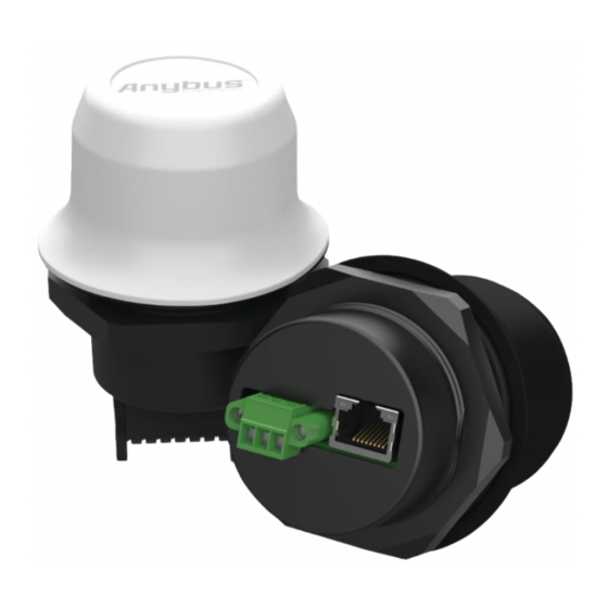
Technical Data 18 (20) Technical Data Technical Specifications EMEA: AWB1500 EMEA: AWB1501 Order code Americas: AWB1502 Americas: AWB1503 Color Black White top and black base Operating temperature Shadow: -40 to +65 °C Shadow: -40 to +65 °C Direct sunlight: -40 to +45 Direct sunlight: -40 to +65 °C °C... - Page 19 Technical Data 19 (20) EMEA: AWB1500 EMEA: AWB1501 Order code Americas: AWB1502 Americas: AWB1503 Cellular standards EMEA: LTE B1, B3, B7, B8, B20, B28. Fallback 3G and Americas: LTE B2, B4, B5, B12, B13, B14, B25, B26, B66. Fallback 3G. Maximum Data speeds Max download speed: 100 Mbit/s Max upload speed: 50 Mbit/s...
- Page 20 last page © 2021 HMS Industrial Networks Box 4126 300 04 Halmstad, Sweden info@hms.se SP2868 1.1 en-US / 2021-09-01 / 23260...
Need help?
Do you have a question about the Anybus Wireless Bolt LTE and is the answer not in the manual?
Questions and answers