Table of Contents
Advertisement
Quick Links
Advertisement
Table of Contents

Related Manuals for Thermo Scientific Apreo


Summary of Contents for Thermo Scientific Apreo
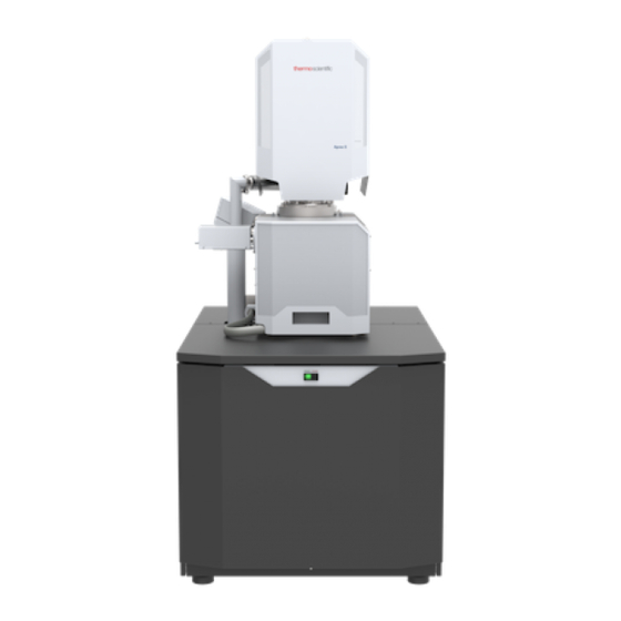
- Page 1 Apreo User Operation Manual Revision A Mar-2018...
- Page 2 Trademark Acknowledgments Microsoft® and Windows are registered trademarks of Microsoft Corporation. This manual was produced using FrameMaker™ document publishing software. FrameMaker™ and Adobe are registered trademarks of Adobe Systems Incorporated. Other product and company names mentioned herein may be trademarks of their respective owners. Copyright ©...
-
Page 3: Table Of Contents
Apreo User safety manual ........ - Page 4 Table of contents Entering commands ........3-52 Using mouse .
- Page 5 Table of contents Detection Principles..........5-20 Beam Deceleration module .
- Page 6 Table of contents CryoCleanerEC ........7-30 Parts and Accessories.
-
Page 7: Chapter 1 System Overview
System overview User manuals Apreo User safety manual The safety manual provides information for personal safety and maintenance procedures while operating this system. This manual is required reading for the end user. User operation manual The User Manual is delivered as an electronic PDF file only. However, it is possible to print parts of the manual if this is desired. -
Page 8: System Capabilities
System overview: System capabilities System capabilities The Apreo is a Scanning Electron Microscope (SEM) that produces enlarged images of a variety of specimens, achieving magnification over 100 000× and provides high resolution imaging in a digital format. The instrument provides optimum throughput, resolution and automation. - Page 9 HiVac mode. Stage The Apreo has a computer-controlled high-accuracy five-axis stage for small samples. It offers precision specimen computer controlled manipulation and automation of all axes for overall spatial orientation on highly repetitive or extremely irregular samples.
- Page 10 System overview: System capabilities Image viewing and capture Because the amplified detector signal is shown synchronously with the beam scanning, there is a relationship between brightness of an image point on the monitor screen and the signal detected at the corresponding point on the specimen.
-
Page 11: Chapter 2 System Control
Microscope console. Optionally it is possible to have a second LCD monitor with the Microscope computer or the Support computer, using the LCD monitor and the switch box with keyboard and mouse to switch between the two computers. Apreo standard layout scheme FIGURE 2-1: ... -
Page 12: Interface Elements
System control: Interface elements Interface elements Software The software control contains graphics applications within the Windows 7™ operating environment: • xT microscope Server: starts and stops basic microscope functions • Microscope Control (UI – User Interface): controls all system functions including imaging, image and movie gathering / manipulation / output, detection and analysis, scanning, magnification, stage navigation, chamber and column pressure, etc. -
Page 13: Mains Switchboard
System control: Interface elements External connectors panel The External connectors panel is located on the back of the microscope console. It is used to connect 3rd party equipment to the following connectors: CONTROL SIGNALS / E-BEAM SCAN INPUT / VIDEO These connectors are used for the connection of EDX, WDX and lithography systems, provided by 3rd party suppliers. - Page 14 To switch off the electrical power completely in case of emergency, follow this quick and safe procedure: 1. Push the red EMERGENCY OFF (EMO) button (option – see the Apreo User safety manual). If the button is not installed proceed as follows: 2.
-
Page 15: System States
System control: System states System states There are several system states: • Complete shutdown – for service and emergency reasons • Standby – for when the system will not be used for a longer period • Overnight – for when the system will not be used overnight •... -
Page 16: Overnight And Standby
System control: System states 9. Select the desired Vacuum module / Vacuum mode radio button and click on the Vacuum module / Pump Button. Wait for the Pumped status. 10. Click on the Column module / Beam On button to start the beam. - Page 17 System control: System states To bring the system back to operation, follow this procedure: C a u t i o n ! When the Standby state was just entered, wait a minimum of 10 seconds before starting the microscope operation again (by pressing the power button on the microscope front control panel)! 1.
-
Page 18: System Shutdown
System control: System states System shutdown In case of emergency, bring the system to the Complete shutdown state by following this procedure: 1. Click on the Column module / Beam On button to stop the accelerating voltage. A Column module / Source progress bar indicates the actual status;... -
Page 19: Vacuum System
Vacuum system Model difference There are the High Vacuum and Low Vacuum variations of the Apreo system. This manual describes the Low Vacuum model. For the High Vacuum model, some controls are missing and functionality is modified accordingly. The system has the these vacuum sections: •... -
Page 20: Vacuum Status
System control: Vacuum system Vacuum status The vacuum status controls are in the Vacuum module. The Pump button starts pumping the chamber for the operating pressure and the Vent button starts venting the chamber for a sample exchange. At the bottom right side of the status bar the actual vacuum status is represented by the colored icon, which may have three possible colors with the following meanings: •... -
Page 21: Vacuum Modes
System control: Vacuum system Vacuum modes The Vacuum module / High Vacuum or Low Vacuum radio buttons are used to select the instrument target operating mode when a Pump sequence is initiated. When changing the vacuum mode from one mode to another, a confirmation dialog appears. - Page 22 System control: Vacuum system loss in the gas. For EDX, samples are scanned at a 10 mm working distance, which is the stage eucentric position and the collection point of the EDX detector. The cone height is 5.5 mm and restricts the field of view. See Chapter 5 for the cone mounting procedure.
-
Page 23: Equipment
The accessibility / inaccessibility of detectors (black / gray label) depends on actual system conditions. Note For settings and handling of particular standard / optional detectors, see Chapters 5 and 7. Apreo detectors list Table 2-2: Detector name Vacuum mode Detected signal Note Everhart-Thornley... - Page 24 System control: Equipment Safety interlock message FIGURE 2-5: 2-14 User Manual C O N F I D E N T I A L – limited rights Feb 2018 Revision A...
-
Page 25: Stages And Accessories
System control: Equipment Stages and accessories The chamber is equipped with an 110 × 110 mm stage, that can be oriented with reference to five axes: X, Y, Z, Rotation and Tilt. All movements are motorized and software controlled (an integrated part of the Microscope Control software). - Page 26 System control: Equipment Stage movement limits The motorized movements of the stage can be operated under software control for more advanced location mapping. This includes Shift, Get, Track and Stage module functionality. A live image can be repositioned either by the stage movement or by the Beam Shift.
-
Page 27: Chapter 3 Software Control
Software control This chapter describes the functionality of each part of the user software interface within the Windows 7™ operating system: • xT microscope Server • Microscope Control (UI – User Interface) • User Management Software interface elements Icons Icons are small symbols indicating a specific software application. Double- click on an icon located on the desktop or within a folder to activate its program. -
Page 28: Command Buttons
Software control: Software interface elements Using the mouse Click on / right-click on / wheel-click on represents clicking with the left / right / wheel mouse button on an item throughout this manual. The click on & drag / right-click on & drag / wheel-click on & drag means holding the mouse button during a dragging action. -
Page 29: Adjusters
Software control: Software interface elements Adjusters Adjusters allow the user to change parameters (such as contrast, brightness, etc.) in a continuous way. Right-clicking on the adjuster shows a context menu with choices. Checking / not-checking the Slider Mode option switches between two possible ways of controlling the slider. -
Page 30: 2D Controls
Software control: Software interface elements 2D controls This control method is represented by an X-Y box. The position of the crosshair corresponds to the actual parameter value; its full range is represented by the perimeter of the box. Clicking on & dragging anywhere inside the box changes the active cursor to the 4-ended arrow and positions it at the screen point corresponding to the actual control value (minimum in the middle of the screen and maximum at the edges). -
Page 31: Xt Microscope Server
Software control: xT microscope Server xT microscope Server The xT microscope Server application starts and stops the software service controlling basic microscope functions as well as the user interface (UI) Microscope Control software. Start the xT microscope Server from the Windows Start menu or by double-clicking its icon. -
Page 32: Microscope Control
Software control: Microscope Control Microscope Control The Microscope Control application – simply the User Interface (UI) – is made up of several elements that compose the main window, showing status and control features within the Windows 7 operating system. Microscope Control window FIGURE 3-2: 4 - display 1 4 - display 2... - Page 33 Software control: Microscope Control Toolbar customization Selecting the Toolbar tab adds a red triangle to each toolbar item, that allows changing its size. By clicking & dragging any item, that item can be moved to a new position within the toolbar area; dragging it out of the toolbar area to the customization window eliminates it from the layout.
- Page 34 Software control: Microscope Control Keyboard (Shortcuts) customization It is possible to customize the factory shortcuts within the Kayboard tab. To change the factory settings, search for a desired functionality, enter a New Shortcut to the edit field, and click the Assign button. To revert to the factory settings, click the Default button.
-
Page 35: Menu Bar
Software control: Microscope Control Menu bar The pull-down menus are shown across the screen. The Menu Bar FIGURE 3-6: Expand pull-down menus from the menu bar by: • Clicking on the Menu title • Entering Alt + underscored keyboard letters •... - Page 36 Software control: Microscope Control Save All (Ctrl + Shift + S) opens a common dialog for saving images from each display, providing an opportunity to change the file names and locations. Record Movie (Ctrl + Shift + M) allows a user to make digital video files (AVI) for dynamic experiments.
- Page 37 • The 3rd party detector / video signal is indicated as “External”. Contact an Thermo Scientific service person about connection details. • The CCD camera reflects the inner space of the specimen chamber.
- Page 38 Software control: Microscope Control Full Frame (Ctrl + M) This is the default scanning mode. It is typical for navigation and imaging. Spot (Ctrl + K) When starting this mode, the actual beam position is represented by a green cross in all imaging displays. You can click on &...
- Page 39 Software control: Microscope Control Integrate Filter allows cumulative noise reduction by true integration over a specified number (2 or more) of frames. This process continues until the selected number of frames is reached. It then automatically pauses the imaging. This can be used as an alternative to slow scanning to obtain high quality images of slightly charging specimens. ...
- Page 40 Software control: Microscope Control Patterning menu opens the Patterning menu functions (see Chapter 5): Start / Pause / Resume Patterning in Display # (Pause button) starts / pauses patterning of the enabled pattern(s) in the active display. The menu item and the corresponding toolbar icon change according to the actual condition.
- Page 41 Software control: Microscope Control Stage menu opens the stage and sample navigation functions (see Chapter 5): Align Feature opens the procedure that helps set a stage position for any elongated feature (extending off the screen at the desired magnification). The procedure uses the stage rotation. Compucentric Rotation (F12) places a green circle in the active display.
- Page 42 Software control: Microscope Control Unlink Z to FWD This feature functions in the opposite way as the Link Z to FWD (see below). The Z coordinate value then represents the distance from the Z-axis home position (stage base). The dialog warns of the stage Z-axis positive move direction.
- Page 43 Software control: Microscope Control Tools menu opens the Tools menu functions: Auto Contrast Brightness (F9) activates the automatic contrast and brightness routine. The system attempts to set the Contrast & Brightness of the selected detector in the active display to suit the actual sample and conditions so that the majority of gray levels are shown.
- Page 44 Software control: Microscope Control Application status FIGURE 3-8: Preferences (Ctrl + O – letter) Clicking this item opens the Preferences dialog (see further). 3-18 User Manual C O N F I D E N T I A L – limited rights Feb 2018 Revision A...
- Page 45 Software control: Microscope Control View menu opens the Window menu functions: Center Cross (Shift + F5) places a cross in the center of all imaging displays. This function is automatically used in Alignment procedures to aid the centering of features and can be used to align a sample against a stored image in another display.
- Page 46 Software control: Microscope Control Measurements and Annotations Checking this item enables to use the measurements and annotations functionality within all displays. Not checking this item makes dedicated toolbar icons inactive and hides all measurements and annotations graphics, which is convenient during working with patterns. Zoom Application This functionality enables enlarging / reducing the Microscope Control application controls size (labeling texts, icons, etc.).
- Page 47 The window remembers its position and size for the next time it appears. Note It’s a must for any microscope operator to read the Apreo User safety manual before using a microscope for the first time. Online documentation...
- Page 48 Software control: Microscope Control User guidance This pop-up window contains detailed instructions about some complex procedures and/or settings. User Guidance FIGURE 3-12: About Microscope Control The window containing information about the product version is shown. It automatically disappears after the first click anywhere.
-
Page 49: Toolbar
Software control: Microscope Control Toolbar The toolbar shown below the Menu bar is made up of functional graphical elements (icons, adjusters, etc.) linked to the most frequently used system controls. Note The default workspace is described here, for custom settings see corresponding sections of this manual. Rest the cursor over the icon for two seconds without clicking on it to see its explanatory tooltip. - Page 50 Software control: Microscope Control Column Use cases The electron column can be operated in different column Use cases optimized for specific applications. Selecting a desired Use case can be done with the toolbar / Use case drop down list box and also within the Use Case module (see Chapter 5). Magnification (HFW) / High voltage / ...
- Page 51 Software control: Microscope Control Patterns / Measurements / Annotations There are 2 pointers (from top left): the normal cursor (white arrow) and the selection cursor (gray rectangle – all objects included within its area are selected). Other icons represent the four shapes that were most used recently.
- Page 52 Software control: Microscope Control Scanning presets By default, there are 6 factory toolbar Scanning presets (labeled s#). Clicking on any one starts image acquiring with the corresponding parameters. Right-clicking on any Scanning preset button calls up the context menu: • Clicking on the Activate item highlights the button (orange background) and starts image acquisition, or just activates the preset according to the Scanning presets property editor / Shared Settings section / Start scan on left click item setting (Yes / No).
-
Page 53: Imaging Area
Software control: Microscope Control Imaging area The Microscope Control software (UI) uses 4 independent displays for imaging samples. Each display can contain images from any detector (including External and CCD), paused imaging or images loaded from a file. Additionally, display 3 can show a mix of images from displays 1 and 2, and display 4 can show a mix of images from displays 1, 2 and 3. - Page 54 Software control: Microscope Control Clicking on some of the image databar fields induces an active menu related to it with appropriate choices. Clicking on the label field brings up the label-editing menu. Double-clicking on the micron bar induces the Image properties window showing multiple parameters at which an image was captured.
-
Page 55: Status Bar
Software control: Microscope Control Status bar The Status bar can be found at the base of the UI screen. It contains several user selectable items along with information about running system processes (for instance, patterning). Status bar (divided into left / right part) FIGURE 3-15: Right-click on the Status bar and check items to be shown: •... -
Page 56: Control Pages And Modules
Software control: Microscope Control Control pages and modules The software controls on the right side of the screen are organized into Control pages, which are divided into modules / tab modules holding specific functions. The required page can be selected either by clicking on the corresponding icon or with the use of shortcuts (see further). - Page 57 Software control: Microscope Control 2. Column module contains the controls for setting the electron beam conditions: Beam On button switches the accelerating voltage on (orange background) / off (gray button). If the source is not started (empty progress bar), this button starts the electron source first (green progress bar). Beam current / Spot size adjuster enables adjusting the electron Beam current / Spot size with adjustable accuracy (see the Preferences / General section).
- Page 58 Software control: Microscope Control 5. Beam module Stigmator 2D control enables correcting of image astigmatism. The crosshair indicator indicates the actual setting. Shift + Right-clicking on an imaging display triggers astigmatism correction. Unlike the 2D box control, this is magnification-sensitive and is therefore suited for fine corrections at high magnifications, or for employing the Adaptive Sensitivity functionality.
- Page 59 Software control: Microscope Control 9. Stage module consists of elements enabling: • showing the numerical values of a particular position; • showing the stage positions locations in a visual map form and as a list for selection; • navigating across the sample surface. ...
- Page 60 Software control: Microscope Control 12. Detector Settings module enables choosing the active display detector and adjusting its parameters. The Detector list box contains the list of detectors actually available for the active display (the same as the enabled items in the Detectors menu).
- Page 61 Software control: Microscope Control 17. Enhanced image tab modules consists of tabbed sections offering various digital image enhancements (in contrast to the Detector module / Contrast & Brightness functionality). These enhancements are applied only to the active display, independently of any other.
- Page 62 Software control: Microscope Control 20. Column Presets module Column Presets in combination with Use cases (see above) simplifies microscope operation for users. The microscope software comes with pre-defined sets of various column parameters for the actual beam and Use cases represented by the Column presets buttons labeled c#.
- Page 63 Software control: Microscope Control 21. Alignments module contains alignments that enable optimizing system performance (see Chapter 4). The list box contains a list of Alignment procedures available for the actual user level (User, Supervisor or Service). C a u t i o n ! A user must understand the procedures at the appropriate level before proceeding with any adjustment.
-
Page 64: Preferences Dialog
Software control: Preferences dialog Preferences dialog This dialog can be opened by selecting Preferences from the pull-down menus: Scan (Ctrl + Alt + S) and Tools (Ctrl + O - letter). The Ctrl + O shortcut opens this dialog on the last used item. The Preferences dialog consists of sections listed on the left side of the window. - Page 65 Software control: Preferences dialog Presets Use this section to change the preset values within the High Voltage, Magnification, Stage and Pressure tabs. • High Voltage – values must be entered in kilovolts (0.2 kV = 200 V) and span from 350 V to 30 kV. •...
- Page 66 Software control: Preferences dialog Scanning allows a user to change the toolbar dwell-times (scanning speeds) table and to set-up the Slow scan / Fast scan / Snapshot / Photo function. The configuration and available items differ for the beam selected for the display. Scanning preferences FIGURE 3-20: On the left side of the module, there is a dwell-time preset list with the fixed number of...
- Page 67 Software control: Preferences dialog Snapshot (camera with small green sector) / Photo (camera) preset icon indicates the matching dwell-time value. Set all possible properties in the Property editor. The Default button restores the default dwell-time list and preset settings. Magnification When storing / printing an image (while in Single image mode / Quad image mode / Large Image Window), the databar magnification representation might not be correct.
- Page 68 Software control: Preferences dialog Low Vacuum The specimen chamber manual purging procedure (see Chapters 2) can be customized in this section. Low Vacuum preferences FIGURE 3-22: For highly outgassing samples the procedure can take very long time. In this case the Fast Low Vacuum Pumping Through High Vacuum check box must be cleared;...
- Page 69 Software control: Preferences dialog Pattern Applications It is possible to enable / disable visibility of pattern applications in the Patterning page / Property module / Application item by checking the check box next to an application name. Pattern Applications preferences FIGURE 3-23: The Default button sets the original settings.
- Page 70 Software control: Preferences dialog Alignments It is possible to enable visibility of alignments in the Alignments page / Alignments list by checking the Visible check box next to an alignment name. Alignments preferences FIGURE 3-25: Sounds section Use the Sounds section to set system sound notices for selected tasks. Sounds preferences FIGURE 3-26 3-44...
- Page 71 Software control: Preferences dialog General contains a variety of user settings for both the UI behavior and microscope operation, that do not logically belong to any other Preferences section. General preferences FIGURE 3-27: Each item in General Preferences is represented by a single line shown in the property editor. Clicking on the corresponding Value shows a drop-down list with the settings available for that item.
- Page 72 Software control: Preferences dialog UI Appearance • Spot size / Beam current control (Spot / Current) Provides a choice of methods for showing values in the toolbar list box and Column module. • Image dimensions control (Magnification / HFW) Selects the method of magnification representation and control.
- Page 73 Software control: Preferences dialog • Post Processing (None / Standard / Custom #) Select an image post processing preset to be applied. Microscope Operation • Interactive Databar (On / Off) Causes the image databar fields to be active (directly editable when possible) / inactive.
-
Page 74: Account Manager Application
Control software. Accounts control You can start the software by clicking the Thermo Scientific menu / Service Tools / Account Manager icon: This brings up the Log On dialog box, containing User and Password text fields, for entering the account manager. - Page 75 Software control: Account Manager application The File and Manage Accounts menus contains the same controls (with a few exceptions), as the buttons placed at the right side of the window. Some actions are intended for supervisor only. Clicking the button / menu item starts the action for a selected (highlighted) account.
-
Page 76: User Logins And Account Settings
Software control: Account Manager application • Import (Supervisor) / Export – imports selected user(s) from a previously exported (.REG) file. User Logins and Account Settings Each user login account stores a variety of configuration data in the registry. These values are then restored when that user logs back into the system. -
Page 77: Entering Commands
Software control: Entering commands Entering commands Using mouse Mouse keys shortcuts Table 3-2 Keyboard + Mouse button Function (Shift +) Click on selects / activates (a) control element(s) arrow cursor (toolbar pause icon: pauses / releases all displays Photo icon / Snapshot icon / Scanning preset button: activates appropriate enhanced / alternative functionality) selects a graphical item within an imaging area ... -
Page 78: Using Keyboard
Software control: Entering commands Using keyboard Windows system shortcuts Table 3-3 Key (+ Key) Function Enter equivalent to the OK button in dialogs equivalent to the Cancel button switches between entry fields within dialog boxes Arrows selects an item within list boxes accelerator keys (underlined menu bar item characters) –... - Page 79 Software control: Entering commands Function and specific key shortcuts Table 3-4 Key (+ Key) Function 1. stops the stage motion at that point Note: during particular procedures, the Home Stage for instance, use the software Cancel or Stop button! 2.
- Page 80 Software control: Entering commands Function and specific key shortcuts Table 3-4 Key (+ Key) Function Ctrl + P opens Print dialog Shift + P proceeds with next pattern Ctrl + R restarts scan Ctrl + (Shift +) S saves image(s) (from all displays) Ctrl + Y redoes the last operation Ctrl + Z...
-
Page 81: Chapter 4 Alignments
Alignments On the Microscope Alignments page select an alignment procedure available from the list box. Always follow the instructions given in the Instructions module. The Step shows the present control step number and the total number of steps. You can find some additional explanations in this chapter. Common Rules Alignments should be performed in the display 1. -
Page 82: Alignments List
• Stage Alignments / Stage Rotation Center • E-Column: Preventive Maintenance / Source Tilt Model difference Apreo High Vacuum has a slightly modified alignments list. User Manual C O N F I D E N T I A L – limited rights... -
Page 83: Automatic Alignments
Alignments: Automatic Alignments Automatic Alignments Some Alignments (or sets of alignments) have a different approach, and most of the procedures can run automatically by checking the Automatic check box at the bottom of the alignment module. Automatic progress can be started / stopped at any time during the procedure. -
Page 84: Results
Alignments: Automatic Alignments Results The result of every step is shown by means of an icon in the result list when performing alignment steps. Alignments Results FIGURE 4-1: • Unavailable: The result has never been obtained, at least not by this procedure. This may mean that it has never run, or that it failed to do anything meaningful (the difference between these two is not important). - Page 85 Alignments: E-column: Emitter Startup E-column: Emitter Startup This procedure enables electron source switching On / Off. In cases of emergency shut down, it allows starting the IGP’s (Ion Getter Pump) to pump the electron source space. C O N F I D E N T I A L – limited rights User Manual Revision A Feb 2018...
- Page 86 Alignments: Magnification Correction Magnification Correction This utility is intended to enhance factory calibration accuracy under particular user selectable conditions. Note Switch the Beam menu / Magnification Correction item on only for calibrated conditions. Otherwise it can worsen magnification accuracy. User Manual C O N F I D E N T I A L –...
- Page 87 Alignments: E-Column: Aperture Selection E-Column: Aperture Selection The aperture holes edges’ cleanliness is very important. If an imaging is poor, try to select an alternative aperture. C O N F I D E N T I A L – limited rights User Manual Revision A Feb 2018...
- Page 88 Alignments: E-Column: Preventive Maintenance E-Column: Preventive Maintenance Source Tilt & Shift (Fast) This user level alignment ensures centering the electron beam in the column. It should be executed regularly (on a weekly basis). It takes around 15 to 20 minutes. If it is not successful, run the supervisor level alignment Source DPA &...
- Page 89 Alignments: E-Column: Supervisor Alignments E-Column: Supervisor Alignments This set of alignments enables the following actions: Sample Alignment First alignment of this set allows a user to find appropriate sample locations within the sample holder and save them. These positions are used in the following procedures.
- Page 90 Alignments: E-Column: Supervisor Alignments Aperture Alignment This procedure mechanically centers different electron apertures (on the aperture strip module) in the column. 4-10 User Manual C O N F I D E N T I A L – limited rights Feb 2018 Revision A...
- Page 91 Alignments: E-Column: Supervisor Alignments Source Tilt & Shift This procedure takes from 2 to 3 hours and should be executed when necessary. It centers the electron beam in the column using three variables: • DPA (Differential Pumping Aperture – separates the high vacuum column part from the chamber vacuum) – centers the electron beam to pass through the column without any cutoff.
- Page 92 Alignments: E-Column: Supervisor Alignments Image Shift Correct imaging shift when changing the accelerating voltage and/or Use case. Stigmator Alignment Correct imaging shift when changing the accelerating voltage and/or Use case. 4-12 User Manual C O N F I D E N T I A L – limited rights Feb 2018 Revision A...
- Page 93 Alignments: E-Column: LoVac Alignments E-Column: LoVac Alignments This set of alignments enables the following actions: C O N F I D E N T I A L – limited rights User Manual 4-13 Revision A Feb 2018...
-
Page 94: Stage Alignments
Alignments: Stage Alignments Stage Alignments Stage Rotation Center The stage rotation has a mechanical center. It is controlled by the Stage module / R value: the stage moves around its mechanical center. In some cases, this is not desired, because a rotation around the field of view center would be more useful –... -
Page 95: 154 - Water Bottle Venting
Alignments: 154 - Water Bottle Venting 154 - Water Bottle Venting See Chapter 6. C O N F I D E N T I A L – limited rights User Manual 4-15 Revision A Feb 2018... -
Page 96: Plasma Cleaning / External Plasma Cleaning
Alignments: Plasma Cleaning / External Plasma Cleaning Plasma Cleaning / External Plasma Cleaning When repeating the Tools menu / Sample Cleaning procedure is not effective, click on the Start / Stop Chamber Cleaning button to start / stop the procedure. Its Duration is much longer. If a longer plasma cleaning time is needed, we recommend using several shorter plasma cleaning cycles separated by pumping the chamber down to HiVac mode. -
Page 97: Pump Buffer
Alignments: Vacuum Actions Vacuum Actions • Start / Stop IGP’s • Pump / Vent Actions • Pump Buffer C O N F I D E N T I A L – limited rights User Manual 4-17 Revision A... -
Page 98: Gis Alignment (Option)
Alignments: GIS Alignment (option) GIS Alignment (option) The GIS Port #: area shows the particular GIS controls. Change the target crucible temperature for a particular GIS by the GIS Port # Temperature [°C] slider. Click on any of the GIS Port # Reset Lifetime buttons to reset the corresponding GIS lifetime records. -
Page 99: Chapter 5 Operating Procedures
Operating Procedures This chapter describes how to use the Microscope system from an application point of view. The following subjects are covered: • Specimen preparation and handling • Optimizing imaging • Standard detectors • Capturing and handling a Single image •... -
Page 100: Specimen Preparation And Handling
C a u t i o n ! Store samples and sample holders in a dry nitrogen storage cabinet. Dust on samples can get drawn into the electron column, degrading performance and requiring an Thermo Scientific Customer Service call to correct the problem. User Manual C O N F I D E N T I A L –... -
Page 101: Specimen Baking Unit
C a u t i o n ! Read and follow all following instructions carefully! Read and follow instructions stated in the Apreo User safety manual carefully! (installed with your Microscope control software) Place the instructions in a safe place for future reference. - Page 102 Operating Procedures: Specimen Preparation and Handling Power supply adaptor with removed plug / with mounted plug FIGURE 5-2: Operation The inner surface of the unit is polished and vacuum-clean. Avoid contamination of the inner surface otherwise the specimens may become contaminated during the baking cycle. ...
- Page 103 Operating Procedures: Specimen Preparation and Handling Support tray mounting positions FIGURE 5-4: 4. Press the rocker switch on the unit to switch the unit ON. 5. Wait at least 3 hours. Switch OFF the unit by pressing the rocker switch. 6.
-
Page 104: Microscope Control
It is assumed that the microscope is in its Full operation state (see Chapter 2). Operation Pre-Check To ensure correct operation check the following list before continuing. After obtaining a preliminary image, you can then experiment with your own settings. Apreo setup conditions Table 5-1: Adjustment Electron Beam Setting... -
Page 105: Inserting / Exchanging Specimen
Operating Procedures: Microscope Control Inserting / Exchanging Specimen 1. Click on the Vacuum module / Vent button. The confirmation dialog appears. After switching High Voltage off, the vacuum system switches off the pumps and opens appropriate valves to vent the system. After a specified venting time, the venting valves will close. -
Page 106: Imaging Onscreen
Operating Procedures: Microscope Control X-Ray Cone mounting Procedure FIGURE 5-5: X-Ray cone installed To mount the X-Ray Cone follow this procedure: 5. Push the cone attached in the tool to the final lens pole in its axis direction. 6. Release the arresting screw, slide the working part down, and pull the tool to the side. 7. -
Page 107: Optimizing Imaging
Operating Procedures: Optimizing Imaging Optimizing Imaging Principles of SEM Imaging All scanning beam microscopes share the same fundamental technique. The primary beam is scanned across the specimen surface in a regular pattern called raster. Normally, this raster consists of a series of lines in the horizontal (X) axis, shifted slightly from one another in the vertical (Y) axis. -
Page 108: Scan Speed
Operating Procedures: Optimizing Imaging Scan Speed To obtain a good imaging with acceptable signal to noise ratio it is necessary to find a balance among scan speed, sample charging and/or damage. A noisy image can be improved by decreasing the scan speed. If sample charging and/or damage is the limiting factor(s), it is better to use a higher scan speed in combination with noise and charge reducing tools like Average or Integrate filter, Line Integration or Scan Interlacing. -
Page 109: Focusing
Operating Procedures: Optimizing Imaging Focusing Find a feature of interest with distinct edges on a specimen. Use a combination of contrast, brightness and magnification adjustments to optimize the imaging quality. 1. When the mouse cursor is over an imaging area, right-click on & drag (the mouse cursor changes to a 2- ended arrow). -
Page 110: Direct Adjustments
Operating Procedures: Optimizing Imaging Direct Adjustments This control page serves for fine-tuning the beam geometry to achieve the best focus and brightness. Electron Beam tab • Source Tilt 2D box – serves for correction of signal intensity by changing the effective angle of the beam coming from the source into the electron column. -
Page 111: Digital Imaging Enhancement / Imaging Mixing / Coloring
Operating Procedures: Optimizing Imaging Digital Imaging Enhancement / Imaging Mixing / Coloring The Enhanced Image module offers various digital imaging enhancements. Note When saving an image with the digital enhancements applied, be sure to choose the correct Digital file format (see further). - Page 112 Operating Procedures: Optimizing Imaging Color tab module enables colorizing a grayscale image. An image already colored with the use of the Mix 3 / Mix 4 tab cannot be colored again; the Color tab is disabled. • Presets list box – enables selecting the color profile using pre- defined or custom presets.
-
Page 113: Accelerating Voltage And Beam Currents
Operating Procedures: Optimizing Imaging Accelerating Voltage and Beam Currents The choice of accelerating voltages – in the UI named High Voltage (HV) – and beam currents for the active display is possible via the toolbar dropdown list boxes. The electron beam current and HV are independent, so any change of voltage will not influence the current. -
Page 114: Column Use Cases
Operating Procedures: Optimizing Imaging Column Use cases The electron column can be operated in different Use cases optimized for specific applications. To select the desired Use case, use the Use cases module drop down list box. You can immediately switch from one Use case to another. If high voltage or beam current is out of the operating range of the new Use case, it is set automatically to the closest possible value. -
Page 115: Standard Detectors
Operating Procedures: Standard Detectors Standard Detectors The Detectors menu and Detector Settings module / Detector list box show all installed detectors; the selected one has a tick mark next to its label. When a Detector Settings module / Mode is selected, its acronym is shown beside the detector label in the Detectors menu. -
Page 116: Everhart Thornley Detector (Etd)
Operating Procedures: Standard Detectors Everhart Thornley Detector (ETD) The Everhart Thornley Detector is a scintillator photo-multiplier type detector that collects electrons generated by the primary beam interaction with the specimen surface. It is permanently mounted in the chamber over and to one side of the sample. It works in Modes: •... -
Page 117: Trinity Detectors T1 / T2
Operating Procedures: Standard Detectors Trinity Detectors T1 / T2 Electrons generated by a primary beam can be collected by the in-lens Trinity detectors T1 and T2, which are located inside the final lens. Note Whenever the T1 or T2 is selected, the optical display is paused (the CCD camera infra-red LED’s are switched off to keep emitted photons from supersaturating the detector). -
Page 118: Beam Deceleration
Operating Procedures: Beam Deceleration Beam Deceleration The Beam Deceleration (BD) mode is based on a negative voltage (bias) applied to a stage (i.e. a sample). An electrical field is formed between the sample and the nearest surface over it (a column bottom or a detector). -
Page 119: Beam Deceleration Module
Operating Procedures: Beam Deceleration Beam Deceleration module The Beam Deceleration module has the following features: • On button – switches the BD mode On / Off. This is available only in the HiVac mode and with the Beam On. When switching the beam off, the BD mode switches off automatically. -
Page 120: Applications
Operating Procedures: Beam Deceleration Applications The Beam Deceleration mode provides the following features: • Enables detection of the BSE when the electron energy is under the detection limit of the detector. • Expands the electron energy range under the minimum HV limit. •... -
Page 121: Stage Control
Operating Procedures: Stage Control Stage Control Eucentric Position Establishing the eucentric position is an important part of setting up a sample for observation or modification. At the eucentric position, the stage tilt and the beam axes intersect. When the stage is tilted or rotated in any direction, this point remains focused and almost does not shift. - Page 122 Operating Procedures: Stage Control Sample Top Surface Positioning The distance between the observed sample and the stage rotation head surfaces must be properly set to bring the stage to the eucentric position. This procedure also prevents the specimen from touching the final lens when moving the stage in the Z-axis direction.
-
Page 123: Software Control
Operating Procedures: Stage Control Software control The Navigation page contains the Stage, Stage Z and Tilt Correction modules, which control the stage movements that locate the position of the specimen by reference to coordinate points. Stage module Three modes are possible via the list box: •... - Page 124 Operating Procedures: Stage Control Location list This list shows stored stage positions. When expanded the scrollbar is available. The Last Position (the stage position before latest movement), which is updated during stage operations, is in the list by default. The position selected becomes the actual active position and it is highlighted in the list and also in the map area (12). Clicking on a position name allows a user to edit it.
- Page 125 Operating Procedures: Stage Control Double-clicking anywhere in the circle area marks a new location (10) and moves the stage to that position. Right-clicking on the Map area provides a context menu. • Add Current Stage Position – adds a new Location list entry, using the actual position.
- Page 126 Operating Procedures: Stage Control Stage Z module This module enables slowly moving of the stage in the Z-axis direction. The more the slider is pushed to the each side, the faster the stage motion is. Clicking on the slider bar moves the stage by a small step.
-
Page 127: Stage Related Functions
Operating Procedures: Stage Control Stage Related Functions Stage Movements – Keyboard Shift The stage can be moved by 80% / 40% of the field of view in a perpendicular direction by pressing / Shift + pressing the appropriate keyboard arrow key. Stage Movements –... - Page 128 Operating Procedures: Stage Control Align Feature This utility is designed specifically for long features that extend off the screen at the magnification required for an observation. It applies the mapping process by bringing the long feature either to the horizontal or vertical stage axis to make navigation easier.
- Page 129 Operating Procedures: Stage Control Compucentric Rotation (F12) Clicking on the Stage menu / Compucentric Rotation places a green circle in the image window. The green triangle on its perimeter denotes by its position the sample rotation relative to its original position when mounted on the stage. Initially, this is in the 12 o’clock position.
- Page 130 Operating Procedures: Stage Control 4. Repeat step 3 for the sample user point (1,0) and (0,1) if needed. Using 1 / 2 / 3 Point(s) Alignments Alignment Type Differences Table 5-4: 1 Point Alignment 2 Points Alignment 3 Points Alignment Major Use Aligning to new point Aligning the stage axes with...
- Page 131 Operating Procedures: Stage Control Sample Navigation The Stage menu / Sample Navigation (Ctrl + N) software feature enables navigating along the sample surface when the field of view is smaller than desired (limited by an aperture, for instance). For this purpose various sample navigation images can be dynamically and independently selected, regardless of their actual content and status (paused, saved, loaded).
- Page 132 Operating Procedures: Stage Control Navigation Alignment This procedure, in comparison to the Navigation montage or Nav-Cam (option), enables using any loaded or paused Navigation image that is calibrated according to the live Reference image. Follow the instructions given within the process (6 dialogs) and calibrate 4 image points.
- Page 133 Operating Procedures: Stage Control Scan Rotation (Shift + F12) The Scan menu / Scan Rotation function activates the onscreen tool to rotate the scan and align the image. Because it is solely a functionality of the electronic optics, it has no effect on stage movements.
-
Page 134: Capturing And Handling Single Image
Operating Procedures: Capturing and Handling Single Image Capturing and Handling Single Image After acquiring a quality image, it can be paused (F6 or the toolbar icon) and saved (the File menu / Save item). Setup the file name label and hard drive destination for the image to be saved using the next available label / number prior to the capture session. -
Page 135: Saving / Opening / Printing
Operating Procedures: Capturing and Handling Single Image Saving / Opening / Printing The following universal file handling functions can be used: Image Capturing 1. Select the area of interest and set the Magnification, Scan condition, image pixel Resolution and the Databar information that are required in the saved image. -
Page 136: Recording Movies (Saving Multiple Images)
Operating Procedures: Recording Movies (Saving Multiple Images) Recording Movies (Saving Multiple Images) This function captures dynamic experiments performed with the microscope and creates the digital video files (AVI). Up to 4 imaging displays (not the optical one) can be recorded simultaneously with a synchronized start. It is possible to switch between single and quad image mode while the video is recording. - Page 137 Operating Procedures: Recording Movies (Saving Multiple Images) Movie Timer The parameters in this section can be changed when the digital video is inactive, but are disabled during recording. The digital video is recorded asynchronously to the scanning. • Save AVI Movie check box – Period list box: After the Period time, the image of each active display is stored immediately (even in the middle of the frame) as a new frame in the video stream.
-
Page 138: Movie Procedure
Operating Procedures: Recording Movies (Saving Multiple Images) Movie Procedure The File menu / Record Movie item (Ctrl + Shift + M) starts / stops recording of all active displays at the same time – no video / images are stored for paused imaging. When an image in any display is paused during video recording, storing video frames is interrupted, but the video streams keep synchronization for the next recording. -
Page 139: Movie Creator
Movie Creator This is a separate program that creates a single AVI movie file from a sequence of TIF images. Click on the Thermo Scientific menu / Movie Creator to activate the tabbed dialogs. The following items are common for all tabs: •... - Page 140 Operating Procedures: Recording Movies (Saving Multiple Images) Databar Tab Settings made in this dialog does not affect the databar or units settings used in the UI. Note The Databar Preview does not show any item until you enter the File tab / Name Prefix field. Movie Creator dialog / Databar tab FIGURE 5-14: •...
- Page 141 Operating Procedures: Recording Movies (Saving Multiple Images) Preview Tab Once the movie is set-up, opening the Preview tab automatically shows the first image of the movie sequence. Movie Creator dialog / Preview tab FIGURE 5-15: • Start / Pause / Stop button – starts / pauses / stops the movie play back. By dragging the adjuster, one can run forward or backward through the movie.
-
Page 142: Patterns / Measurements / Annotations
Operating Procedures: Patterns / Measurements / Annotations Patterns / Measurements / Annotations The toolbar Patterns / Measurement / Annotation items give a user many capabilities to draw pattern shapes, to measure distances, angles, diameters and areas and to locate and label items that are of significant interest on the sample area. -
Page 143: Chapter 6 Maintenance
C a u t i o n ! Read and follow all instructions within the Apreo User safety manual carefully! C a u t i o n ! ... -
Page 144: Cleaning Column Parts
Maintenance: Cleaning column parts Household Cleaners Table 6-1 Country Name Country Name France Switzerland Germany Soft Scrub W A R N I N G ! The cleaning solvents ethanol and isopropanol are highly flammable! Do not use open flames and do not smoke while cleaning. -
Page 145: Cleaning Stage Parts
Maintenance: Cleaning stage mechanics Cleaning stage parts Abrasive and solvents must not be used on the moving stage parts. Cleaning by a suction is the ideal method. If not available, cleaning should be done by using dry nitrogen gas bursts around the stage mechanics to blow out any foreign materials. -
Page 146: Refilling Water Bottle
Maintenance: Refilling water bottle Refilling water bottle The water bottle in the instrument typically needs to be filled about once a month if the instrument is used on a regular basis in the Low Vacuum mode. The water reservoir is located on the left side of the microscope console, behind the cover. -
Page 147: Chapter 7 System Options
System Options This chapter covers hardware and software that is an option either integrated in, or accessory to the Apreo system (not all options are described here). • Support PC – connects your workspace to the network and can hold some other software utilities. -
Page 148: Manual User Interface
System Options: Manual User Interface Manual User Interface The Manual User Interface (MUI) provides knobs to perform functions that can also be performed with the software. It is connected to a USB connector located on the Microscope computer. FIGURE 7-1: The MUI offers additional flexibility for controlling magnification, beam shift, focus, astigmatism, contrast and brightness. -
Page 149: Uninterruptible Power Supply (Ups)
System Options: Uninterruptible Power Supply (UPS) Uninterruptible Power Supply (UPS) If power failures occasionally occur, using the microscope UPS is recommended. It maintains the electron source section. In case the microscope system is powered by the UPS and a mains power failure happens, the system starts a 10 minute countdown to switch to the safe mode. -
Page 150: Optional Detectors
System Options: Optional Detectors Optional Detectors It is possible to extend the Apreo microscope system with some detectors, depending on user needs. Optional detectors connection Detectors are connected to the feed-through connector board. Connectors have printed names and are used to connect the following detectors (UI representation): •... - Page 151 System Options: Optional Detectors RGB Cathodeluminescence detector (CLD) CLD is a high sensitivity photomultiplier sensor dedicated for detection of light induced by primary beam. It is provided as a retractable optional detector. CLD is primarily used in HiVac, basically it can be used in any vacuum mode.
-
Page 152: Directional Gaseous Analytical Detector (Gad)
The cables are permanently connected to the feed-through connector board by Thermo Scientific service. 1. With your gloved hand grasp the detector in the protective box. - Page 153 System Options: Optional Detectors Detector Settings • Select the GAD–ABS from the Detector Settings module / Detector list box / GAD–ABS or GAD–CBS detector. Choose the required diode segment(s) by clicking the relevant radio button: • All is the normal BSE image with suppressed topographical contrast and maximum atomic number contrast.
-
Page 154: Directional Backscattered Detector (Dbs) - Angular Backscattered Detector (Abs) Concentric Backscattered Detector (Cbs)
System Options: Optional Detectors Directional Backscattered Detector (DBS) – Angular Backscattered Detector (ABS) Concentric Backscattered Detector (CBS) The ABS uses angular segmentation of the detector diode to distinguish topographic contrast from different signal directions. The CBS uses concentric segmentation of the detector diode to distinguish between BS electrons scattered close to the beam axis –... -
Page 155: Retractable Annular Scanning Transmission Electron Microscopy Detector (Stem 3 / Stem 3+)
System Options: Optional Detectors Retractable Annular Scanning Transmission Electron Microscopy Detector (STEM 3 / STEM 3+) This is a solid-state diode mounted on a retractable arm. The STEM 3 detector uses a central circle, one concentric ring and 6 angular segments of the detector diode while the STEM 3+ detector uses the central circle and 5 concentric rings. - Page 156 System Options: Optional Detectors Settings for STEM 3 / 3+ Detector The detector works best under slow scan conditions. 1. Position the desired sample grid in the field of view using the ETD. Focus and link Z coordinate to FWD. 2.
- Page 157 System Options: Optional Detectors Custom Annular 1 / 2 / 3 / 4 These buttons uses separate variations of segments adjustable by clicking any segment: • Click on the Custom Annular 1 / 2 / 3 / 4 radio button. + sign –...
-
Page 158: Nav-Cam
System Options: Nav-Cam Nav-Cam Besides the Sample Navigation / Navigation Montage feature, this functionality represents a fast method to navigate across a large stage movement area. It provides a quality Navigation image quickly and easily, which is convenient when investigating large area samples or several samples with the use of any multi-sample holder. ... -
Page 159: External Current Measurement (Keithley Picoamper Meter)
System Options: External Current Measurement (Keithley Picoamper Meter) External Current Measurement (Keithley Picoamper Meter) When the Stage menu / External Current Measurement is ticked, the system expects to have the Keithley picoamper meter connected to the External Connectors panel / SPECIMEN CURRENT connector, which is located on the back of the microscope console. -
Page 160: Energy Dispersive X-Ray (Edx) Analysis
System Options: Energy Dispersive X-ray (EDX) Analysis Energy Dispersive X-ray (EDX) Analysis The EDX (sometimes also referred to as EDS analysis) is a technique used for identifying the elemental composition of the specimen, or an area of interest thereof. It works as an integrated feature of a scanning electron microscope (SEM), and cannot operate on its own without the latter. -
Page 161: Patterning
System Options: Patterning Patterning With this option, the Patterning menu, the Patterning page and some toolbar icons are available within the UI to enable control over the entire process. Patterning is the process of moving a beam over a defined pattern along the specimen surface (while leaving other areas untouched) with the purpose of deposition, adding well-defined amounts of new material. -
Page 162: Patterning Control Module
System Options: Patterning Patterning Control module There are several tool icons and the progress monitoring area within the module. Tool Icons Clicking on an icon activates (highlighted with an orange back- ground) / deactivates (normal background) the tool. If no icon is selected, the pattern selection cursor (arrow) is active. - Page 163 System Options: Patterning Pattern Types Patterns are automatically assigned to one or more particular processes. They are distinguishable by a different crosshatch within the display. The Rectangle / Line / Circle / Polygon pattern is dedicated to both milling and deposition. The Bitmap pattern enables importing bitmaps as a pattern.
- Page 164 System Options: Patterning Serial Patterning All patterns defined on the screen are processed consecutively; milling / deposition is completed on one pattern before moving to the next one. This is the default patterning mode. Parallel Patterning All patterns defined on the screen are processed concurrently; one pass of the beam is completed on all patterns before moving on to the second pass.
-
Page 165: Patterns Processing
System Options: Patterning Patterns Processing Once a pattern shape has been drawn, it can be modified (see Shape editing above). Importing / Exporting patterns User created patterns may be imported or exported (saved) via the File menu / Import or Export / Patterns item. The saved file (.ptf) contains all parameters found in the Patterning property editor (Basic / Advanced) for all patterns drawn in the active display. - Page 166 System Options: Patterning • Loop Time – the time required for a single pass (read only) • Area – the surface area of the pattern (read only) • ScanType – Serpentine means the beam proceeds from left to right and back from right to left, while Raster scans from left to right, then the beam returns to the left starting point •...
-
Page 167: Gas Injection Module (Option)
System Options: Patterning Gas Injection module (option) Patterns have many associated parameters, such as the gas that can optionally be used during patterning to deposit the desired material. The gas is delivered by a Gas Injection System (GIS) on the sample surface. As different applications require different gases, there can be more GIS’s installed on your system. -
Page 168: Application Files
System Options: Patterning Application Files There are several application files delivered with the system that are intended for different uses. Each one incorporates multiple parameters for particular patterning. Some of these application files use GIS’s. With multiple GIS’s installed on your system, you can select a suitable application file for a given pattern. Processing specific materials without gas can be done by using no application file, or more efficiently with the appropriate scanning conditions using the dedicated Application file for that material. -
Page 169: Remote Imaging
System Options: Remote Imaging Remote Imaging The Remote Imaging enables connection to the Microscope PC via a network using the VNC Connect application and remotely controlling the microscope operation. This application is pre-installed and configured on the Microscope PC and optionally on the Support PC. For information how to install this functionality, see Installation Instructions available on the installation CD. - Page 170 System Options: Remote Imaging 6. Within the Authentication dialog, fill in your microscope Username, the corresponding Password and click the OK button. When this step successfully passes, a large window with the remote Microscope PC desktop opens. The set connection is stored within the VNC Viewer as a corresponding icon. 7.
-
Page 171: Quick Loader
System Options: Quick Loader Quick Loader The Quick Loader was designed for: • Easy Sample transfer • Faster sample through-put • Contamination free chamber environment • Materials applications C a u t i o n ! Minimize Quick Loader usage with the CryoCleaner (see further) filled with LN2! We strongly recommend venting the specimen chamber and replacing the Nitrogen Vessel with a clean one after completing about 20... - Page 172 System Options: Quick Loader The bayonet is designed to make a positive and secure connection to the sample carrier so that it remains horizontal and in a straight line to connect with the carrier adapter within the specimen chamber. Gate Valve The Gate Valve has positions that are defined by the following statuses: •...
- Page 173 System Options: Quick Loader Sample Carrier and Stage Adapter A sample carrier (2 pcs.) is used to hold and transport the sample from the loader to the specimen stage of the SDB / SEM. The carrier sits in the stage adapter with a dovetail joint. It is fixed to the loading rod via a bayonet coupling.
-
Page 174: Installation
System Options: Quick Loader Installation The Quick Loader is pre-installed in the factory. No special adjustment is needed only the loading rod is not installed for transport. 1. Unpack the lead glass lid. 2. Remove four screws holding the cover of the loading rod feedthrough. 3. -
Page 175: Operations
System Options: Quick Loader Operations Loading a sample 1. Mount the sample with fast drying adhesive medium onto the stub. Allow to dry. 2. Check the sample satisfies the sample limits imposed by placing the top of the mounting tool over the base mount. -
Page 176: Umb Stub Holder Kit
System Options: UMB Stub Holder Kit Unloading a sample 1. If there is a sample carrier in the loader chamber attached to the bayonet, remove it (the chamber needs to be vented and the carrier removed). 2. Switch off the electron beam accelerating voltage. Retract the GIS modules or STEM detector (if present) to a safe state (cannot be used in combination with the loader). -
Page 177: Cryocleanerec
System Options: CryoCleanerEC CryoCleanerEC This equipment allows decreased contamination levels in the system. The CryoCleanerEC can be efficient to approximately 24 hours (CryoCleaner – older version – has silver plated Dewar vessel and can be efficient to about 10 hours). ... -
Page 178: Cryocleaner Operation
System Options: CryoCleanerEC CryoCleaner Operation Once mounted, the Nitrogen vessel can be placed in the Vacuum vessel. Secure the two components by fixing the clips to the top of the Nitrogen vessel and locking the clips down. Take care that the 'O' ring seal on the Vacuum vessel is secure when joining the two components together. -
Page 179: Maintenance
System Options: CryoCleanerEC 1. Vent the specimen chamber (the excess LN2 starts to boil). 2. Unclip the Nitrogen vessel from the Vacuum vessel. Lift the Nitrogen vessel out of the Vacuum vessel by the Safety pliers placed under the ring on the neck of the Dewar cylinder. -
Page 180: Plasma Cleaner
System Options: Plasma Cleaner Plasma Cleaner The Tools menu / Sample Cleaning item starts the Sample Cleaning procedure, which is an efficient process for removing very thin contamination layers, that are typically formed by hydrocarbon residues remaining on vacuum parts after conventional cleaning or that could have been transferred into the microscope chamber by a sample. -
Page 181: Sample Cleaning Procedure
System Options: Plasma Cleaner Sample Cleaning Procedure 1. Move the stage to the lowest Z-axis position and tilt it to zero. This is to avoid any possible shadowing effect by the column if the sample is at a short working distance. 2. - Page 182 System Options: Plasma Cleaner 7-36 User Manual C O N F I D E N T I A L – limited rights Feb 2018 Revision A...
Need help?
Do you have a question about the Apreo and is the answer not in the manual?
Questions and answers