
Related Manuals for Gasboy Islander Prime

Summary of Contents for Gasboy Islander Prime
- Page 1 MDE-5411A ForeHB Islander Prime Installation Manual This manual supports released version 6.4.410.XX This document is based on Orpak’s ForeHB OrIC Prime Installation Manual, P/N 817450050.
- Page 2 SAFETY CONSIDERATIONS Read all warning notes and instructions carefully. They are included to help you installing the Product safely in the highly flammable environment of the fuel station. Disregarding these warning notes and instructions could result in serious injury or property damage. It is the installer responsibility to install, operate and maintain the equipment according to the instructions given in this manual, and to conform to all applicable codes, regulations and safety measures.
- Page 3 CAUTION Do not attempt to make any repair on the printed circuit boards residing in the Product, as this will void all warranties related to this equipment. PROPRIETY NOTICE This document contains propriety and confidential information. It is the property of ORPAK SYSTEMS Ltd. It may not be disclosed or reproduced in whole or in part without written consent of ORPAK SYSTEMS.
- Page 4 This page is intentionally left blank.
-
Page 5: Table Of Contents
3.7 Technical Specifications and Standards ........... . . 19 3.7.1 Islander Prime Technical Specifications ......19 3.7.2 Communication and Security Standards . - Page 6 5.7 Islander Prime Setup ..............68 Page ii MDE-5411A ForeHB Islander Prime Installation Manual · October 2018...
- Page 7 7.2 OrPAY1000 and Islander Prime ........
- Page 8 Table of Contents This page is intentionally left blank. Page iv MDE-5411A ForeHB Islander Prime Installation Manual · October 2018...
- Page 9 Figure 34 Insertion Card Reader Mounted in Islander Prime....... . .
- Page 10 Figure 59 Islander Prime CommVerter Setup Homepage ........
- Page 11 Table 24 Mechanical Pump Does Not Fuel86 Table 25 No Control Over Fueling88 Table 26 OrPAY1000 Troubleshooting88 Table 27 Printer Troubleshooting90 Table 28 Communication Troubleshooting92 Table 29 FuelPoint Troubleshooting94 MDE-5411A ForeHB Islander Prime Installation Manual · October 2018 Page i...
- Page 12 List of Tables This page is intentionally blank. Page ii MDE-5411A ForeHB Islander Prime Installation Manual · October 2018...
-
Page 13: Introduction
1 – Introduction 1.1 General This manual describes the Islander Prime Fuel Island Controller, which is part of the ForeHB solution. It provides a general description of the product, a detailed description of the modules, as well as installation and maintenance guidelines. -
Page 14: System Architecture
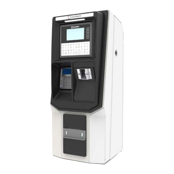
Introduction 1.3 System Architecture Figure 1: Islander Prime 1.3 System Architecture Figure 2 shows a basic diagram of ForeHB system architecture: Figure 2: System Architecture Page 2 MDE-5411A ForeHB Islander Prime Installation Manual · October 2018... -
Page 15: Manual Structure
This section provides the preliminary installation requirements and procedures to be performed before installing the Islander Prime system. Section 4: Installation Procedures This section provides a detailed description of the Islander Prime installation requirements and procedures. Section 5: Maintenance This section provides general maintenance instructions for Islander Prime. -
Page 16: Documentation Conventions
à long terme pour la santé du personnel. A useful guidance, whose purpose is to use the system in a more efficient way. INSIGHT More detailed technical/functional information regarding relevant issues. Page 4 MDE-5411A ForeHB Islander Prime Installation Manual · October 2018... -
Page 17: Important Safety Information
• Use of safety tape, cones or barricades at the affected unit(s) • A total electrical shut-off of the affected unit(s) WARNING Adaptors are not to be used at or be used at or in the vehicle fueling connection. MDE-5411A ForeHB Islander Prime Installation Manual · October 2018 Page 5... - Page 18 Use the OSHA Lockout/Tagout procedures. If you are not familiar with this requirement, refer to this information in the service manual and OSHA documentation. Page 6 MDE-5411A ForeHB Islander Prime Installation Manual · October 2018...
- Page 19 Breakaways must be installed to provide safety protection in the event of a drive-off while the nozzle is connected. CNG dispenser MUST NOT be used in service without approved breakaways being installed. Adapters are not to be used at the vehicle fuel connection. MDE-5411A ForeHB Islander Prime Installation Manual · October 2018 Page 7...
- Page 20 Important Safety Information This page is intentionally left blank. Page 8 MDE-5411A ForeHB Islander Prime Installation Manual · October 2018...
-
Page 21: System Overview
System Overview 3 – System Overview 3.1 General This section provides a detailed description of the Islander Prime system, as well as the available configurations, system specifications, and communication standards. 3.2 System Description The following describes the modules that make up the Islander Prime Fuel Island Controller. -
Page 22: Restrictions And Limits
3.2.6 System Workflow The following provide examples of an operational workflow for self-service at the homebase station. Note: In both options, the driver may print a transaction ticket from the Islander Prime G2 Panel Printer (optional). 3.2.6.1 Refueling Scenario with Fuel Ring A driver stops for fuel at the station. -
Page 23: Islander Prime Structure
3.3 Islander Prime Structure System Overview 3.3 Islander Prime Structure The following describes the components that are part of the Islander Prime structure, including their location and configuration. 3.3.1 Main Components The following provides a description of Islander Prime's main sub units. -
Page 24: Figure 4 Orpay1000
3.3 Islander Prime Structure 3.3.1.2 OrPAY1000 OrPAY1000 is Gasboy’s cost-effective outdoor payment terminal installed directly onto the dispenser or wall mounted next to it for both attended and unattended activities. The terminal’s features suit both retail and commercial fleet markets as a pay-at-the-pump solution for fuel card purchases, forecourt promotions, local accounts, loyalty programs, attendant management, and more. -
Page 25: Figure 5 G2 Panel Printer
The thermal printer is installed at the center of the Islander Prime pedestal door. It includes an integrated paper cutter, paper feeder, paper spool, and an “End of paper” warning sensor. -
Page 26: Figure 6 Communication Interfaces In The Slots
3.3 Islander Prime Structure 3.3.1.4 Communication Interfaces Islander Prime contains three slots for the various optional communication interfaces (1, 2, and 3). There are two types of communication interfaces that can be inserted into the slots; mechanical and electronic. Slots 1 and 2 can house both mechanical and electronic communication interfaces, and slot 3 can only house an electronic communication interface. -
Page 27: Internal Configuration
Controller. 3.4.1 Islander Prime Islander Prime is supplied with the nOrCU (the Gasboy Controller Unit) embedded in the unit. In this configuration, nOrCU acts as a full station controller, providing functions such as authorization unit, central forecourt devices controller, linked to the Head Office, etc. -
Page 28: Automatic Vehicle Identification
3.4.3 Dispensers Islander Prime can support either mechanical or electronic dispensers, in accordance with its configuration. Mechanical dispensers require the installation of an MPI-C interface blade. Electronic... -
Page 29: Emv Option
3.5.3 RF Network Islander Prime IEE 802.15.4 RF network is encrypted, using the AES 128 security standard. MDE-5411A ForeHB Islander Prime Installation Manual · October 2018 Page 17... -
Page 30: Maintenance
Note: Do not pressure wash the Islander Prime. Islander Prime pedestal is locked by key for safety and security. The key should be kept in a secure and safe place. -
Page 31: Technical Specifications And Standards
• Printer • EMV Card Reader and Payment • Insert Card Reader • HID Card Reader • Barcode Reader • ADA (Americans with Disabilities Act) Pedestal • Stainless Steel Pedestal MDE-5411A ForeHB Islander Prime Installation Manual · October 2018 Page 19... -
Page 32: Communication And Security Standards
3.7.2 Communication and Security Standards Islander Prime communicates over the following standards: • RS-232 link • RS-485 link • TCP/IP over Ethernet • IEEE 802.15.4 • AES 128 for RF Network Communication Page 20 MDE-5411A ForeHB Islander Prime Installation Manual · October 2018... -
Page 33: Preliminary Guidelines
Preliminary Guidelines 4 – Preliminary Guidelines 4.1 General This section provides preliminary guidelines for Islander Prime. These include: • Preliminary instructions • Wiring and wire conduits requirements • Installation procedures and requirements depend on the specific fuel dispenser models and the site layout. -
Page 34: Figure 9 Installation Control
L'alimentation du système peut provenir de plus d'une source. Débranchez toutes les sources d'alimentation, les pompes comprises, avant de travailler sur le système. Install Islander Prime in an area in accordance with the safety restrictions (see Figure Installez Islander Prime dans une zone conforme aux restrictions en matière de sécurité... -
Page 35: Station Survey
WARNING The Islander Prime site preparation is the customer’s responsibility. La préparation du site d’Islander Prime est de la responsabilité du client. Do not connect power to Islander Prime and other peripherals, including pumps, until complete installation is inspected and certified. -
Page 36: Locating All Objects
• Locate the roads around the site • Locate the islands and their dispensers • Locate the fuel tanks • Locate the intended position of the Islander Prime pedestal • Draw a basic map of the site with all the objects 4.3.3 Assigning Logical IDs When performing a station survey, assign Logical IDs as described below 4.3.3.1 Fuel Tanks... -
Page 37: Connections
Note: The map methodology and IDs will be used for setup configuration. 4.3.4 Connections All connections to Islander Prime must be performed to the terminal block and to the Ethernet port located at the bottom of the Islander Prime pedestal (see Figure 10). -
Page 38: Conduits
• Forecourt equipment wiring 4.4.1 Requirements The installation of Islander Prime in the island requires digging and setting several conduits in the station ground. The conduits are required for the routing and protection of the different types of cables used in a homebase station with Islander Prime. -
Page 39: Protective Plate
• After completing the installation, all open holes should be resealed. 4.4.2 Protective Plate Islander Prime includes a protective plate below the terminal block in the installation pole. The plate is perforated enabling the insertion of four conduits. • Four conduits of 1-inch diameter •... -
Page 40: Required Conduits
• Grounding - At least 10 mm (OOO AWG) Grounding cable to pump chassis - At least 10 mm (OOO AWG) Grounding cable to Islander Prime pole (Connected to the external chassis grounding post) - Grounding cable to TLG – in accordance with TLG manufacturer instructions •... -
Page 41: Figure 12 Conduit Layout For Mechanical Pump
4.4 Conduits Preliminary Guidelines The following is a diagram of the conduit layout for Islander Prime using a mechanical pump (see Figure 12): Figure 12: Conduit Layout for Mechanical Pump MDE-5411A ForeHB Islander Prime Installation Manual · October 2018 Page 29... -
Page 42: Figure 13 Conduits Layout For Electronic Pump
Preliminary Guidelines 4.4 Conduits The following is a diagram of the conduit layout for Islander Prime using an electronic pump (see Figure 13): Figure 13: Conduits Layout for Electronic Pump Page 30 MDE-5411A ForeHB Islander Prime Installation Manual · October 2018... -
Page 43: Installation
4.4.5 Installation To install conduits in the island, proceed as follows: Determine the location of the Islander Prime pedestal in the island. Dig and prepare passageways for the necessary conduits. Take care to route the following conduits to the junction boxes (J-box): •... -
Page 44: Cable Types
Preliminary Guidelines 4.6 Power Setup 4.5.1 Cable Types The following are the types of cables used for the wiring of the Islander Prime system (see Table Table 4: Islander Prime Cable Types Function Type AC Power from Power cable, 3x1.5 mm 0.118 x 0.06-inch... -
Page 45: Connection Diagram
TLG and dispensers. 4.6.2 Power Supply Setup The Islander Prime power supply can be connected 110 VAC - 220 VAC. The mains cable is first connected to the terminal block. Between the terminal block and power supply, the... -
Page 46: Connecting The Power Equipment
The following describes the wiring procedures for Islander Prime peripherals. 4.7.1 Pump Wiring Islander Prime is capable of driving pump motors through an additional external relay. A separate circuit breaker should be supplied for each dispenser. Note: The protection in communication circuits is part of the operator’s responsibility. -
Page 47: Tlg Wiring
Figure 16: Communications Cable Wiring 4.7.2 TLG Wiring RS-232/LAN is used for communication between the TLG and Islander Prime. Follow these installation requirements when installing the RS-232/LAN communication lines: Note: These requirements must be compatible with the recommendations of the TLG manufacturer. - Page 48 Preliminary Guidelines 4.7 Wiring the Peripherals This page is intentionally blank. Page 36 MDE-5411A ForeHB Islander Prime Installation Manual · October 2018...
-
Page 49: Installation
Prior to actual installation activities, carefully observe the precautions and safety notes detailed in Precautions and Safety Notes and Requirements. 5.2.2 Safety Distances The following shows the safety distances required for the installation of Islander Prime adjacent to the dispensers (see Figure 17). -
Page 50: Installing The Pedestal Base
• A minimum safety separation of 18 inches (0.5-m) from any nearest pump or dispenser. 5.3 Installing the Pedestal Base The Islander Prime pedestal is mounted in the homebase station on a base plate that is fastened to the homebase station concrete floor (see... -
Page 51: Installation Procedure
Various pedestal base heights are available; refer to the specifications of the configuration that you have ordered to determine how far the conduits must reach. 5.3.3 Assembly Parts The following table lists the assembly parts required for the Islander Prime installation (see Table Table 7: Islander Prime Assembly Parts Item No. -
Page 52: Base Plate
Wait the necessary time for the concrete to harden and dry (as per local practice), and then check again that the bottom plate is leveled. Page 40 MDE-5411A ForeHB Islander Prime Installation Manual · October 2018... -
Page 53: Pedestal
Anchor the pedestal base onto the base plate with the four bolts protruding from the inner ground. Secure the pedestal base to the base plate with four M10 flat washers and M10 nuts (step 5 in Figure 20). MDE-5411A ForeHB Islander Prime Installation Manual · October 2018 Page 41... -
Page 54: Sealing Conduits
Note: Install the seal under the barrier plate with the threaded end protruding through the knockout opening. 5.4 Installing Options Islander Prime can be provided in a number of configurations that include a variety of optional add-ons. The following optional add-ons are available: • Barcode reader •... -
Page 55: Barcode Reader Installation
(see Table Figure 22). Table 8: Barcode Reader Assembly Kit Item # Description Barcode Reader Barcode Reader Harness Screw, M4x10 SST+2 Washers Figure 22: Barcode Reader Installation Kit MDE-5411A ForeHB Islander Prime Installation Manual · October 2018 Page 43... -
Page 56: Figure 23 Barcode Reader In Islander Prime Pole Door
To install a barcode reader in the Islander Prime, proceed as follows: Remove the opaque panel covering the glass window in the Islander Prime pole door. Place the barcode reader inside the pole door lined up against the glass window in the door of... -
Page 57: Hid Reader Installation
Wire barcode reader harness P3 to the OrPAY1000 HID harness. 5.4.2 HID Reader Installation The HID Reader (P/N M09680B134) is provided alone, without an assembly kit; it is installed using components already in the Islander Prime pole door (see Figure 29). -
Page 58: Figure 27 Hid Reader Back Plate
5.4 Installing Options To install an HID Reader in the Islander Prime, proceed as follows: Remove the screws affixing the HID Bracket to the Islander Prime pole door. Remove the back plate from the HID Reader. Fasten the HID Reader back plate to the HID Bracket using the flat head screws provided in... -
Page 59: Figure 29 Hid Reader Wiring
Barcode Reader and an HID Reader, connect the Barcode Reader harness to the HID Reader harness as follows (see Figure 29). Figure 29: HID Reader Wiring Use the screws provided to secure the HID Reader to the Islander Prime as follows (see Figure 30). Figure 30: HID Reader in Islander Prime Pole MDE-5411A ForeHB Islander Prime Installation Manual ·... -
Page 60: Insertion Card Reader Installation
Table 9: Insertion Card Reader Assembly Kit Item No. Description Barcode Reader Screw, M4x10 SST+2 Washers 4 Figure 31: Insertion Card Reader Figure 32: Insertion Card Reader (Inside Top View) Page 48 MDE-5411A ForeHB Islander Prime Installation Manual · October 2018... -
Page 61: Figure 33 Insertion Card Reader Label
Installation Figure 33: Insertion Card Reader Label To install an insertion card reader in the Islander Prime, proceed as follows: Remove the screws affixing the front panel to the Islander Prime pole. Place the insertion card reader into the opening light stripe side up. -
Page 62: Cellular Modem Installation
Users have the option to install their own Cellular Modem in the Islander Prime pole door. Gasboy provides a bracket that can be used to mount the Cellular Modem in the pole door. The Cellular Modem installation kit (P/N 819250110) includes the following components ... -
Page 63: Figure 1 Islander Prime
Use the modem harness provided in the installation kit to connect the cellular modem to the Islander Prime. Use the Ethernet cable provided in the installation kit to connect the cellular modem to the Islander Prime 5-port Ethernet switch. MDE-5411A ForeHB Islander Prime Installation Manual · October 2018 Page 51... -
Page 64: G2 Panel Printer Installation
Figure 38): Figure 38: G2 Panel Printer To install a G2 Panel Printer in the Islander Prime, proceed as follows: Disconnect the grounding wire connection in the Islander Prime pole door as follows (see Figure 39): Figure 39: Disconnect Grounding Cable Page 52 MDE-5411A ForeHB Islander Prime Installation Manual ·... -
Page 65: Figure 40 Panel Printer In Islander Prime Pole
Remove the screws affixing the panel covering the printer opening to the Islander Prime pole door. Place the printer into the opening from the outside. Use the screws provided to secure the printer to the inside of the Islander Prime in the provided bracket as follows (see Figure... -
Page 66: Installing Communication Interfaces
The wiring is performed in the Islander Prime terminal block only. The wires should be pulled from the conduits that protrude from the installation base, or in the opposite direction, from the terminal block to the device in the homebase station. -
Page 67: Figure 42 Communication Interface Protective Panel
5.5 Installing Communication Interfaces Installation Remove the protective panel covering the communication interface slots (see Figure 42 Figure 43). Figure 42: Communication Interface Protective Panel Figure 43: Communication Interface Slots (Empty) MDE-5411A ForeHB Islander Prime Installation Manual · October 2018 Page 55... -
Page 68: Figure 44 Communication Interface Blades In Slots
Figure 44: Communication Interface Blades in Slots Note: If you are adding a mechanical interface, it may be inserted into slot 1 or slot 2 only. Tighten the front screws in each blade. Page 56 MDE-5411A ForeHB Islander Prime Installation Manual · October 2018... -
Page 69: Wiring Requirements
Figure 45). Figure 45: Communication Interface Protective Panel With Interface 5.5.2 Wiring Requirements Mark each cable at both ends with a number or sign that will identify its functionality. MDE-5411A ForeHB Islander Prime Installation Manual · October 2018 Page 57... -
Page 70: Mechanical Dispenser Connections
Islander Prime. The following describes the required wiring connections between the mechanical dispenser interface and Islander Prime. Figure 46: Mechanical Dispenser Interface The following is a detailed wiring diagram between Islander Prime terminal block and the pump components (see Figure... - Page 71 Without this authorization signal, the electric valve (or pump) will not open and the sales transaction will not begin. Islander Prime switches the AC power signal to the valve. When the dispenser receives the authorization signal, it enables the fuel flow.
-
Page 72: Pulser Connections
5.5.4 Pulser Connections The following describes the required wiring connections between the pulser in the mechanical pump and Islander Prime. The system can accept many types of pulsers; contact Gasboy for more information. There are two types of pulser: • Electronic pulser •... -
Page 73: Electronic Dispenser Connections
5.5.4.2 Mechanical Pulser - Two-Wire Pulser The following is a schematic diagram of the connections between the terminal block and a two-wire pulser (see Figure 50): Figure 50: Two-Wire Pulser Wiring Connections MDE-5411A ForeHB Islander Prime Installation Manual · October 2018 Page 61... -
Page 74: Figure 51 Tokheim Electronic Interface
The wiring in the terminal block differs in accordance with the type of electronic pump installed in the homebase station. There are several types of electronic pumps. Electronic dispenser interfaces may be installed in any of the three slots in the Islander Prime. The following describes the wiring connections of the available pumps. -
Page 75: Figure 52 Tokheim Electronic Interface - Wiring Diagram
5.5 Installing Communication Interfaces Installation The following shows the specific wiring connections between Islander Prime and the Tokheim pump nozzle, and the terminals that differ from the mechanical pump (see Figure 52): Figure 52: Tokheim Electronic Interface - Wiring Diagram... -
Page 76: Figure 53 Current Loop Electronic Pump - Wiring Diagram
5.5 Installing Communication Interfaces 5.5.5.2 Current Loop The following shows the specific wiring connections between Islander Prime and the Current Loop pump nozzle, the terminals that differ from the mechanical pump, and the serial connection between two Current Loop pumps and the terminal block (see... -
Page 77: Figure 54 Rs-485 Electronic Interface
The RS-485 electronic interface appears as follows (see Figure 54): Figure 54: RS-485 Electronic Interface The following show the parallel connection between two Gasboy RS-485 pumps and the terminal block (see Figure 55): Figure 55: RS-485 Device - Wiring Diagram MDE-5411A ForeHB Islander Prime Installation Manual ·... -
Page 78: Figure 56 Rs-232/Rs-422 Electronic Interface
Installation 5.5 Installing Communication Interfaces • In the junction box for the Gasboy electronic pump, connect the Red Tx+ to the White Rx+, and connect the Green Tx- to the Black Rx. • Run one wire from the + and one wire from the - to the proper terminal blocks in the Islander Prime unit. -
Page 79: Post-Installation Checklist
- Are the cables correctly routed in the island? - Are the communication lines under the maximum allowable distance? RS-232: 50 feet (15 m) RS-485: 330 feet (100 m) MDE-5411A ForeHB Islander Prime Installation Manual · October 2018 Page 67... -
Page 80: Islander Prime Setup
The OrPAY1000 display should not be exposed to direct sunlight. It is therefore highly recommended to add an awning. 5.7 Islander Prime Setup For information on how to set up Islander Prime once installed, refer to the MDE-4817 SiteOmat Installation and Maintenance Manual. Page 68... -
Page 81: Lan Commverter Setup
This section provides instructions for setting up the Islander Prime LAN CommVerter. To access the setup site for Islander Prime, proceed as follows: Open an Internet browser and enter the default IP address provided by Gasboy. The CommVerter Setup homepage opens with a login dialog box (see Figure 58). -
Page 82: Home Page
Pump 2 Version Pump software version for the PI in Slot 2 Pump 3 Version Pump software version for the PI in Slot 3 Location Location of the Islander Prime Page 70 MDE-5411A ForeHB Islander Prime Installation Manual · October 2018... -
Page 83: Setup
• Click Submit to save the changes locally. Note: Clicking Submit saves the configuration temporarily on a local level. To commit the changes permanently, ensure to save everything via the Save tab. MDE-5411A ForeHB Islander Prime Installation Manual · October 2018 Page 71... -
Page 84: General Setup
Disable: Device will not automatically reset. NoData Timeout (sec) No Data Timeout timeout interval, in seconds. Note: Make sure that no pumps at the station are actively fueling before changing the date or time. Page 72 MDE-5411A ForeHB Islander Prime Installation Manual · October 2018... -
Page 85: Oric Config
• Click Submit to save the changes locally. Note: Clicking Submit saves the configuration temporarily on a local level. To commit the changes permanently, make sure to save everything via the Save tab. MDE-5411A ForeHB Islander Prime Installation Manual · October 2018 Page 73... - Page 86 If set to 0, the channel will not reset. Note: If the channel configuration is not displayed properly after saving all changes and resetting the device, clear your browser cache and reload the page. Page 74 MDE-5411A ForeHB Islander Prime Installation Manual · October 2018...
-
Page 87: Log Level
Click the Log Level tab. The following screen opens (see Figure 63): Figure 63: Log Level Tab The Log Levels section defines settings for logs that are sent to Gasboy Note: Please consult with Gasboy’s Customer Services prior to defining the Log Levels settings. The following actions are available: •... -
Page 88: Save
Click the Save tab. The following screen opens (see Figure 64): Figure 64: Save Tab Click Apply. The following dialog box opens (see Figure 65): Figure 65: Confirm Save Dialog Box Page 76 MDE-5411A ForeHB Islander Prime Installation Manual · October 2018... -
Page 89: Figure 66 Reset Device Dialog
Click OK to confirm. Note: The dialog box screenshots in this procedure are for demonstration purposes only, including the IP address in the headers. Use the IP address provided to you by Gasboy when performing this procedure. MDE-5411A ForeHB Islander Prime Installation Manual · October 2018... -
Page 90: Software Upload
From the File Type drop-down, select the file type that you want to upload. Click Choose File to launch a browser window, and browse to the file path of the software version to upload. Select the file and click Open. Page 78 MDE-5411A ForeHB Islander Prime Installation Manual · October 2018... -
Page 91: Figure 69 Confirm Upload Dialog
6.4 Software Upload LAN CommVerter Setup Click Upload. The following dialog box opens (see Figure 69): Figure 69: Confirm Upload Dialog Box Click OK to confirm and upload the file. MDE-5411A ForeHB Islander Prime Installation Manual · October 2018 Page 79... - Page 92 LAN CommVerter Setup 6.4 Software Upload This page is intentionally blank. Page 80 MDE-5411A ForeHB Islander Prime Installation Manual · October 2018...
-
Page 93: Maintenance
Maintenance 7 – Maintenance 7.1 General Islander Prime itself as a standalone unit should be cleaned periodically at short intervals, due to the harsh environment of the homebase station where it operates. 7.2 OrPAY1000 and Islander Prime The following instructions are valid for the OrPAY1000 front panel and the Islander Prime pedestal. -
Page 94: Printer
Figure 70: Paper Lock Lever Remove the cleaning card from its packaging. Insert the cleaning card manually into the printer paper slot. Press the green paper-lock lever back to its initial position. Page 82 MDE-5411A ForeHB Islander Prime Installation Manual · October 2018... - Page 95 Print a receipt with at least ten rows of text. Check readability and verify the text font is clear. Note: If readability is still poor, repeat the cleaning procedure with a new cleaning card. MDE-5411A ForeHB Islander Prime Installation Manual · October 2018 Page 83...
- Page 96 Maintenance 7.4 Printer This page is intentionally blank. Page 84 MDE-5411A ForeHB Islander Prime Installation Manual · October 2018...
-
Page 97: Troubleshooting
8 – Troubleshooting 8.1 General This section provides a list of common pump/system problems that may be encountered when using the Islander Prime system, as well as corrective actions for problems related to the system and its peripherals. 8.2 Islander Prime The following describes Islander Prime troubleshooting procedures and appropriate corrective actions. -
Page 98: Mechanical Pump Does Not Fuel
Troubleshooting 8.2 Islander Prime 8.2.2 Mechanical Pump Does Not Fuel The following table describes the Islander Prime troubleshooting procedure and appropriate corrective actions when the mechanical pump does not fuel (see Table 24): Table 24: Mechanical Pump Does Not Fuel... - Page 99 Disconnect the pulser If pulses are received during refueling, board and short the pulse-in replace pump pulser. If not, replace MPI-C • Faulty pulser wires to simulate board. pulses. MDE-5411A ForeHB Islander Prime Installation Manual · October 2018 Page 87...
-
Page 100: No Control Over Fueling
Troubleshooting 8.3 OrPAY1000 8.2.3 No Control Over Fueling The following table describes the Islander Prime troubleshooting procedure and appropriate corrective actions when there is no control over fueling (see Table 25): Table 25: No Control Over Fueling Fault Probable Cause... - Page 101 LAN to 3x 485 CommVerter. It should be inserted in a socket on the LAN to 3x 485 CommVerter main board. Replace the 5-LAN switch. MDE-5411A ForeHB Islander Prime Installation Manual · October 2018 Page 89...
-
Page 102: Printer
Faulty power Check power supply outputs using a Replace power supply. supply digital voltmeter. The output voltage should be 24 VDC. Faulty printer Replace the printer. Page 90 MDE-5411A ForeHB Islander Prime Installation Manual · October 2018... - Page 103 Paper is not being cut at the Incorrect SiteOmat Check SiteOmat printing settings. Set SiteOmat printing end of the printing. setting settings accordingly. Faulty printer Replace printer cutter. cutter Faulty printer Replace printer. MDE-5411A ForeHB Islander Prime Installation Manual · October 2018 Page 91...
-
Page 104: Communication
If no activity on the LAN port, authorization at Incorrect nozzle reader • Check the check the cable and/or change programming of the the pumps. setup. the port on the 5-port switch. WNRs. Page 92 MDE-5411A ForeHB Islander Prime Installation Manual · October 2018... - Page 105 9600, 8, None, 1, None and D6 as connection type). By default the port is set to 10001 – confirm similar setting for the TLS bus in the controller setup. MDE-5411A ForeHB Islander Prime Installation Manual · October 2018 Page 93...
-
Page 106: Fuelpoint
• LAN switch • From main board ETH1/2 to LAN switch • From LAN to PC • From com card to LAN switch • From com card to main board J23 Page 94 MDE-5411A ForeHB Islander Prime Installation Manual · October 2018... - Page 107 8.6 FuelPoint Troubleshooting This page is intentionally blank. MDE-5411A ForeHB Islander Prime Installation Manual · October 2018 Page 95...
- Page 108 Tokheim Holding B.V. Corporation. © 2018 Gilbarco Inc. 7300 West Friendly Avenue · Post Office Box 22087 Greensboro, North Carolina 27420 Phone (336) 547-5000 · http://www.gilbarco.com · Printed in the U.S.A. MDE-5411A ForeHB Islander Prime Installation Manual · October 2018...
Need help?
Do you have a question about the Islander Prime and is the answer not in the manual?
Questions and answers