
Related Manuals for Sokkia CX Series


Summary of Contents for Sokkia CX Series
- Page 1 SURVEYING INSTRUMENTS CX series CX-101 CX-102/102L CX-103 CX-105/105L CX-106 CX-107 Compact X-ellence Station CLASS 3R Laser Product CLASS 2 Laser Product CLASS 1 Laser Product OPERATOR'S MANUAL 21403 99160...
- Page 2 S Li-ion Li-ion :This is the mark of the Japan Surveying Instruments Manufacturers Association.
- Page 3 SURVEYING INSTRUMENTS CX series CX-101 CX-102/102L CX-103 CX-105/105L CX-106 CX-107 Compact X-ellence Station CLASS 3R Laser Product CLASS 2 Laser Product CLASS 1 Laser Product OPERATOR’S MANUAL Thank you for selecting the CX-101/102/102L/103/105/105L/106/107. Please read this operator's manual carefully before using this product.
- Page 4 Notes regarding manual style • Except where stated, “CX” means CX-101/102/102L/103/105/105L/106/107. • The CX Series is available in "standard", "High Temperature", and "Low Temperature" models. Users with a "Low Temperature Model" should read the additional precautions specific to use under low temperatures.
- Page 5 • Measurement procedures are based on continuous measurement. Some information about procedures when other measurement options are selected can be found in “Note” ( • indicates functions/options not available on all products. Contact your local dealer for availability with your product. •...
-
Page 6: Table Of Contents
CONTENTS 1. PRECAUTIONS FOR SAFE OPERATION ......1 2. PRECAUTIONS ..........5 3. - Page 7 CONTENTS 14. COORDINATE MEASUREMENT ....... 79 15. SETTING-OUT MEASUREMENT ....... 82 15.1 Coordinates Setting-out Measurement .
- Page 8 CONTENTS 28.3 Recording Angle Measurement Data ..... . . 204 28.4 Recording Distance Measurement Data ....205 28.5 Recording Coordinate Data .
- Page 9 CONTENTS 36.3 Target system ......... 279 36.4 Power supplies .
- Page 10 viii...
-
Page 11: Precautions For Safe Operation
1. PRECAUTIONS FOR SAFE OPERATION For the safe use of the product and prevention of injury to operators and other persons as well as prevention of property damage, items which should be observed are indicated by an exclamation point within a triangle used with WARNING and CAUTION statements in this operator’s manual. - Page 12 1. PRECAUTIONS FOR SAFE OPERATION General Warning Do not use the unit in areas exposed to high amounts of dust or ash, in areas where there is inadequate ventilation, or near combustible materials. An explosion could occur. Do not perform disassembly or rebuilding. Fire, electric shock, burns or hazardous radiation exposure could result.
- Page 13 1. PRECAUTIONS FOR SAFE OPERATION Power Supply Warning Do not place articles such as clothing on the battery charger while charging batteries. Sparks could be induced, leading to fire. Do not use batteries other than those designated. An explosion could occur, or abnormal heat generated, leading to fire.
- Page 14 1. PRECAUTIONS FOR SAFE OPERATION Tripod Caution When mounting the instrument to the tripod, tighten the centering screw securely. Failure to tighten the screw properly could result in the instrument falling off the tripod, causing injury. Tighten securely the leg fixing screws of the tripod on which the instrument is mounted.
-
Page 15: Precautions
2. PRECAUTIONS Tribrach Clamp • When the instrument is shipped, the tribrach clamp is held firmly in place with a locking screw to prevent the instrument from shifting on the tribrachs. Before using the instrument the first time, loosen this screw with a screwdriver. - Page 16 2. PRECAUTIONS Vertical and horizontal clamps • Always fully release the vertical/horizontal clamps when rotating the instrument or telescope. Rotating with clamp(s) partially applied may adversely affect accuracy. Backing up data • Data should be backed up (transfered to an external device etc.) on a regular basis to prevent data loss.
- Page 17 2. PRECAUTIONS Other precautions • Close the external interface hatch before starting measurement. Otherwise, ambient light entering the USB port may adversely affect measurement results. • If the CX is moved from a warm place to an extremely cold place, internal parts may contract and make the keys difficult to operate.
- Page 18 2. PRECAUTIONS • When the instrument is not used for a long time, check it at least once every 3 months. "35. CHECKS AND ADJUSTMENTS" • When removing the CX from the carrying case, never pull it out by force. The empty carrying case should be closed to protect it from moisture.
-
Page 19: Laser Safety Information
3. LASER SAFETY INFORMATION CX is classified as the following class of Laser Product according to IEC Standard Publication 60825-1 Ed.2.0: 2007 and United States Government Code of Federal Regulation FDA CDRH 21CFR Part 1040.10 and 1040.11 (Complies with FDA performance standards for laser products except for deviations pursuant to Laser Notice No.50, dated June 24, 2007.) •... - Page 20 3. LASER SAFETY INFORMATION • If an eye injury is caused by exposure to the laser beam, seek immediate medical attention from a licensed ophthalmologist. • Never look at the laser beam through a telescope, binoculars or other optical instruments. Doing so could cause permanent eye damage. •...
-
Page 21: Cx Functions
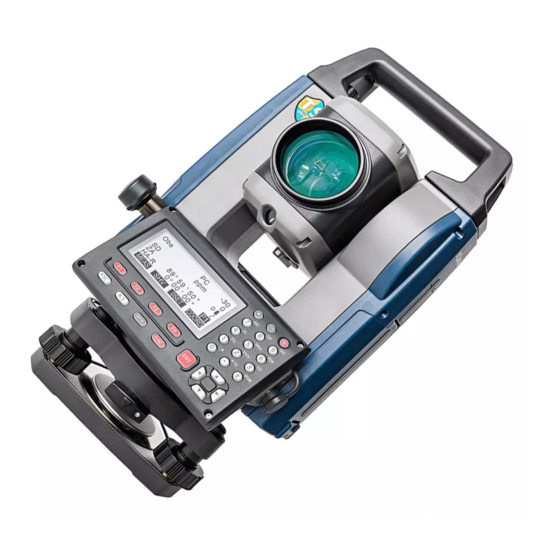
4. CX FUNCTIONS Parts of the Instrument CX Series Handle Bluetooth antenna External interface hatch (USB port) Instrument height mark Battery cover Operation panel 7A Serial connector 7B Combined communications and power source connector Circular level Circular level adjusting screws... - Page 22 4. CX FUNCTIONS CX-101/102 and Low Temperature Models only Sighting collimator Use sighting collimator to aim the CX in the direction of the measurement point. Turn the instrument until the triangle in the sighting collimator is aligned with the target. Instrument height mark The height of the CX is as follows: •...
- Page 23 4. CX FUNCTIONS Operation panel "5.1 Basic Key Operation" Illumination key Star key Power key Display unit Softkey selection Guide light Guide light Guide light Setting-out measurement etc. can be carried out effectively using the Guide light. The Guide light is composed of a light that is divided into a red and a green light.
- Page 24 4. CX FUNCTIONS Guide light status Light status Meaning (From position of poleman) Move target left Green (From position of poleman) Move target right Red and Green Target is at correct horizontal position When the guide light is turned ON, it is displayed as a symbol in the display unit.
-
Page 25: Mode Diagram
4. CX FUNCTIONS Mode Diagram Star key Mode L - p o i n t e r O f f Dist+Coord Note R e f l e c t o r P r i s m View L a s e r p l u m : O f f Deletion L a s e r l e v. -
Page 26: Bluetooth Wireless Technology
4. CX FUNCTIONS Bluetooth Wireless Technology • Bluetooth communication is only possible with instruments incorporating the Bluetooth module. • Use of this technology must be authorized according to telecommunications regulations of the country where the instrument is being used. Contact your local dealer in advance. - Page 27 4. CX FUNCTIONS When using the in proximity to IEEE802.11b or IEEE802.11g standard wireless LAN devices, turn off all devices not being used. • Interference may result, causing transmission speed to slow or even disrupting the connection completely. Turn off all devices not being used. Do not use the CX in proximity to microwaves.
-
Page 28: Basic Operation
5. BASIC OPERATION Basic Key Operation Learn basic key operations here before you read each measurement procedure. Location of operation keys on the panel : "4.1 Parts of the Instrument" Power ON / OFF {ON} Power On {ON} Power Off (Press and hold: About 1 second) Lighting up the display unit and key... - Page 29 5. BASIC OPERATION Softkey operation Softkeys are displayed on the bottom line of the screen. {F1} to {F4} Select the function matching the softkeys {FUNC} Toggle between OBS mode screen pages (when more than 4 softkeys are allocated) Inputting letters/figures {SHIFT} Switch between numeric and alphabetic characters.
- Page 30 5. BASIC OPERATION 6. Press {5} once. JOB details "M" is displayed. Press {ENT } to JOB name complete inputting. JOB M SCALE: 1.00000000 Selecting options { }/{ } Up and down cursor { }/{ } Right and left cursor/Select other option {ENT} Accept the option Example: Select a reflector type...
-
Page 31: Display Functions
5. BASIC OPERATION Display Functions Status screen Instrument name CX-103 rec 9999 S/N 123456 Application Ver. XXX-XX-XX software XXX-XX-XX version Job.JOB1 DATA CNFG OBS mode screen Target *5 Prism constant value Atmospheric correction factor Distance *1 Remaining battery power *4 Vertical angle *2 Tilt angle compensation *6 HA-R... - Page 32 5. BASIC OPERATION * 2 Vertical angle Switching vertical angle display status: "33.1 Configuration -Config Mode-" ZA : Zenith angle (Z=0) VA : Vertical angle (H=0/H=±90) To switch vertical angle/slope in %, press [ZA/%] * 3 Horizontal angle Press [R/L] to switch the display status. HA-R: Horizontal angle right HA-L: Horizontal angle left * 1,2,3...
- Page 33 5. BASIC OPERATION :Laser-pointer is selected and ON :Guide light is selected and ON *8 Bluetooth communication status : Connection established (“Mode” is set to “Slave”) : Connection established (“Mode” is set to “Master”) (flashing): Connecting (“Mode” is set to “Slave”) (flashing): Connecting (“Mode”...
-
Page 34: Star Key Mode
5. BASIC OPERATION Star Key Mode Pressing the Star key { } displays the Star Key menu. In the Star Key mode, you can start the measurement program from the Entry menu and change the setting commonly used for measuring. E n t r y m e n u R e f l e c t o r P r i s m... -
Page 35: Using The Battery
6. USING THE BATTERY Battery Charging The battery has not been charged at the factory. • Do not short circuit. Heat or ignition could result. • Batteries cannot be charged, even when the charging lamp is flashing, when the temperature is outside the charging temperature range. Always charge batteries within the charging temperature range. - Page 36 6. USING THE BATTERY • Slots 1 and 2: The charger starts charging the battery mounted first. If you place two batteries in the charger, the battery in slot 1 is charged first, and then the battery in slot 2. (step 2) •...
-
Page 37: Installing/Removing The Battery
6. USING THE BATTERY Installing/Removing the Battery Mount the charged battery. • Use the provided battery BDC70 for this instrument. • When removing the battery, turn the power off. • When installing/removing the battery, make sure that moisture or dust particles do not come in contact with the inside of the instrument. -
Page 38: Setting Up The Instrument
7. SETTING UP THE INSTRUMENT • Mount the battery in the instrument before performing this operation because the instrument will tilt slightly if the battery is mounted after levelling. Centering PROCEDURE Centering with the optical plummet eyepiece 1. Make sure the legs are spaced at equal intervals and the head is approximately level. - Page 39 7. SETTING UP THE INSTRUMENT 3. Looking through the optical Focussing on the survey point plummet eyepiece, turn the optical plummet eyepiece to focus on the Focussing reticle. on the Turn the optical plummet focussing reticle ring to focus on the survey point. PROCEDURE Centering with the laser plummet ( 1.
-
Page 40: Levelling
7. SETTING UP THE INSTRUMENT 6. Press [L-OFF] to turn the laser plummet off. Alternatively, press {ESC} to return to the previous screen. The laser plummet will switch off automatically. • Visibility of the laser spot may be affected when operating in direct sunlight. In this event, provide shade for the survey point. - Page 41 7. SETTING UP THE INSTRUMENT 3. Press {ON} to power on "9. POWER ON/OFF" • The circular level is displayed on the screen. • “ ” indicates bubble in circular level. The range of the inside circle is ±4' and the range of the outside circle is ±6'.
- Page 42 7. SETTING UP THE INSTRUMENT 6. Set the tilt angle to 0° using foot screws A and B for the X direction and levelling screw C for the Y direction. 7. Loosen the centering screw slightly. Looking through the optical plummet eyepiece, slide the instrument over the tripod head until the survey point is exactly...
- Page 43 7. SETTING UP THE INSTRUMENT 2. Loosen the horizontal clamp to turn the upper part of the instrument until the plate level is parallel to a line between levelling foot screws A and B. Center the air bubble using levelling foot screws A and B simultaneously.
- Page 44 7. SETTING UP THE INSTRUMENT 6. Loosen the centering screw slightly. Looking through the optical plummet eyepiece, slide the instrument over the tripod head until the survey point is exactly centered in the reticle. Retighten the centering screw securely. • When the instrument was centered using the laser plummet, emit the plummet beam again to check position...
-
Page 45: Focussing And Target Sighting
8. FOCUSSING AND TARGET SIGHTING • When sighting the target, strong light shining directly into the objective lens may cause the instrument to malfunction. Protect the objective lens from direct light by attaching the lens hood. Observe to the same point of the reticle when the telescope face is changed. PROCEDURE 1. - Page 46 8. FOCUSSING AND TARGET SIGHTING 4. Readjust the focus with the focussing ring until there is no parallax between the target image and the reticle. Eliminating parallax This is the relative displacement of the target image with respect to the reticle when the observer’s head is moved slightly before the eyepiece.
-
Page 47: Power On/Off
9. POWER ON/OFF Setting “V manual”: "33.1 Configuration -Config Mode-", Setting/changing password: "33.4 Changing Password" PROCEDURE Power ON 1. Press {ON}. When the power is switched on, a self-check is run to make sure the instrument is operating normally. • When password is set, the display appears as at right. - Page 48 9. POWER ON/OFF • When “Resume” in “Instr. config” is set to “On”, the screen previous to power off is displayed (except when missing line measurement was being performed). "33.1 Configuration -Config Mode-" • “Tilt crn” in “Obs. condition” should be set to “No” if the display is unsteady due to vibration or strong wind.
-
Page 49: Connecting To External Devices
10. CONNECTING TO EXTERNAL DEVICES 10.1 Necessary settings for Bluetooth communication Bluetooth wireless technology allows the CX to communicate wirelessly with other Bluetooth devices. Bluetooth wireless communication settings are performed in “Comms setup” in Config Mode. PROCEDURE Basic Settings 1. Select ”Comms setup” in Config mode 2. - Page 50 10. CONNECTING TO EXTERNAL DEVICES 6. Set "Authentication". Select "Yes" or "No". 7. Set "Passkey". Set the same passkey as that for your Bluetooth device. • Up to 16 numeral characters can be input. "0123" is the factory setting. Input characters will be displayed as asterisks (e.g.
- Page 51 10. CONNECTING TO EXTERNAL DEVICES 3. Select "Link device list". Wireless Bluetooth setup Link device list My device info 4. Register your Bluetooth device(s). Link device list Select a device and press [EDIT] DEVICE1 to update related information. DEVICE2 DEVICE3 DEVICE4 EDIT •...
-
Page 52: Establishing A Connection Between The Cx And Paired Bluetooth Device
10. CONNECTING TO EXTERNAL DEVICES PROCEDURE Displaying Bluetooth information for the CX 1. Select "Comms setup" in Config mode. 2. Set "Wireless" to "Yes". 3. Select "My device info". Wireless The Bluetooth information for the Bluetooth setup CX is displayed. The "BD ADDR" Link device list My device info for the CX must be registered on... - Page 53 10. CONNECTING TO EXTERNAL DEVICES 2. Press [ ] in the fourth page of OBS mode screen. The Bluetooth module in the CX powers on and connection starts. HA-R The Bluetooth icon indicates communication status. "5.2 Display Functions" HA-R • When "Mode" in "Bluetooth setup" is set to "Slave", the establishing of a connection can only be initiated from the "Master"...
-
Page 54: Measurement Using Bluetooth Communication
10. CONNECTING TO EXTERNAL DEVICES 10.3 Measurement using Bluetooth communication Data collectors can also be set as companion devices for wireless communication and can be used to initiate measurement. PROCEDURE Performing measurement using a data collector 1. Complete the necessary settings for Bluetooth communication. -
Page 55: Registering/Outputting Data Using Bluetooth Communication
10. CONNECTING TO EXTERNAL DEVICES 10.4 Registering/Outputting data using Bluetooth communication It is possible to set a computer as the companion device and register known point data or output JOB data via wireless communication. PROCEDURE Entering known point coordinate data from an external instrument 1. - Page 56 10. CONNECTING TO EXTERNAL DEVICES PROCEDURE Outputting JOB data to a host computer 1. Complete the necessary settings for Bluetooth communication. "10.1 Necessary settings for Bluetooth communication" 2. Verify the current connection status by checking the Bluetooth icon in the OBS mode screen. "10.2 Establishing a connection between the CX and paired Bluetooth device"...
-
Page 57: Connecting Via Communication Cable
10. CONNECTING TO EXTERNAL DEVICES 10.5 Connecting via Communication Cable PROCEDURE Basic cable settings 1. Connect the CX to the external device using the cable. Cables: "36.2 Optional accessories" 2. Select “Comms setup” in Config mode. Set communication conditions. "33.1 Configuration -Config Mode-"... -
Page 58: Angle Measurement
11. ANGLE MEASUREMENT This section explains the procedures for basic angle measurement. 11.1 Measuring the Horizontal Angle between Two Points (Horizontal Angle 0°) Use the “0SET” function to measure the included angle between two points. The horizontal angle can be set to 0 at any direction. PROCEDURE 1. -
Page 59: Setting The Horizontal Angle To A Required Value
11. ANGLE MEASUREMENT 11.2 Setting the Horizontal Angle to a Required Value (Horizontal Angle Hold) You can reset the horizontal angle to a required value and use this value to find the horizontal angle of a new target. PROCEDURE Entering the horizontal angle 1. - Page 60 11. ANGLE MEASUREMENT PROCEDURE Entering the coordinate 1. Press [H-SET] on the second Set H angle page of the OBS mode and select Angle "Coord." Coord 2. Set the known point coordinate. S E T H a n g l e / B S Enter the coordinate for the first N B S : 1 0 0 .
-
Page 61: Angle Measurement And Outputting The Data
11. ANGLE MEASUREMENT 11.3 Angle Measurement and Outputting the Data The following explains angle measurement and the features used to output measurement data to a computer or peripheral equipment. Bluetooth communication: "10. CONNECTING TO EXTERNAL DEVICES" Communication cables: "36.2 Optional accessories" Output format and command operations: "Communication manual"... -
Page 62: Distance Measurement
12. DISTANCE MEASUREMENT Perform the following settings as preparation for distance measurement. • Distance measurement mode • Target type • Prism constant correction value • Atmospheric correction factor • EDM ALC "33.1 Configuration -Config Mode-"/"33.2 EDM Settings" CAUTION • When using the Laser-pointer function, be sure to turn OFF the output laser after distance measurement is completed. -
Page 63: Returned Signal Checking
12. DISTANCE MEASUREMENT 12.1 Returned Signal Checking • Check to make sure that sufficient reflected light is returned by the reflective prism sighted by the telescope. Checking the returned signal is particularly useful when performing long distance measurements. • When the light intensity is sufficient even though the center of the reflective prism and the reticle are slightly misaligned (short distance etc.), “*”... -
Page 64: Distance And Angle Measurement
12. DISTANCE MEASUREMENT 4. Press {ESC} to finish signal checking and return to Obs Mode. • When is displayed persistently, contact your local dealer. • If no key operations are performed for two minutes, the display automatically returns to the OBS mode screen. 12.2 Distance and Angle Measurement An angle can be measured at the same time as the distance. -
Page 65: Recalling The Measured Data
12. DISTANCE MEASUREMENT 3. Press [STOP] to quit distance measurement. • Each time [SHV] is pressed, SD (Slope distance), HD (Horizontal distance) and VD (Height difference) are displayed alternately. MEAS 0SET COORD • If the single measurement mode is selected, measurement automatically stops after a single measurement. -
Page 66: Distance Measurement And Outputting The Data
12. DISTANCE MEASUREMENT 2. Press [CALL]. The stored data that is most recently measured is displayed. • If you have pressed [SHV] beforehand, the distance values are converted into the horizontal distance, elevation difference, and the slope distance and recalled. 3. -
Page 67: Coordinate Measurement And Outputting The Data
12. DISTANCE MEASUREMENT 4. Press [HVDOUT-T] or [HVDOUT- S] to measure the distance and output the data to peripheral equipment. 5. Press [STOP] to stop outputting data and return to Obs Mode. 12.5 Coordinate Measurement and Outputting the Data The following explains coordinate measurement and the features used to output measurement data to a computer or peripheral equipment. - Page 68 12. DISTANCE MEASUREMENT 4. Press [NEZOUT-T] or [NEZOUT- S] to measure the distance and output the data to peripheral equipment. • When the Distance Measurement mode is set to "Tracking" in the EDM Settings, the measured data cannot be output by pressing [NEZOUT-T]. 5.
-
Page 69: Rem Measurement
12. DISTANCE MEASUREMENT 12.6 REM Measurement An REM measurement is a function used to measure the height to a point where a target cannot be directly installed such as power lines, overhead cables and bridges, etc. The height of the target is calculated using the following formula. Ht = h1 + h2 h2 = S sin θ... - Page 70 12. DISTANCE MEASUREMENT The measured distance data (SD), vertical angle (ZA), and horizontal angle (HA-R) are displayed. Press [STOP] to stop the measurement. 3. In the second page of OBS mode screen, press [MENU], then select Area calc. "REM". S-O Line S-O Arc P-Project PT to line...
- Page 71 12. DISTANCE MEASUREMENT • Press [HT] to enter an Height instrument height (HI) and a 0.000m target height (HR). 0.000m • When [REC] is pressed, REM data is saved. "28. RECORDING DATA - TOPO MENU -" • Press [HT/Z] on the second page of the REM measurement to display the Z coordinate for the height from the ground to the...
-
Page 72: Setting Instrument Station
13. SETTING INSTRUMENT STATION It is possible to set from the instrument station data to the backsight angle in a series of procedures. Setting Instrument Station Data • Key input "13.1 Entering Instrument Station Data and Azimuth Angle" Step 3 •... -
Page 73: Entering Instrument Station Data And Azimuth Angle
13. SETTING INSTRUMENT STATION 13.1 Entering Instrument Station Data and Azimuth Angle Before coordinate measurement, enter instrument station coordinates, the instrument height, target height, and azimuth angle. PROCEDURE 1. First measure the target height and instrument height with a tape measure, etc. - Page 74 13. SETTING INSTRUMENT STATION • Press [RESEC] to measure instrument station coordinates by resection measurement. "13.2 Setting Instrument Station Coordinate with resection measurement" 4. Press [BS AZ] in the screen of step 3 to proceed to azimuth angle input. • Press [BS NEZ] to calculate azimuth angle from backsight coordinates.
- Page 75 13. SETTING INSTRUMENT STATION PROCEDURE Reading in Registered Coordinate Data Known point data, coordinate data and instrument station data in the current JOB and Coordinate Search JOB can be read in. Confirm that the correct JOB containing the coordinates you want to read in is already selected in Coordinate Search JOB in Data Mode.
- Page 76 13. SETTING INSTRUMENT STATION • You can edit the coordinate data that was read in. Editing does not affect the original coordinate data. After editing, the point name is no longer displayed. • The point name that was read in is displayed until the current JOB is changed. •...
- Page 77 13. SETTING INSTRUMENT STATION PROCEDURE Coordinate Data Search (Partial match) 1. Press [Search] in the registered coordinate data list screen. All coordinate data that includes characters and numbers entered in step 2 is displayed. 2. Enter search criteria. 1 0 0 Enter the following items.
- Page 78 13. SETTING INSTRUMENT STATION 2. Press [BS NEZ] after entering the Backsight instrument station data to enter a 100.000 NBS: backsight point coordinate. 100.000 EBS: <Null> ZBS: • When you wish to read in the LOAD registered coordinate data, press [LOAD]. ""13.1 Entering Instrument Station Data and Azimuth Angle"...
- Page 79 13. SETTING INSTRUMENT STATION • Press [REC] to record the following data. Instrument station data, backsight station data, known point data, and angle measurement data (distance measurement data when [MEAS] is pressed) • When storing the azimuth angle in the current JOB, press [REC]. "28.2 Recording Backsight Point",...
-
Page 80: Setting Instrument Station Coordinate With Resection Measurement
13. SETTING INSTRUMENT STATION 13.2 Setting Instrument Station Coordinate with resection measurement Resection is used to determine the coordinates of an instrument station by performing multiple measurements of points whose coordinate values are known. Registered coordinate data can be recalled and set as known point data. Residual of each point can be checked, if necessary. - Page 81 13. SETTING INSTRUMENT STATION 13.2.1 Coordinate Resection Measurement Observe existing points with known coordinate data to calculate the coordinate value for the instrument station. • Between 2 and 10 known points can be measured by distance measurement, and between 3 and 10 known points by angle measurement. PROCEDURE 1.
- Page 82 13. SETTING INSTRUMENT STATION 6. Input coordinates for the first 1 s t P T known point and press [NEXT] to 2 0 . 0 0 0 move to the second point. 3 0 . 0 0 0 4 0 . 0 0 0 1 0 .
- Page 83 13. SETTING INSTRUMENT STATION 10. If there are problems with the results of a point, align the cursor - 0 . 0 0 1 0 . 0 0 1 1 s t with that point and press [OMIT]. 0 . 0 0 5 0 .
- Page 84 13. SETTING INSTRUMENT STATION • Pressing [REC] displays the backsight point recording screen. Press [OK] to the HA-R 1 2 0 1.400m following data. Instrument station data, backsight station data, known point data, and angle measurement data (distance measurement data when [MEAS] is pressed) Pressing [NO] returns to the 100.001...
- Page 85 13. SETTING INSTRUMENT STATION 3. Select “Elevation”. Resection. • The tilt screen is displayed if the Elevation instrument is out of level. Level the instrument. "7.2 Levelling" 4. Sight the first known point and Resection 1st PT press [MEAS] to begin measurement.
- Page 86 13. SETTING INSTRUMENT STATION 9. Press [RESULT] to check the result. If there are no problems in the 1 0 . 0 0 0 result, press {ESC} and go to step 0 . 0 0 2 2 m RESULT 10. If there are problems with the results of a point, align the cursor - 0 .
- Page 87 13. SETTING INSTRUMENT STATION Resection calculation process The NE coordinates are found using angle and distance observation equations, and the instrument station coordinates are found using the method of least squares. The Z coordinate is found by treating the average value as the instrument station coordinates.
- Page 88 13. SETTING INSTRUMENT STATION Precaution when performing resection In some cases it is impossible to calculate the coordinates of an unknown point (instrument station) if the unknown point and three or more known points are arranged on the edge of a single circle. An arrangement such as that shown below is desirable.
-
Page 89: Coordinate Measurement
14. COORDINATE MEASUREMENT By performing coordinate measurements it is possible to find the 3-dimensional coordinates of the target based on station point coordinates, instrument height, target height, and azimuth angles of the backsight station which are entered in advance. • EDM setting can be done in coordinate measurement menu. Setting items: "33.2 EDM Settings"... - Page 90 14. COORDINATE MEASUREMENT • If not measured or the space is left blank “Null” will be displayed. If station point Z coordinate is set to “Null” the observation result for the Z coordinate is automatically set to “Null”. PROCEDURE 1. Sight the target at the target point. 2.
- Page 91 14. COORDINATE MEASUREMENT • The tilt screen is displayed if the instrument is out of level. Level the instrument. "7.2 Levelling" • Enter a target height, point name and code as needed. • [REC]: records measurement 0 . 0 0 0 results •...
-
Page 92: Setting-Out Measurement
15. SETTING-OUT MEASUREMENT Setting-out measurement is used to set out the required point. The difference between the previously input data to the instrument (the setting- out data) and the measured value can be displayed by measuring the horizontal angle, distance or coordinates of the sighted point. The horizontal angle difference and distance difference are calculated and displayed using the following formulae. -
Page 93: Coordinates Setting-Out Measurement
15. SETTING-OUT MEASUREMENT 15.1 Coordinates Setting-out Measurement After setting the coordinates for the point to be set out, the CX calculates the setting-out horizontal angle and horizontal distance. By selecting the horizontal angle and then the horizontal distance setting-out functions, the required coordinate location can be set out. - Page 94 15. SETTING-OUT MEASUREMENT 4. Enter the coordinates of the S-O Coord setting-out point. • When [LOAD] is pressed, registered coordinates can be LOAD DISP recalled and used as setting-out coordinates. "13.1 Entering Instrument Station Data and Azimuth Angle PROCEDURE Reading in Registered Coordinate Data"...
- Page 95 15. SETTING-OUT MEASUREMENT 8. Move the prism forward and backward until the setting-out Δ distance is 0m. If S-O HD is “+”, move the prism toward yourself, if it is “-”, move the prism away from yourself. • By pressing [← →], an arrow Back pointing to the left or right displays which direction the...
-
Page 96: Distance Setting-Out Measurement
15. SETTING-OUT MEASUREMENT 15.2 Distance Setting-out Measurement The point to be found based on the horizontal angle from the reference direction and the distance from the instrument station. PROCEDURE 1. Press [S-O] in the third page of the OBS mode screen to display <S-O>. - Page 97 15. SETTING-OUT MEASUREMENT • When [LOAD] is pressed, registered coordinates can be recalled and used. Distance and angle are calculated using the coordinate value. "13.1 Entering Instrument Station Data and Azimuth Angle PROCEDURE Reading in Registered Coordinate Data" 5. Set the following items. S-O HD (1) Sdist/Hdist/Vdist: distance from the instrument station to...
- Page 98 15. SETTING-OUT MEASUREMENT 8. Press [MEAS] to start distance S-O HD measurement. The target and the distance of the point to be set out Δ is displayed (S-O HD). HA-R MEAS 9. Move the prism to find the point to be set out.
-
Page 99: Rem Setting-Out Measurement
15. SETTING-OUT MEASUREMENT 15.3 REM Setting-out Measurement To find a point where a target cannot be directly installed, perform REM setting- out measurement. 12.6 REM Measurement PROCEDURE 1. Install a target directly below or directly above the point to be found, then use a measuring tape etc. - Page 100 15. SETTING-OUT MEASUREMENT 7. Press [REM] to begin REM Cutl setting-out measurement. Move the telescope to find the point to be set out. HA-R "15.2 Distance Setting-out MEAS DISP Measurement" steps 9 to 10 : Move the telescope near the zenith.
-
Page 101: Setting-Out Line
16. SETTING-OUT LINE Setting-out line is used for setting out a required point at a designated distance from the baseline and for finding the distance from the baseline to a measured point. 2nd Pt. Fill Grade 1st Pt. Baseline Offset Length Azimuth 16.1 Defining Baseline... - Page 102 16. SETTING-OUT LINE 2. Enter the instrument station data. "13.1 Entering Instrument Station Data and Azimuth Angle" 3. Select “Define baseline” in <Set- Set-out line out line>. Occ.Orien. Define baseline Set-out line 4. Enter the first point data and press D e f i n e 1 s t P T [OK].
- Page 103 16. SETTING-OUT LINE 8. Sight the first point and press M e a s u r e 1 s t P T [MEAS]. 1 1 3 . 4 6 4 N p : The measurement results are 9 1 . 0 8 8 E p : 1 2 .
- Page 104 16. SETTING-OUT LINE 12. Press [OK] on the screen of step S e t - o u t l i n e 11 to define the baseline. <Set-out P o i n t line> is displayed. Move to setting- L i n e line measurement.
- Page 105 16. SETTING-OUT LINE 5. Press [OK] to use the 1 1 3 . 4 6 4 N p : measurement results of the first 9 1 . 0 8 8 E p : point. 1 2 . 1 2 2 Z p : HA-R •...
-
Page 106: Setting-Out Line Point
16. SETTING-OUT LINE • Press [1 : **] to change the grade display mode to “1 : * * = elevation : horizontal distance”. • It is also possible to perform setting-out line measurement by pressing [S-O LINE] when allocated to the OBS mode screen. Allocating [S-O LINE]: "33.3 Allocating Key Functions". - Page 107 16. SETTING-OUT LINE (2) Line: Distance along the baseline from the first point to the position at which a line extending from the required point intersects the baseline at right angles (X direction). (3) Offset: Distance from the required point to the position at which a line extending from the required point intersects the baseline at right angles (Y...
- Page 108 16. SETTING-OUT LINE PROCEDURE Offsetting the baseline The baseline can be offset in three dimensions using four methods: lengthwise offset, lateral offset, height offset ,and rotation angle offset. Lateral offset Rotation angle offset Lengthwise Height offset offset 1. Select “Point” in <Set-out line> S e t - o u t l i n e P o i n t L i n e...
-
Page 109: Setting-Out Line Line
16. SETTING-OUT LINE 4. Press [OK] to return to the screen in step 2. • [MOVE]: Permanently moves the baseline coordinates by the amount set in <Baseline offset>. 5. Press [OK] on the screen of step S e t - o u t l i n e 2. - Page 110 16. SETTING-OUT LINE 2. Enter the offset value. S e t - o u t l i n e • Offset: How much to move the 0 . 0 0 0 O f f s e t baseline. A positive value indicates right MEAS side and a negative value indicates left side.
- Page 111 16. SETTING-OUT LINE 5. Sight the next target and press S e t - o u t l i n e [MEAS] to continue the - 0 . 0 0 4 m Offline measurement. 0 . 0 0 6 m 1 2 .
-
Page 112: Setting-Out Arc
17. SETTING-OUT ARC This mode allows the operator to define an arc from various arc parameters, such as From Pt. coordinates, and set out this arc as well as points (offsets) along it. Tangent length Intersection To Pt. Direction Radius Offset Angle From Pt. - Page 113 17. SETTING-OUT ARC 3. Select “Define arc” in <Set-out S e t - o u t a r c arc>. S t n . O r i e n . D e f i n e a r c S e t - o u t a r c •...
- Page 114 17. SETTING-OUT ARC • When entering multiple coordinates, [NEXT] is displayed instead of [OK]. Press [NEXT] to input data for the next point. 8. Enter other arc parameters. D i r e c t i o n : L e f t (1) Direction (whether the arc R a d i u s : <...
- Page 115 17. SETTING-OUT ARC 10. Press [OK] on the screen of step 9 to define the arc. <Set-out arc> is displayed. Move to setting-out arc measurement. "17.2 Setting-out Arc" step 2 • It is also possible to perform setting-out arc measurement by pressing [S-O ARC] when allocated to the OBS mode screen.
- Page 116 17. SETTING-OUT ARC 5. Press [OK] to use the 1 1 3 . 4 6 4 N p : measurement results of the From 9 1 . 0 8 8 E p : point. 1 2 . 1 2 2 Z p : HA-R •Press [MEAS] to observe the first...
- Page 117 17. SETTING-OUT ARC 9. Enter other arc parameters. D i r e c t i o n : L e f t (1) Direction (whether the arc R a d i u s : < N u l l > turns right/left from the From <...
- Page 118 17. SETTING-OUT ARC Specifying points and curve parameters Parameters that can be entered may be restricted depending on the points spec- ified in step 5/6. Parameters that can be entered are marked with a circle ( ○ ). Those that cannot are marked with a cross ( × ). Radius Angle Chord...
-
Page 119: Setting-Out Arc
17. SETTING-OUT ARC 17.2 Setting-out Arc Setting-out arc measurement can be used to find the coordinates of required points along the arc by inputting the arc (or chord) length and offset based on the arc. Offset Chord • Before performing setting-out arc, the arc must be defined. PROCEDURE 1. - Page 120 17. SETTING-OUT ARC (3) Offset: Distance from the required point to the position on a curve parallel to the original defined arc. A positive value indicates an offset arc to the right, and a negative value indicates an arc to the left. •...
- Page 121 17. SETTING-OUT ARC PROCEDURE Offsetting the arcline The arcline can be offset in three dimensions using four methods: lateral offset, rotation angle offset, lengthwise offset, and height offset. Lateral offset Rotation angle offset Lengthwise Height offset offset 1. Select “Set-out arc” in <Set-out arc>.
- Page 122 17. SETTING-OUT ARC 4. Press [OK] to return to the screen in step 2. • [MOVE]: Permanently moves the baseline coordinates by the amount set in <Arcline offset>. 5. Press [OK] on the screen of step S e t - o u t a r c 2.
-
Page 123: Point Projection
18. POINT PROJECTION Point projection is used for projecting a point onto the baseline. The point to project can be either measured or input. Displays the distances from the first point and point to project to the position at which a line extending from point to project intersects the baseline at right angles. -
Page 124: Point Projection
18. POINT PROJECTION • It is also possible to perform point projection measurement by pressing [P-PROJ] when allocated to the OBS mode screen. Allocating the function key: "33.3 Allocating Key Functions" 18.2 Point Projection Before performing point projection, the baseline must be defined. PROCEDURE 1. - Page 125 18. POINT PROJECTION 4. Press [OK] on the screen of step P o i n t p r o j e c t i o n L e n g t h 1 0 . 8 7 9 m The following items are calculated 9 .
-
Page 126: Topography Observation
19. TOPOGRAPHY OBSERVATION In topography observation, the instrument observes each target point once, clockwise from the backsight direction and record the observed data. It is also possible to conduct topography RL observation which observes the target point once from each of the "Right" and the "Left" of the scope. Topography observation Target point T1 (backsight direction) -
Page 127: Observation Setting
19. TOPOGRAPHY OBSERVATION The flow of topography observation is as follows: Observation Sets a measurement pattern, and Yes or No for topography RL observation and collimation point setting registration. ↓ Instrument station setting ↓ Backsight point Sets a backsight point coordinate when setting "Yes" for setting "Backsight distance check"... - Page 128 19. TOPOGRAPHY OBSERVATION 2. Set for topography observation. PTTRN: HOU2 Set the following items: No of SETs (1) Number of distance sets No of Obs F1/F2 Obs (No. of SETs) :Yes PreenterPt (2) Number of distance PTTRN readings (No. of Obs) (3) RL observation (F1/F2 Obs) :Yes BS Obs-Dist...
- Page 129 19. TOPOGRAPHY OBSERVATION 5. Enter backsight point coordinates. Topography Enter the coordinates for the BS coord backsight point and press [OK]. 0.000 NBS: 0.000 EBS: If "No" is set for (5) Backsight PT AUTO1000 distance measurement (BS Obs- LOAD Dist) or (6) Backsight distance check (BS DistCheck) in the observation setting, this screen is not displayed.
-
Page 130: Observation
19. TOPOGRAPHY OBSERVATION •Backsight distance measurement (BS Obs-Dist): Yes (the distance is to be measured in the backsight direction) / No (only the angle is measured in the backsight direction) * •Backsight distance check (BS DistCheck): Yes (Compares the backsight point coordinate and the measured value for the backsight point) / No * •If "No"... - Page 131 19. TOPOGRAPHY OBSERVATION • If "Yes" is set for (6) Backsight Topography distance check (BS DistCheck), BS HDistCheck the variance for horizontal calc HD 15.000m Obs HD 13.000m distance between the calculated 2.000m value and the measured value is displayed after the measurement of the first point has been completed.
- Page 132 19. TOPOGRAPHY OBSERVATION 4. End topography observation measurement. After completing the observation, End Topography? pressing {ESC} displays the completion confirmation message. Press [YES] to record the topography observation. • When the collimation point is registered, this message does not appear. PROCEDURE Topography RL Observation 1.
- Page 133 19. TOPOGRAPHY OBSERVATION • In the screen displaying [MEAS], pressing {ENT} or the trigger key functions in the same manner as pressing [MEAS]. • When "No" is set for "Pre-entered point registration (PreenterPt)", the point name must be entered in the screen recording measured data. •...
-
Page 134: Offset Measurement
20. OFFSET MEASUREMENT Offset measurements are performed in order to find a point where a target cannot be installed directly or to find the distance and angle to a point which cannot be sighted. • It is possible to find the distance and angle to a point you wish to measure (target point) by installing the target at a location (offset point) a little distance from the target point and measuring the distance and angle from the survey point to the offset point. - Page 135 20. OFFSET MEASUREMENT 2. Enter the instrument station data. "13.1 Entering Instrument Station Data and Azimuth Angle" 3. Press [OFFSET] in page three of OBS mode to display <Offset>. 4. Select “Offset/Dis”. Offset Occ.Orien. • The tilt screen is displayed if the OffsetDist instrument is out of level.
-
Page 136: Angle Offset Measurement
20. OFFSET MEASUREMENT 7. Press [OK] on the screen of step 5 to calculate and display the distance and angle of the target HA-R point. 8. Press [YES] to return to <Offset>. • Press [XYZ] to switch the screen display from distance values to coordinate values. - Page 137 20. OFFSET MEASUREMENT PROCEDURE 1. Set the offset points close to the target point (making sure the distance from the instrument station to the target point and the height of the offset points and the target point are the same), then use the offset points as the target.
-
Page 138: Two-Distance Offset Measurement
20. OFFSET MEASUREMENT 5. Sight the offset point and press [MEAS] in the first page of the OBS mode screen to begin measurement. The measurement results are displayed. Press [STOP] to stop the measurement. 6. Accurately sight the direction of the target point and press [OK]. - Page 139 20. OFFSET MEASUREMENT How to use 2-point target (2RT500-K) • Install the 2-point target with its tip at the target point. • Face the targets toward the instrument. • Measure the distance from the target point to the 2nd target. •...
- Page 140 20. OFFSET MEASUREMENT 6. Sight the 2nd target and press [MEAS]. The measurement results are displayed. Press [YES]. Confirm? 7. Enter the distance from the 2nd target to the target point and press 0 0 0 {ENT}. The coordinates of the target point are displayed.
-
Page 141: Missing Line Measurement
21. MISSING LINE MEASUREMENT Missing line measurement is used to measure the slope distance, horizontal distance, and horizontal angle to a target from the target which is the reference (starting point) without moving the instrument. • It is possible to change the last measured point to the next starting position. •... - Page 142 21. MISSING LINE MEASUREMENT 2. Sight the 1st target and press [MEAS]. Set PT1 • If the distance measurement data remains, the last measured HA-R MOVE MEAS distance data is set as the starting point, and the screen in step 3 is displayed. •...
- Page 143 21. MISSING LINE MEASUREMENT • Pressing [REC] displays the 10.000 screen shown in right. Pressing 20.000 [OK] records the measured 30.000 1.500 results for the second point. 1010 Press [OK] to record missing 27.345m line measurement results and 1.012m return to the results screen. 1010 LIST SRCH...
- Page 144 21. MISSING LINE MEASUREMENT • When [MOVE] is pressed, the last target measured becomes the new starting position to perform missing line measurement of the next target. "21.2 Changing the Starting Point" 5. Press {ESC} to end missing line measurement. PROCEDURE Calculating from input coordinates 1.
- Page 145 21. MISSING LINE MEASUREMENT 5. Input coordinates for the 2nd target and press [OK]. 20.757m The following values are 27.345m 1.012m displayed: SD: Slope distance of the starting MOVE MEAS position and 2nd target. HD: Horizontal distance of the starting position and 2nd position.
-
Page 146: Changing The Starting Point
21. MISSING LINE MEASUREMENT • When [MOVE] is pressed, the last target measured becomes the new starting position to perform missing line measurement of the next target. "21.2 Changing the Starting Point" 6. Press {ESC} to end missing line measurement Missing line measurement results cannot be recorded when point names for 1st and/or 2nd target are null. - Page 147 21. MISSING LINE MEASUREMENT PROCEDURE 1. Observe the starting position and target. "21.1 Measuring the Distance between 2 or more Points" 2. After measuring the targets, press [MOVE]. 20.757m Press [YES]. 27.345m 1.012m • Press [NO] to cancel MOVE MEAS measurement.
-
Page 148: Surface Area Calculation
22. SURFACE AREA CALCULATION You can calculate the area of land (slope area and horizontal area) enclosed by three or more known points on a line by inputting the coordinates of the points. Input Output Coordinates : P1 (N1, E1, Z1) Surface area: S (slope area and horizontal area) P5 (N5, E5, Z5) •... - Page 149 22. SURFACE AREA CALCULATION PROCEDURE Surface area calculation by observing points 1. In the second OBS mode screen, press [MENU], then select "Area Area calc. calc.". S-O Line S-O Arc P-Project PT to Line 2. Enter the instrument station data. "13.1 Entering Instrument Station Data and Azimuth Angle""...
- Page 150 22. SURFACE AREA CALCULATION 7. Repeat steps 4 to 6 until all points have been measured. Points on an enclosed area are observed in a clockwise or counterclockwise direction. For example, the area specified by entering point names 1, 2, 3, 4, 5 or 5, 4, 3, 2, 1 implies the same shape.
- Page 151 22. SURFACE AREA CALCULATION 4. Press [LOAD] to display the list of Pt_01 coordinate data. : Known point date saved in the current JOB or in the LOAD Coordinate Search JOB. Crd./ Occ: Coordinate data saved in the current JOB or in the Coordinate Search JOB.
-
Page 152: Intersections
23. INTERSECTIONS It is possible to find an intersection point between 2 reference points by specify- ing the length or azimuth angle of either point. Intersection Pt.1 Hdist 2 Azimuth 1 2nd Pt. Intersection Pt.2 1st Pt. Intersection Pt. 2 Hdist 2 2nd Pt. - Page 153 23. INTERSECTIONS • When [LOAD] is pressed, registered coordinates can be recalled and used. "13.1 Entering Instrument Station Data and Azimuth Angle PROCEDURE Reading in Registered Coordinate Data" • [REC]: records the coordinate value as a known point data. 113.464 91.088 12.122 •...
- Page 154 23. INTERSECTIONS • When the cursor is on "Azmth1" 1 s t P T or "Azmth2", [COORD] is N p : 0 . 0 0 0 displayed. Press [COORD] to 0 . 0 0 0 E p : Z p : <...
- Page 155 23. INTERSECTIONS 2 Intersections 2 intersections are defined according to 1 Pt. and 2 Pt. as shown below Intersections created from Azmth 1 and H.dist 2 (or H.dist 1 and Azmth 2): An azimuth angle has already been set for a point. The furthest point from this point is set as Intersection Pt.
-
Page 156: Traverse Adjustment
24. TRAVERSE ADJUSTMENT Measurement of a traverse begins with observation of the backsight station and foresight station. The instrument station is then moved to the foresight station and the previous instrument station becomes the backsight station. Observation is performed again at the new position. This process is repeated for the length of the route. - Page 157 24. TRAVERSE ADJUSTMENT 3. Enter the start point name and T r a v e r s e s t a r t p t . press {ENT}. O c c : B s : A z m t h : <...
- Page 158 24. TRAVERSE ADJUSTMENT • To enter azimuth angle without entering backsight station coordinates, press { } to move the cursor down to "Azmth" then enter an angle value. 5. When [OK] is pressed in the screen in step 4, the CX will search for a traverse route.
- Page 159 24. TRAVERSE ADJUSTMENT 7. Enter the point name of the T r a v e r s e e n d p t . backsight station for the end point and press {ENT}. O c c : T - 0 0 0 1 F s : T - 0 0 0 2 The calculated azimuth angle is...
- Page 160 24. TRAVERSE ADJUSTMENT • Press [OPTION] to change the A d j u s t m e n t o p t i o n s method by which the traverse adjustments are distributed. C o m p a s s M e t h o d A n g u l a r : W e i g h t e d...
- Page 161 24. TRAVERSE ADJUSTMENT • It is also possible to perform traverse adjustment by pressing [TRAV] when allocated to the OBS mode screen. Allocating [TRAV]: "33.3 Allocating Key Functions" • Traverse adjustment results of traverse points, points observed from traverse points and traverse adjustment data will be saved in the currently selected JOB as Notes data.
- Page 162 24. TRAVERSE ADJUSTMENT closed traverse Automatic route search This function searches for consecutively-observed traverse points already stored on the CX and presents them as potential traverse routes. This function is activated when the following conditions are met. When a point has been observed more than once, the most recent data will be used for the search.
- Page 163 24. TRAVERSE ADJUSTMENT Adjustment methods Adjustment is applied to results for traverse points and points observed from traverse points. Adjustment methods and distribution options selected in step 8 are described below. Method Compass: The Compass method distributes the coordinate error in proportion to the length of the traverse lines.
- Page 164 24. TRAVERSE ADJUSTMENT ⎛ ⎞ --------------- - ----------------------- - ⎝ ⎠ todist fromdist ∠ × ∠ -------------------------------------------------------- - adjustment closure ⎛ ⎞ Σ --------------- - ----------------------- - ⎝ ⎠ todist fromdist Linear: Any angular closure is distributed evenly among the angles of the traverse route.
-
Page 165: Route Surveying
25. ROUTE SURVEYING This mode allows a variety of route surveying options widely used in civil engineering measurement. Each menu allows the operator to initiate a string of successive configuration/calculation/record/setting-out operations. • The orientation of the instrument station and backsight station can be set as necessary. -
Page 166: Straight Line Calculation
25. ROUTE SURVEYING 25.2 Straight Line Calculation The coordinates of the center peg and width pegs for a straight line can be found from the coordinates of the reference point and IP point. It is then possible to proceed with the setting-out of the center peg and width pegs. Reference point (P1) IP point (P2) Follow-up distance (DL) - Page 167 25. ROUTE SURVEYING • The reference point coordinates can be stored as the coordinates for a known point in the current job by pressing [REC]. "30.1 Registering/Deleting Known Point Data" 4. Input the coordinates of the IP point, L i n e / I P then press [OK].
-
Page 168: Circular Curve Calculation
25. ROUTE SURVEYING • The center peg can be stored as a known point in the current job by pressing [REC]. "30.1 Registering/Deleting Known Point Data" • The center peg can be set-out by pressing [S-O]. "15. SETTING-OUT MEASUREMENT" • Press [CENTER] to return to the center peg setting screen. - Page 169 25. ROUTE SURVEYING PROCEDURE 1. In the second page of the OBS mode screen, press [MENU], then select "Road". 2. Select "Circ.Curve" to enter the R o a d Circular Curve menu. O c c . O r i e n . L i n e C i r c .
- Page 170 25. ROUTE SURVEYING 7. Press {ESC} twice to finish Circular Curve calculation and return to <Road>. • Press [WIDTH] to move to the width peg setting screen. "25.2 Straight Line Calculation" • The center peg can be set-out by pressing [S-O] "15.
-
Page 171: Spiral Curve
25. ROUTE SURVEYING 25.4 Spiral Curve The coordinates of the center peg and width pegs on a spiral (clothoid curve) can be found from the coordinates of the reference point and curve properties. It is then possible to proceed with the setting-out of the center peg and width pegs •... - Page 172 25. ROUTE SURVEYING Calculation using KE2 as reference: "KE KA Calculation" KE point (P1) KE tangential angle (AZ) Clothoid parameter A KE to KA curve length (L) KE-KA KE follow-up distance (DL1) Curve length Target point follow-pu distance (DL2) Route width (BL) Q Stationing Chainage Stationing Chainage •...
- Page 173 25. ROUTE SURVEYING 3. Input the coordinates of the KA point (reference point). Press [OK] to set the input values. 4. Input the coordinates of the IP point, S p i r a l / I P then press [OK]. 1 0 0 .
- Page 174 25. ROUTE SURVEYING PROCEDURE Calculation using arbitrary point between KA1 and KE1 as reference 1. In the second page of the OBS mode screen, press [MENU], then select "Road". 2. Select "Spiral" to enter the spiral menu S p i r a l then select "KA-KE 2".
- Page 175 25. ROUTE SURVEYING 6. Press [OK] in the screen shown in S p i r a l / C L p e g step 5 to calculate the center peg 1 1 9 . 3 7 1 coordinates. The coordinates are then 1 1 5 .
- Page 176 25. ROUTE SURVEYING 5. Enter the curve direction, parameter A S p i r a l / C L p e g (clothoid parameter), KE-KA curve R i g h t D i r e c t . length (length of curve from KE to KA), 5 0 .
-
Page 177: Parabola
25. ROUTE SURVEYING 25.5 Parabola The coordinates of the center peg and width pegs on a parabola can be found from the coordinates of the reference point and curve properties. It is then possible to proceed with the setting-out of the center peg and width pegs •... - Page 178 25. ROUTE SURVEYING Calculation using BCC as reference: "ECC ETC Calculation" ECC-ETC Curve length Q Stationing Chainage Stationing Chainage PROCEDURE Calculation using BTC Point as reference 1. In the second page of the OBS mode screen, press [MENU], then select "Road".
- Page 179 25. ROUTE SURVEYING 4. Input the coordinates of the IP point, then press [OK]. • The azimuth angle to the IP point can be set by pressing [AZMTH] on the second page. Press [COORD] to return to coordinate input. 5. Enter the curve direction, parameter Parabola/CL peg X, radius, offset, and stationing Direct.
- Page 180 25. ROUTE SURVEYING PROCEDURE Calculation using ECC Point as reference 1. In the second page of the OBS mode screen, press [MENU], then select "Road". 2. Select "Parabola" to enter the Parabola Parabola menu then select BCC Calc. "ECC ETC Calc." ETC Calc.
-
Page 181: Point Calculation
25. ROUTE SURVEYING 6. Press [OK] in the screen shown in P a r a b o l a / C L p e g step 5 to calculate the center peg 4 7 5 0 9 0 . 3 1 1 coordinates. - Page 182 25. ROUTE SURVEYING PROCEDURE 1. In the second page of the OBS mode screen, press [MENU], then select "Road". 2. Select "3PT Curve" to enter the 3 point 3 P T C u r v e calculation menu. I P & Ta n A l i g n m e n t E D M 3.
- Page 183 25. ROUTE SURVEYING 8. Press [OK] in the screen shown in 3 P T C u r v e / K A 1 step 7 to calculate the coordinates and 1 4 2 . 0 5 2 follow-up distance of the KA1 point, 1 4 2 .
-
Page 184: Intersection Angle/Azimuth Angle Calculation
25. ROUTE SURVEYING 25.7 Intersection Angle/Azimuth Angle Calculation The coordinates of a cardinal point, an arbitrary centerline peg, and width pegs can be found from an intersection angle, curve properties, and either the coordinates of 1 IP point of intersection or the azimuth angle from the BP Point to the IP point. - Page 185 25. ROUTE SURVEYING 4. Input the coordinates of the IP point, then press [OK]. • The azimuth angle can be set by pressing [AZMTH] on the second page. 5. Input curve properties: direction (of I P & Ta n curve), IA (intersection angle), BP-IP R i g h t D i r e c .
-
Page 186: Route Calculation
25. ROUTE SURVEYING 8. Press {ESC} repeatedly to finish calculation and return to <Road>. • Press [WIDTH] to move to the width peg setting screen. "25.2 Straight Line Calculation" • The centerline peg can be set-out by pressing [S-O]. "15. SETTING-OUT MEASUREMENT"... - Page 187 25. ROUTE SURVEYING • Route data is retained even when the power has been cut off. However, the route data will be cleared if the JOB is deleted or memory data is initialized. Deleting a JOB: "29.2 Deleting a JOB" Memory initialization: "33.5 Restoring Default Settings PROCEDURE Restoring set items to initial settings and turning power on"...
- Page 188 25. ROUTE SURVEYING 5. Set the base point (BP). Input the coordinate for the BP, and 1 0 0 . 0 0 0 N p : press [NEXT]. E p : 1 0 0 . 0 0 0 LOAD NEXT 6.
- Page 189 25. ROUTE SURVEYING • If the element starting point is located before the BP, the distance between those two points is displayed with minus (-). B P - E l e m e n t 1 - 1 0 m m C u r v e o v e r l a p C o n t i n u e ? •...
- Page 190 25. ROUTE SURVEYING 4. Input the elements for the next curve. E l e m e n t 2 Input the parameter A1, parameter A2 P a r a A 1 < N u l l > and radius R for the next curve. The <...
- Page 191 25. ROUTE SURVEYING 2. Input the elements for the curve. "25.8.2 Inputting Curve Elements" 3. Align the cursor with "Review Define elements elements" and press {ENT}. I n p u t I P Use { }/{ } to move through property I n p u t e l e m e n t R e v i e w e l e m e n t s screens in the following order: BP...
- Page 192 25. ROUTE SURVEYING 3. Enter the Curve Element Setting menu. Select "Define elements". 4. Enter the Clearing menu. Define elements Select "Clear". I n p u t I P I n p u t e l e m e n t R e v i e w e l e m e n t s C l e a r 5.
- Page 193 25. ROUTE SURVEYING 2. Select "Alignment" to enter the Route Calculation menu. 3. Select "Auto calc." to enter the A l i g n m e n t automatic calculation of cardinal D e f i n e e l e m e n t s points menu.
- Page 194 25. ROUTE SURVEYING • When "Existing pt" in step 4 has been Results set to "Skip" a point with a point name 2 0 0 . 0 0 0 which already exists in the current 4 0 0 . 0 0 0 JOB will not be automatically stored.
- Page 195 25. ROUTE SURVEYING • Width peg: "R" or "L" is added at the end of the center peg point name. "R" is added for positive (+) route widths (the route width from the center peg to the RIGHT width peg) and "L" is added for negative (-) route widths (route width from the center peg to the LEFT width peg).
- Page 196 25. ROUTE SURVEYING 5. Press [OK] in the screen shown in A l i g n m e n t / C L p e g step 4 to display the coordinates and 1 6 7 . 2 8 9 point name of the arbitrary point.
- Page 197 25. ROUTE SURVEYING 2. Select "Alignment" to enter the route calculation menu. 3. Select "Road topo" to enter the road A l i g n m e n t topo menu. D e f i n e e l e m e n t s A u t o c a l c .
- Page 198 25. ROUTE SURVEYING PROCEDURE Using observation to specify arbitrary width pegs 1. Enter the road topo menu in the same manner as shown above. “PROCEDURE Using key entry to specify arbitrary width pegs” steps 1 to 3 2. Sight the width peg and press [MEAS] A l i g n m e n t / R o a d t o p o to start measurement.
- Page 199 25. ROUTE SURVEYING "25.8.6 Arbitrary point calculation Rules regarding the automatic assigning of point names to arbitrary points" 25.8.8 Setting parameters When configuring curve properties in "25.8.2 Inputting Curve Elements", it is possible to preset which curve (clothoid or parabola) to calculate and which point to use as the BP Point of the next curve: the IP Point of the previous curve or the end-point (KA-2 or EC Point) of the previous curve.
-
Page 200: Cross Section Survey
26. CROSS SECTION SURVEY The purpose of this function is to measure and set out points along a cross- section of a road or linear feature already surveyed using the route surveying function. Cross-sections can be surveyed in a variety of directions depending on your requirements. - Page 201 26. CROSS SECTION SURVEY 3. Select "Xsection Survey" in <Xsection Xsection Survey Survey> Occ.Orien. Xsection Survey 4. Input road name for cross section X s e c t i o n S u r v e y survey, station pitch, station R o a d n a m e : R o a d 3 increment, stationing chainage and...
- Page 202 26. CROSS SECTION SURVEY 6. Press [REC]. Enter point name, target 1 0 3 . 5 1 4 height, and code, then press [OK]. 1 0 1 . 4 2 3 1 2 . 1 5 2 HA-R MEAS 7. Repeat steps 5 to 6 for all points on the cross-section in the set observation direction until the centerline is reached.
- Page 203 26. CROSS SECTION SURVEY 10. After observing the last changing 3 + 3 . 2 0 0 point, check that "Finished section" is C e n t e r : set to "Yes", then press [OK]. N o . 3 + 3 . 2 0 0 F i n i s h e d s e c t i o n : Y e s LOAD...
- Page 204 26. CROSS SECTION SURVEY Direction of route Pattern 1 Pattern 2 Pattern 3 Right side observed Left side observed with a second prism with one prism When "Right" or "Left -> Right" selected Pattern 1: From right-most point to left-most point. Pattern 2: Center point observed first.
- Page 205 26. CROSS SECTION SURVEY Cross survey data review Cross-section data recorded in a JOB S t a . . i n g is displayed as shown at right."Offset" 3 + 3 . 2 0 0 represents the distance calculated O f f s e t - 1 2 .
-
Page 206: Point To Line Measurement
27. POINT TO LINE MEASUREMENT Point to line allows an operator to define the coordinates of the target point when a line connecting the base point A (0, 0, 0) and the point B is set as the X axis. The instrument's station coordinates and angle for an unknown point C is set by observing the point A and the point B. - Page 207 27. Point to Line MEASUREMENT 4. Collimate the first target point and Measure 1st PT press [MEAS]. HA-R 1.000m AUTO1003 MEAS After confirming the measured 5.123m result, press [OK]. HA-R 1 2 3 1.000m AUTO1003 MEAS 5. Measure the second target point Measure 2nd PT in the same manner as the first one.
- Page 208 27. Point to Line MEASUREMENT • Pressing [REC] records the coordinates for the instrument point as known point data in the current JOB. The instrument's station coordinates and height cannot be changed at this time. PROCEDURE Point to Line Measurement 1.
-
Page 209: Recording Data - Topo Menu
28. RECORDING DATA - TOPO MENU - In Record menu, you can store the measurement data (distance, angle, coordinates), station point data, backsight station data, and note in the current JOB. "29. SELECTING/DELETING A JOB" • A total of 10000 data can be stored inside the instrument. Recording instrument station data and backsight station data is an exception. - Page 210 28. RECORDING DATA - TOPO MENU - 2. Select “Occupy”. TOPO JOB1 Occupy BS data Angle data Dist data Coord data 3. Set the following data items. (1) Instrument station coordinates (2) Point name (3) Instrument height (4) Code LOAD (5) Operator (6) Date (Display only) (7) Time (Display only)
-
Page 211: Recording Backsight Point
28. RECORDING DATA - TOPO MENU - • To set the atmospheric correction factor to 0ppm, press [0ppm]. The temperature and air pressure are set to the default setting. 4. Check the input data, then press [OK]. 5. Press {ESC} to restore <TOPO>. •... - Page 212 28. RECORDING DATA - TOPO MENU - 3. Select “Angle”. TOPO / Backsight Angle measurement values are Angle displayed in real time. Coord 4. Input Azimuth angle. TOPO / Backsight Take BS HA-R HA-R: 5. Sight the backsight and press [REC] in the screen of step 4, and set the following items.
- Page 213 28. RECORDING DATA - TOPO MENU - 4. Input the backsight station TOPO / Backsight coordinates. NBS : 1.000 EBS : 1.000 ZBS : <Null> • When you wish to read in and set coordinate data from memory, LOAD press [LOAD]. "13.1 Entering Instrument Station Data and Azimuth Angle"...
-
Page 214: Recording Angle Measurement Data
28. RECORDING DATA - TOPO MENU - 28.3 Recording Angle Measurement Data Angle measurement data can be stored in the current JOB. PROCEDURE 1. Press [TOPO] in the third page of OBS mode to display <TOPO>. 2. Select “Angle data” and sight the TOPO JOB1 point to be recorded. -
Page 215: Recording Distance Measurement Data
28. RECORDING DATA - TOPO MENU - 28.4 Recording Distance Measurement Data Distance measurement data can be stored in the current JOB. • It is convenient to use [AUTO] to perform automatic operation from distance measurement to recording. PROCEDURE 1. Press [MEAS] in the first page of OBS mode to perform distance measurement. -
Page 216: Recording Coordinate Data
28. RECORDING DATA - TOPO MENU - 5. To continue measurement, sight the next point, press [MEAS], then perform steps 3 and 4 above. HA-R Angle value is displayed in real time until [REC] is pressed. MEAS OFFSET AUTO • Press [AUTO] to perform HA-R distance measurement and automatically record the results. - Page 217 28. RECORDING DATA - TOPO MENU - 2. Press [TOPO] in the third page of TOPO JOB1 OBS mode to display <TOPO>. Occupy Select “Coord data” to display the BS data Angle data measurement results. Dist data Coord data OFFSET AUTO MEAS 3.
-
Page 218: Recording Distance And Coordinate Data
28. RECORDING DATA - TOPO MENU - 28.6 Recording Distance and Coordinate Data Distance measurement data and coordinate data can be stored in the current JOB at the same time. • Both distance measurement data and coordinate data are recorded as the same point name. -
Page 219: Recording Notes
28. RECORDING DATA - TOPO MENU - 28.7 Recording Notes This procedure prepares notes data and records it in the current JOB. PROCEDURE 1. Press [TOPO] in the third page of Dist + Coord OBS mode to display <TOPO>. Note Select “Note”. -
Page 220: Reviewing Job Data
28. RECORDING DATA - TOPO MENU - 28.8 Reviewing JOB Data It is possible to display the data within the current JOB that is selected. • It is possible to search for data within the JOB to be displayed by point name. But the note data cannot be searched. - Page 221 28. RECORDING DATA - TOPO MENU - • [ ] = Use { }/{ } to move ...P from page to page. • [ ...P] = Use { }/{ } to select individual point. • Press [FIRST] to display first data.
-
Page 222: Deleting Recorded Job Data
28. RECORDING DATA - TOPO MENU - 28.9 Deleting Recorded JOB Data It is possible to delete data from the currently selected JOB. PROCEDURE Deleting Recorded JOB data 1. Press [TOPO] in the third page of Dist + Coord OBS mode to display <TOPO>. Note Select “Deletion”... - Page 223 28. RECORDING DATA - TOPO MENU - 3. Press [DEL]. The selected measurement data will be deleted. 4. Press {ESC} to restore <TOPO>. • Check data items before deleting to avoid losing important data. • Deleting an important data item, such as instrument station coordinates, can prevent successul completion of software operations that require such data after outputting to an external device.
-
Page 224: Selecting/Deleting A Job
29. SELECTING/DELETING A JOB 29.1 Selecting a JOB Select the current JOB and Coordinate Search JOB. • A total of 10 JOBs have been prepared, and JOB1 was selected when your CX was shipped from the factory. • The names of the JOBs have been preset as JOB1 to JOB10; you can change them to any names you wish. - Page 225 29. SELECTING/DELETING A JOB 2. Select “JOB selection”. <JOB selection> is displayed. JOB selection JOB details JOB deletion Comms output Comms setup J O B s e l e c t i o n J O B 1 C o o r d s e a r c h J O B : J O B 1 L I S T 3.
- Page 226 29. SELECTING/DELETING A JOB PROCEDURE Inputting a JOB name 1. Select “JOB” in Data mode. 2. Select in advance the JOB whose name to be changed. “PROCEDURE JOB selection and scale factor setting” 3. Select “JOB details” in <JOB>. After inputting the detailed JOB selection information for the JOB, press JOB details...
-
Page 227: Deleting A Job
29. SELECTING/DELETING A JOB 29.2 Deleting a JOB It is possible to clear the data within a designated JOB. After the data has been cleared, the JOB name returns to the name allocated when the CX was shipped. • A JOB that has not been output to an auxiliary device (displayed with *) cannot be deleted. -
Page 228: Registering/Deleting Data
30. REGISTERING/DELETING DATA 30.1 Registering/Deleting Known Point Data It is possible to register or delete coordinate data of the known points in the current JOB. The coordinate data that has been registered can be output during setting for use as instrument station, backsight station, known point, and setting-out point coordinate data. - Page 229 30. REGISTERING/DELETING DATA 2. Select “Key in coord” and input Known data known point coordinates and point Job.JOB1 Key in coord name. Comms input Deletion View 3. After setting the data, press {ENT}. The coordinate data is recorded in the current JOB and screen in step 2 is restored.
- Page 230 30. REGISTERING/DELETING DATA Select the input format and press Comms input [ENT]. T type S type • Select either "T type" or "S type" When "T type" is selected according to the communication format used. Comms input GTS(Coord) "33.1 Configuration -Config SSS(Coord) Mode-"...
- Page 231 30. REGISTERING/DELETING DATA PROCEDURE Deleting designated coordinate data 1. Select “Known data” in Data Mode. 2. Select “Deletion” to display the list Known data of known point data. Job.JOB1 Key in coord Comms input Deletion View POINT01 ABCDEF 123456789 FIRST LAST SRCH 3.
-
Page 232: Reviewing Known Point Data
30. REGISTERING/DELETING DATA 5. Press {ESC} to quit the point name list and return to <Known data>. PROCEDURE Clearing all coordinate data at once (initialization) 1. Select “Known data” in Data Mode. 2. Select “Clear” and press {ENT}. Clear Comms setup 3. -
Page 233: Registering/Deleting Codes
30. REGISTERING/DELETING DATA 3. Select the point name to be displayed and press {ENT}. The coordinates of the selected POINT01 ABCDEF point name are displayed. 123456789 FIRST LAST SRCH 4. Press {ESC} to restore the point name list. Press {ESC} again to restore <Known data>. - Page 234 30. REGISTERING/DELETING DATA PROCEDURE Entering code from an external instrument • Only the codes for communication formats compatible with "T type" can be input. • When registering the code, it is necessary to select "T type" in the communication setting. "33.1 Configuration -Config Mode-"...
-
Page 235: Reviewing Codes
30. REGISTERING/DELETING DATA 2. Select “Deletion”. The registered Code code list is displayed. Key in coord Comms input Comms output Deletion Code view Code Key in coord Comms input Comms output Deletion Code view 3. Align the cursor with the code to be deleted and press [DEL]. -
Page 236: Outputting Job Data
31. OUTPUTTING JOB DATA It is possible to output JOB data to a host computer. Communication cables: "36.2 Optional accessories" Output format and command operations: "Communication manual" • Measurement results, instrument station data, known point data, notes, and coordinate data in the JOB is output. •... - Page 237 31. OUTPUTTING JOB DATA 4. Select "T type" or "S type". C o m m s o u t p u t Press [ENT] after selection. T t y p e S t y p e • Select either "T type" or "S type" according to the communication format used.
- Page 238 31. OUTPUTTING JOB DATA When "GTS (Obs)" or "SSS (Obs)" is selected, select the output Obs data format of distance data. Reduced data • Selecting "Obs data" outputs the slope distance. Selecting "Reduced data" outputs the horizontal distance data converted from the slope distance.
- Page 239 31. OUTPUTTING JOB DATA 2. Select "Code" in the Data mode. D a t a J O B K n o w n d a t a C o d e 3. Select "Comms output" and press C o d e {ENT}.
-
Page 240: Using Usb Memory Device
32. USING USB MEMORY DEVICE It is possible to read in/output data from/to a USB memory device. • When using a USB memory device, data is stored in the root directory. You cannot read/write data from/to subdirectories. • When using the CX, an MS-DOS-compatible text file can be input/output. •... -
Page 241: Inserting The Usb Memory Device
32. USING USB MEMORY DEVICE 32.1 Inserting the USB Memory Device • Do not remove the USB memory device during data read/write. Doing so will cause data stored in the USB memory device or the CX to be lost. • Do not remove the battery or turn off the power during data read/write. Doing so will cause data stored in the USB memory device or the CX to be lost. -
Page 242: Storing Job Data To Usb Memory Device
32. USING USB MEMORY DEVICE 32.2 Selecting T type/S type 1. Press [USB] on the status screen. 2. Select "T type" or "S type". Press [ENT] after selection. T type S type • Select either "T type" or "S type" according to the communication format used. - Page 243 32. USING USB MEMORY DEVICE 2. In the list of JOBs, select the JOB to be recorded and press {ENT}. "Out" is displayed to the right of the selected JOB. Multiple JOBs can be selected. 3. After selecting the JOB(s), press [OK].
- Page 244 32. USING USB MEMORY DEVICE 7. Press [OK] to save the JOB to the external memory media. After saving a JOB, the screen returns to the JOB list. If {ESC} is pressed while data is being recorded, data recording is canceled.
-
Page 245: Loading Data In Usb Memory Device To The Cx
32. USING USB MEMORY DEVICE 3. Pressing [OK] starts saving the code. When saving is completed, the screen returns to the list of JOBs. Pressing {ESC} stops saving. 32.4 Loading Data in USB memory device to the CX The known point data or code previously saved in a USB memory device can be loaded to the current JOB. - Page 246 32. USING USB MEMORY DEVICE 4. In the list of files, select the file to ABCDE be read in and press {ENT}. FGHI JKLMNOPQ 5. Press [YES] to read in the file on ABCDE the CX. <Media> is restored. 5354byte Jan/01/2012 17:02 Format :GTS(Coord)
-
Page 247: Displaying And Editing Files
32. USING USB MEMORY DEVICE 32.5 Displaying and Editing Files By selecting "File status", file information can be displayed, file names can be edited and files can be deleted. • When deleting all files together, format the external memory media. "32.6 Formatting the Selected External Memory Media"... -
Page 248: Formatting The Selected External Memory Media
32. USING USB MEMORY DEVICE 2. Press [EDIT] and enter a new file ABCDE .SDR name. Press [OK] to enter the 5354byte new file name. The edited file Jan/01/2012 17:02 Format :SDR33 name is displayed on the screen. 3.4GB / 3.8GB PROCEDURE Deleting a File 1. -
Page 249: Changing The Settings
33. CHANGING THE SETTINGS This section explains the contents of parameter settings, how to change settings and how to perform initialization. Each item can be changed to meet your measurement requirements. 33.1 Configuration -Config Mode- The following explains the Config Mode. Config Key function Obs.condition... - Page 250 33. CHANGING THE SETTINGS V.obs (Vertical angle display Zenith*, Horiz, Horiz 90° (Horizontal ±90°) method) Coord. N-E-Z*, E-N-Z Ang.reso.(Angle resolution) CX-101/102/102L/103/105/105L:1”*, 5” CX-106/107:1”, 5”* Sheet mod On*, Off Ofs V ang Hold*, Free Stn.ID Incr. (station ID incre- 0 to 99999 (100*) ment) V manual Yes, No*...
- Page 251 33. CHANGING THE SETTINGS • If horizontal distance is requested when selecting "T type" or by the GTS command, uncorrected "ground distance" is output, regardless of the Sea level correction or Scale factor setting. Automatic tilt angle compensation mechanism The vertical and horizontal angles are automatically compensated for small tilt errors using the 2-axis tilt sensor.
- Page 252 33. CHANGING THE SETTINGS V obs. (vertical angle display method) Zenith Horiz Horiz 90° Sheet mod (Selecting target) The target can be changed by selecting the option under "Target" in the EDM Settings, or by pressing {SHIFT} in the screen where the target symbol is displayed.
- Page 253 33. CHANGING THE SETTINGS Power-saving automatic cut-off To save power, power to the CX is automatically cut off if it is not operated for the selected time. Resume function When the Resume function is set to “On” and the power is switched off and then on again, the screen appearing before the instrument was switched off, or a prior screen is redisplayed.
- Page 254 33. CHANGING THE SETTINGS Communication Setup Select “Comms setup” in Config mode ACK/NAK Wireless Baud rate : 9600bps CR, LF : No Data bits : 8bit ACK mode : Standard Parity : None Stop bit : 1bit Check sum : No Items set and options (*: Factory setting) Wireless Yes, No*...
- Page 255 33. CHANGING THE SETTINGS Unit Select “Unit” in Config mode Items set and options (*: Factory setting) Temp. (Temperature) °C*, °F Press hPa*, mmHg, inchHg Angle degree*, gon, mil Dist meter*, feet, inch Feet (only displayed when Int. feet* (1m = 3.280839895), "feet"...
-
Page 256: Edm Settings
33. CHANGING THE SETTINGS US survey feet are units used in surveys by the U.S. Coast and Geodetic Survey and are referred to as “US feet” in this manual. When “feet” or “inch” is selected in “Dist”, the “Feet” item will appear on the screen as below. - Page 257 • Atmospheric correction factor is calculated and set using the entered values of the temperature and air pressure. Atmospheric correction factor can also be entered directly. • "Illum. hold" and "Guide light" are displayed only for the CX Series. Items set, options, and input range (*: Factory setting) Mode (Distance measurement Fine “r”*, Fine AVG (Setting: 1 to 9 times),...
- Page 258 33. CHANGING THE SETTINGS Atmospheric correction factor The CX measures the distance with a beam of light, but the velocity of this light varies according to the index of refraction of light in the atmosphere. This index of refraction varies according to the temperature and air pressure.
-
Page 259: Allocating Key Functions
33. CHANGING THE SETTINGS 33.3 Allocating Key Functions It is possible to allocate the softkeys in OBS mode to suit the measurement conditions. It is possible to operate the CX efficiently because unique softkey allocations can be preset to suit various applications and the ways that different operators handle the instrument. - Page 260 33. CHANGING THE SETTINGS measurement, surface area measurement, set-out line, set-out arc, point projection, intersections, traverse) [REM] : REM measurement [RESEC] : Recection measurement (The instrument station coordinate can be recorded on the measurement result screen.) [R/L] : Select horizontal angle right/left [ZA / %] : Switch between zenith angle/slope in % [HOLD]...
- Page 261 33. CHANGING THE SETTINGS Allocation example 3: P1 [MEAS] [SHV] [– – –] [– – –] PROCEDURE Allocating functions 1. Select “Key function” in Config Mode. Select “Define.” Currently allocated softkeys are displayed in <Key function>. 2. Align the cursor with the softkeys Key function whose allocation you want to DIST...
-
Page 262: Changing Password
33. CHANGING THE SETTINGS 3. Select “Registration.” Select either “User’1” or “User’2” as the softkey array to be registered. 4. Press {ENT}. The softkey array is registered as user 1 or user 2 and <Key function> is restored. PROCEDURE Recalling an allocation 1. -
Page 263: Restoring Default Settings
33. CHANGING THE SETTINGS 3. Input new password twice and Change password press {ENT}. The password is New password changed and <Config> is New password again restored. • If no password was input as new password and {ENT} was pressed, no password is set. •... - Page 264 33. CHANGING THE SETTINGS PROCEDURE Initializing the data and turning the power on 1. Turn the power off. 2. While pressing {F1}, {F3} and {B.S.}, press {ON}. 3. The CX is turned on, “Clearing memory...” appears on the screen and all items are restored to their initial settings.
-
Page 265: Warning And Error Messages
34. WARNING AND ERROR MESSAGES The following is a list of the error messages displayed by the CX and the meaning of each message. If the same error message is repeated or if any message not shown below appears, the instrument has malfunctioned. Contact your local dealer. - Page 266 34. WARNING AND ERROR MESSAGES Incorrect Password Input password does not match set password. Input correct password. Insert USB USB memory device is not inserted. Invalid USB Incorrect USB memory device is inserted. Invalid baseline During setting-out line measurement or point projection measurement, baseline has not been defined correctly.
- Page 267 34. WARNING AND ERROR MESSAGES No data When searching for or reading in coordinate data or searching for code data, the search stopped either because the item in question does not exist or the data volume is large. No file There is no file for loading known point data or displaying data on the currently selected USB memory device.
- Page 268 34. WARNING AND ERROR MESSAGES Print or send first JOB data output (transmission to the host computer or output to the printer) is not completed before JOB is cleared. Either transmit the JOB to be cleared to the host computer or output it to the printer.
- Page 269 34. WARNING AND ERROR MESSAGES Temp Range OUT CX is outside useable temperature range and accurate measurement cannot be performed. Repeat measurement within the appropriate temperature range. If the CX is used under direct sunlight, use an umbrella to protect it against the heat of the sun.
-
Page 270: Checks And Adjustments
35. CHECKS AND ADJUSTMENTS A CX is a precision instrument that requires fine adjustments. It must be inspected and adjusted before use so that it always performs accurate measurements. • Always perform checking and adjustment in the proper sequence beginning from "35.1 Plate Level"... -
Page 271: Circular Level
35. CHECKS AND ADJUSTMENTS 4. Correct the remaining half of the displacement by using the adjustment pin to rotate the plate level adjustment screw. When the plate level adjustment screw is turned in the counterclockwise direction, the bubble moves in the same direction. -
Page 272: Tilt Sensor
35. CHECKS AND ADJUSTMENTS 3. First confirm the off-center direction. Use the adjusting pin to loosen the circular level adjustment screw on the side opposite to the direction the bubble is displaced to move the bubble to the center. 4. Adjust the adjusting screws until the tightening tension of the three screws is the same to align the bubble in the middle of the circle. - Page 273 35. CHECKS AND ADJUSTMENTS 3. Select “Instr. const” in the Config. Config mode screen to display the current Obs.condition Instr.config correction constant in the X Instr.const (sighting) direction and Y Comms setup (horizontal axis) direction. Unit Instr.const Tilt: X Colllimation Select “Tilt X Y”...
- Page 274 35. CHECKS AND ADJUSTMENTS If one of the offset values (Xoffset, Yoffset) exceeds ±20", adjust the value using the following procedure. When the offset value falls within the range ±20", adjustment is not necessary. Press {ESC} to return to <Instr. const>.
- Page 275 35. CHECKS AND ADJUSTMENTS PROCEDURE Recheck 12. Press {ENT} at <Instr. const>. 13. Wait a few seconds for the display to stabilize, then read the automatically compensated angles X3 and Y3. 14. Rotate the top of the instrument through 180°. 15.
-
Page 276: Collimation
35. CHECKS AND ADJUSTMENTS 35.4 Collimation With this option you can measure collimation error in your instrument so that the CX can correct subsequent single face observations. To measure the error, make angular observations using both faces. Procedure 1. Display <Collimation>. Select “Instr.const”... - Page 277 35. CHECKS AND ADJUSTMENTS 2. Align a clearly visible target (the edge of a roof for example) on point A of the reticle line. 3. Use the telescope fine motion screw to align the target to point B on a vertical line. If the target moves parallel to the vertical line, adjustment is unnecessary.
- Page 278 35. CHECKS AND ADJUSTMENTS PROCEDURE Check 2: Vertical and horizontal reticle line positions • Perform the check procedure under slightly hazy and weakly scintillating conditions. 1. Install a target at a point about 100m in the horizontal direction from the CX. 2.
-
Page 279: Optical Plummet
35. CHECKS AND ADJUSTMENTS 5. Do the calculations: A2-A1 and B2+B1 If A2-A1 is within 180°±20″and B2(B1 is within 360°±40″, adjust ment is unnecessary. Example:A2-A1 (Horizontal angle) =198° 34' 20"- 18° 34' 00" =180° 00' 20" B2-B1 (Vertical angle) =269° 30' 00" + 90° 30' 20" =360°... - Page 280 35. CHECKS AND ADJUSTMENTS PROCEDURE Adjustment 3. Correct half the deviation with the levelling foot screw. 4. Firmly hold down the top portion of Optical plummet the instrument, and remove the reticle cover optical plummet knob cover, then remove the optical plummet reticle Optical plummet cover on the inside.
-
Page 281: Additive Distance Constant
35. CHECKS AND ADJUSTMENTS 7. Check the adjustment by rotating the upper part of the instrument. The survey point should remain centered in the reticle. If necessary, repeat the adjustment. 8. Remove the optical plummet knob cover, and install the optical plummet reticle cover on the inside. - Page 282 35. CHECKS AND ADJUSTMENTS PROCEDURE Check 1. Find an area of flat ground where two points 100m apart can be selected. Set up the Instrument at point A and the reflective prism at point B. Establish a point C half way between points A and B.
-
Page 283: Laser Plummet
35. CHECKS AND ADJUSTMENTS 35.8 Laser Plummet Checks and adjustments are performed using an adjustment target (cut out and use targets printed at the back of this manual). As this target is made of paper great care must be taken to prevent it getting wet. PROCEDURE Check 1. - Page 284 35. CHECKS AND ADJUSTMENTS 3. Note the current position (x) of the laser beam. 4. Turn the upper part of the instrument horizontally through 180° and note the new position (y) of the laser beam. Desired final position Adjustment will bring the laser beam to a point midway along a line drawn between these two positions.
- Page 285 35. CHECKS AND ADJUSTMENTS Slightly loosen the upper (lower) screw and tighten the lower (upper) screw. Make sure that the tightening tension for both screws is identical. Continue to adjust until the laser beam is on the horizontal line of the target. 7.
- Page 286 35. CHECKS AND ADJUSTMENTS • Tightening each of the fine adjustment screws moves the laser plummet beam in the directions shown below. Tighten "Up" screw Tighten "Left" Tighten "Right" screw screw Right Left Tighten "Down" screw Down Laser plummet adjustment cap Fine adjustment screws pointing towards user...
-
Page 287: Standard Equipment And Optional Accessories
36. STANDARD EQUIPMENT AND OPTIONAL ACCESSORIES 36.1 Standard equipment When you use this instrument for the first time, ensure that there are no missing equipments. "List of standard components" (separate sheet) 36.2 Optional accessories The following are optional accessories which are sold separately from the CX. Target and power supply optional accessories: "36.3 Target system"... - Page 288 36. STANDARD EQUIPMENT AND OPTIONAL ACCESSORIES Telescope eyepiece lens (EL7) Magnification: 40X Field of view: 1° 20' Diagonal eyepiece (DE27) DE27 The diagonal eyepiece is convenient for observations near the nadir and in narrow spaces. Magnification: 30X After removing the handle from the CX, loosen the attachment screw to remove the telescope eyepiece.
-
Page 289: Target System
36. STANDARD EQUIPMENT AND OPTIONAL ACCESSORIES 36.3 Target system • Because all SOKKIA reflecting prisms and accessories have standardized screws, it is possible to combine these prisms, accessories, etc. according to your objectives. • The following are all special accessories (sold separately). - Page 290 36. STANDARD EQUIPMENT AND OPTIONAL ACCESSORIES 2-point target (2RT500-K) This target is used for two-distance offset measurement. • For information about reflective sheet targets and target devices, contact your local dealer. Instrument height adaptor (AP41) This device is used to adjust the height of the target.
- Page 291 36. STANDARD EQUIPMENT AND OPTIONAL ACCESSORIES 5. Correct the remaining half of the displacement by using the adjustment pin to rotate the plate level adjustment screw. When the plate level adjustment screw is turned in the counterclockwise direction, the bubble moves in the same direction.
-
Page 292: Power Supplies
36. STANDARD EQUIPMENT AND OPTIONAL ACCESSORIES 36.4 Power supplies Operate your CX with the following combinations of power equipment. • Be sure to carefully read the operating manuals for the battery and charger before operating. • Never use any combination other than those indicated below. If you do, the CX could be damaged. - Page 293 36. STANDARD EQUIPMENT AND OPTIONAL ACCESSORIES External power supply equipment • When using EDC2A mount the BDC70 in place to maintain the balance of the instrument. • Make sure that the car cigarette lighter is 12 V DC and that its negative terminal is grounded.
-
Page 294: Specifications
37. SPECIFICATIONS Except where stated, the following specifications apply to all models of CX Series. Telescope Length: 171mm Aperture: 45mm (EDM:48mm) Magnification Image: Erect Resolving power: CX-101/102/102L/103/105/105L: 2.5" CX-106/107: 3.5" Field of view 1°30' Minimum focus: 1.3m Focussing screw: 1 speed... - Page 295 37. SPECIFICATIONS Tilt angle compensation Type: Liquid 2-axis tilt sensor Minimum display: 1" Range of compensation: ±6' (±0.1111 gon) Automatic compensator: ON (V & H/V)/OFF (selectable) Compensation constant: Can be changed Distance Measurement Measuring method: Coaxial phase shift measuring system Signal source: Red laser diode 690nm Class 3R...
- Page 296 37. SPECIFICATIONS Reflectorless (White) 0.3 to 500m (1,640ft) 0.3 to 200m (650ft) Reflectorless (Gray) 0.3 to 220m (720ft) 0.3 to 100m (320ft) Minimum display: Fine/Rapid measurement: 0.001m (0.01ft / 1/8inch) Tracking measurement: 0.01m (0.1ft / 1/2inch) Maximum slope Prism/ reflective sheet: 7680m (25,196.9ft) distance display: Reflectorless: 768m (2519.7ft) Distance unit:...
- Page 297 37. SPECIFICATIONS Measuring time: Fine measurement: 1.7 sec + every 0.9 sec. Rapid measurement 1.4 sec + every 0.7 sec. Tracking measurement: 1.4 sec + every 0.3 sec. Atmospheric correction: Temperature input range:- 30 to 60°C (in 0.1°C step)/ - 22 to 140°F (in 1°F step) Pressure input range: 500 to 1,400 hPa (in 1hPa step)
- Page 298 37. SPECIFICATIONS Internal memory Capacity 10,000 measurement points External memory USB flash memory (up to 8 GB) Data transfer Data input/output Asynchoronous serial, RS232C compatible USB Revision 2.0 (FS), Host (Type A), Only a USB memory device is compatible. Bluetooth wireless technology ( Transmission method: FHSS Modulation:...
- Page 299 37. SPECIFICATIONS Charger (CDC68) Input voltage: AC100 to 240V Charging time per battery (at 25°C): BDC70: about 5.5 hours (Charging can take longer than the times stated above when temperatures are either especially high or low.) Charging temperature range: 0 to 40°C Storage temperature range: -20 to 65°C Size:...
- Page 300 37. SPECIFICATIONS deviations pursuant to Laser Notice No.50, dated June 24, 2007.)) Beam accuracy: 1mm or less (when tripod head height is 1.3m). Spot diameter: ø3mm or less Brightness control: 5 levels Auto power-off Provided (power cut off after 5 minutes) Operating temperature (no condensation) Standard models: -20 to 50 °C (-4 to 122 °F)
-
Page 301: Explanation
38. EXPLANATION 38.1 Manually Indexing the Vertical Circle by Face Left, Face Right Measurement The 0 index of the vertical circle of your CX is almost 100% accurate, but when it is necessary to perform particularly high precision angle measurements, you can eliminate any inaccuracy of the 0 index as follows. -
Page 302: Atmospheric Correction For High Precision Distance Measurement
38. EXPLANATION 38.2 Atmospheric Correction for High Precision Distance Measurement • Need for atmospheric correction The CX measures the distance with a beam of light, but the velocity of this light varies according to the index of refraction of light in the atmosphere. This index of refraction varies according to the temperature and pressure. - Page 303 38. EXPLANATION • Calculation of atmospheric correction factor allowing for humidity The humidity has little influence, particularly on short distance measurements. The effect of humidity should be considered in cases where it is very hot and humid and high precision measurements are to be performed over a particularly long distance.
- Page 304 38. EXPLANATION Atomospheric correction chart Elevation (m) Atmospheric pressure (hPa)
-
Page 305: Correction For Refraction And Earth Curvature
38. EXPLANATION 38.3 Correction for refraction and earth curvature The instrument measures distance, taking into account correction for refraction and earth curvature. Distance Calculation Formula Distance Calculation Formula; with correction for refraction and earth curvature taken into account. Follow the Formula below for converting horizontal and vertical distances. -
Page 306: Regulations
(MPE). But it is desirable that it should be installed and operated with at least 20cm and more between the radiator and person’s body (excluding extremeties: hands, wrists, feet and ankles). Declaration of Conformity Model Number: CX series Trade Name: TOPCON CORPORATION Manufacture Name: TOPCON CORPORATION... - Page 307 39. REGULATIONS Region/ Directives/ Labels/Declarations Country Regulations Means of conformity This device complies with part 15 of the FCC Rules, Operation is subject to the following two conditions: (1) This U.S.A. FCC-Class A device may not cause harmful interference, and (2) this device must accept any interference received, including interference that may cause undesired operation.
- Page 308 (excluding extremeties: hands, wrists, feet and ankles). EMC-Class B R&TTE-Class R&TTE Directive CX series Hereby, TOPCON CORP., declares that the above- mentioned equipment is in compliance with the essential requirements and other relevant provisions of Directive 1999/5/EC.
- Page 309 39. REGULATIONS Region/ Directives/ Labels/Declarations Country Regulations WEEE Directive EU Battery Directive Australia C-Tick 23316 Republic of KC:ClassA Korea...
- Page 310 39. REGULATIONS Region/ Directives/ Labels/Declarations Country Regulations Taiwan...
- Page 311 Target for Laser plummet adjustment T arget for Laser plummet adjustment T arget for Laser plummet adjustment T arget for Laser plummet adjustment T arget for Laser plummet adjustment T arget for Laser plummet adjustment T arget for Laser plummet adjustment...
- Page 313 http://www.topcon.co.jp Please see the attached address list or the following website for contact addresses. GLOBAL GATEWAY http://global.topcon.com/...
Need help?
Do you have a question about the CX Series and is the answer not in the manual?
Questions and answers