
Subscribe to Our Youtube Channel
Related Manuals for Dometic Optimus Adaptive Trim Tab System


Summary of Contents for Dometic Optimus Adaptive Trim Tab System
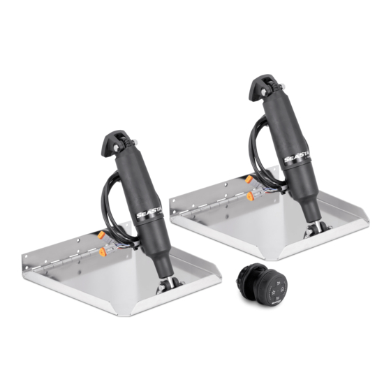
- Page 1 POWER & CONTROL ADAPTIVE TRIM TAB SYSTEM Optimus Adaptive Trim Tab System Adaptive Trim Tab System Installation and Setup manual [REVISION E] Form No. 682229 | ©2020 Dometic Corporation...
- Page 2 © 2020 Dometic Group. The visual appearance of the contents of this manual is protected by copyright and design law. The underlying technical design and the products contained herein may be protected by design, patent or be patent pending. The trademarks mentioned in this manual belong to Dometic Sweden AB unless otherwise noted.
-
Page 3: Table Of Contents
Adaptive Trim Tab System Installer: Please read this manual, and any other documentation included with this system, before attempting installation. This manual assumes you are familiar with the Adaptive Trim Tab System components and the information presented in the Operating Manual. All manuals included with this system must be delivered to the boat owner when installation is complete. -
Page 4: Explanation Of Symbols
Adaptive Trim Tab System Explanation of symbols WARNING! Safety instruction: Indicates a hazardous situation that, if not avoided, could result in death or serious injury. CAUTION! Safety instruction: Indicates a hazardous situation that, if not avoided, could result in minor or moderate injury. NOTICE! Indicates a situation that, if not avoided, can result in property damage. -
Page 5: Tab And Actuator Installation
Adaptive Trim Tab System Tab and actuator installation WARNING! • Read the instructions thoroughly before beginning the installation. • Before drilling holes in the hull, check that there is nothing in the hull that might be damaged, such as fuel or water tanks, electrical wiring, hydraulic steering hoses, etc. - Page 6 Adaptive Trim Tab System • There are different tab configurations available and they will have different transom height (TH) requirements as shown in figure . The actual transom height will vary with the angle of the transom, so the maximum value for TH is shown. Dimensions shown apply to standard 11.5”...
- Page 7 Adaptive Trim Tab System Tab installation — standard and edge mount tabs Position the tab (fig item 1) so that the hinge plate (fig item 2) is approxi- mately 1/4” (6mm) up from the bottom of the hull and parallel to the hull. See also figure If mounting in a pocket, center the tab in the pocket.
- Page 8 Adaptive Trim Tab System Liberally apply marine grade adhesive caulking (fig item 2) at the interface between the hinge and transom, the drilled holes, and the supplied fasteners (fig item 1) to ensure a watertight seal. Install the screws through the hinge plate and into the transom. The screws are designed to work in both fiberglass and aluminum hulls.
- Page 9 Adaptive Trim Tab System...
- Page 10 Adaptive Trim Tab System Ensure the actuator shaft (fig item 9) is fully retracted by rotating it clockwise until travel stops. The shaft can safely be forced to continue rotating clockwise to align the mounting holes at each end of the actuator. The actuator should come in this position out of the box, so adjustment may not be necessary.
- Page 11 Adaptive Trim Tab System Lift the tab into the running position as shown in figure . To ensure the tabs do not drag when retracted, they must be tilted up from the hull level. The longer the tab, the greater the height above the hull level at the trailing edge of the tab. You will need a long straight edge, such as a carpenter’s level, and a helper for this step.
- Page 12 Adaptive Trim Tab System Slide the mounting bracket (fig item 2) over the actuator harness (fig item 6) until you can mate it with the actuator (fig item 7). Fit pivot bolt (fig item 5) through the joint without installing thewasher and nut (fig item 8 and item 1).
- Page 13 Adaptive Trim Tab System Liberally apply marine grade sealant to the bracket, grommet, mounting holes and to the harness entry. Double check that there is a small amount of slack in the harness between the bracket and the entry into the actuator (fig item 2).
-
Page 14: Controller Installation
Adaptive Trim Tab System Controller installation The controller can be installed in a dash that is 1/4” to 1.5” thick and at any angle from horizontal to vertical. When determining where on the dash to place the trim tab controller, consider: •... - Page 15 Adaptive Trim Tab System .25" – 1.5" (6 mm – 38 mm) For installation of the controller into a location where pre-existing controller or rocker panel holes will still be visible, see “Trim Tab Cosmetic Controller Cover installation manual” (part # 682237).
-
Page 16: System Wiring
Adaptive Trim Tab System System wiring Planning the electrical installation is critical to a successful installation. Considering the electrical installation as a sequence of discrete steps can help organize your plan. Section 5.1, Step 1 – Plan the installation Section 5.2, Step 2 – Install the private CAN network Section 5.3, Step 3 –... - Page 17 Adaptive Trim Tab System Actuator power Review section 5.5. Before you begin installation, you should: • Know what power source you’re using. • Ensure the power source is suitable for the actuator power requirements. • Have a plan to extend the power source to the stern of the boat if necessary. •...
- Page 18 Adaptive Trim Tab System • The trunk, or backbone, is formed by tees connected linearly, either directly to each other or with harnesses (table 5-1). Each tee has two backbone connectors (male and female), and a female drop connector. • Drops are connections to devices on the network. •...
- Page 19 Adaptive Trim Tab System Important things to consider when building a CAN network: • Every network must have two – and only two – terminating resistors, one at each end of the backbone. One male and one female terminator are included in your installation kit.
- Page 20 Adaptive Trim Tab System ALL NUTS DOUBLE CHECKED FOR TIGHTNESS AND MARKED SCREWS IN ALL MOUNT HOLES EACH CABLE APPROPRIATELY SECURED AND STRAIN RELIEVED CLOSE TO TEES NO PULLING NOTE: TEES MAY NOT LOOK ON TEES EXACTLY AS SHOWN 5.2.3 Network installation —...
- Page 21 Adaptive Trim Tab System Installation: Mount a tee for each actuator and controller in your system. Review the requirements for the network power (page 21) and determine the best location for the network power tee. It may not be as shown in the diagrams. Connect the tees with harnesses to build the CAN network backbone.
- Page 22 Adaptive Trim Tab System MAIN STATION CONTROLLER NETWORK CM10060 TERMINATOR NETWORK TEES SECOND STATION NETWORK POWER CONTROLLER CM20043 3' COMMUNICATION HARNESS (x2) DEVICENET HARNESS 3 PIN DEUTSCH CONNECTOR (x2) (USER-INSTALLED) CM10003 3' HARNESS (LONGER LENGTHS AVAILABLE) 6' ACTUATOR HARNESS (x2) TRIM TAB ACTUATOR (x2)
- Page 23 Adaptive Trim Tab System Network power connection NOTE If the boat is equipped with Optimus EPS the control power will come from the CAN2 network and you may ignore this section. Network power turns the trim tab system on and off. The dial controller is powered directly from the network, and the actuators receive a wake-up signal when the network is powered on.
- Page 24 NOTE This section is for boats equipped with an Optimus EPS system. For other installations go to section 5.2.3. The Optimus Adaptive Trim Tab system uses the existing Optimus EPS CAN2 network as shown in figure (single controller) and figure (dual controller).
- Page 25 Adaptive Trim Tab System Installation: Mount a tee for each actuator and controller in your system. Run harnesses as required to connect the tees to the CAN2 network backbone. Route the harness(es) so they are dry, away from sources of heat, and properly secured.
- Page 26 Adaptive Trim Tab System SECOND STATION CONTROLLER NETWORK MAIN STATION CM10060 TERMINATOR NETWORK CONTROLLER TEES (x4) CM20043 3' COMM. HARNESS (x2) DEVICENET HARNESS OPTIMUS CAN2 NETWORK 3 PIN DEUTSCH CONNECTOR (x2) (USER-INSTALLED) CM10003 3' HARNESS (LONGER LENGTHS AVAILABLE) 6' ACTUATOR HARNESS (x2) TRIM TAB ACTUATOR (x2)
- Page 27 Adaptive Trim Tab System Step 3 — Install connectors on actuator harnesses The actuators come with a 6’ (1.8m) harness containing the five conductors listed in table 5-2. The conductors are fitted with crimped terminals, but the connectors must be installed after the harness has been routed into the boat and sealed. These connectors will mate with the power and communication harnesses that come with the actuator kit.
- Page 28 Adaptive Trim Tab System Repeat for all the contacts in the connector. When all the contacts are inserted, install the locking wedge from the pin side. Press it in firmly until you hear a click If the wire needs to be removed: Remove the wedge lock.
- Page 29 Adaptive Trim Tab System Step 4 — Connect devices to the private network 5.4.1 Dial controller The dial controller has two connectors on the back, labeled ‘CAN2’ and ‘N2K.’ The N2K port is shipped with a sealing cap; leave it in place unless you are connecting to a public network (section 5.6).
- Page 30 6' ACTUATOR HARNESS (x2) CM20044 3' POWER HARNESS (x2) 2 PIN DEUTSCH CONNECTOR (x2) (USER-INSTALLED) 20 AMP FUSES/ BREAKERS TRIM TAB ACTUATOR (x2) PORT STARBOARD 12V POWER 12V POWER SOURCE SOURCE COMPONENTS NOT SUPPLIED BY DOMETIC...
- Page 31 (USER-INSTALLED) 6' ACTUATOR HARNESS (x2) 3 PIN DEUTSCH CONNECTOR (x4) (USER-INSTALLED) CM20044 3' POWER HARNESS (x4) STARBOARD HD ACTUATOR (x2) PORT HD ACTUATOR (x2) 20 AMP FUSES/BREAKERS PORT STARBOARD 12V POWER 12V POWER SOURCE SOURCE COMPONENTS NOT SUPPLIED BY DOMETIC...
- Page 32 INSULATED STUD MIN. WIRE SIZE MIN. WIRE SIZE CONNECTORS PER TABLE 5-3 PER TABLE 5-3 7" (175 mm) 20 AMP FUSES/ MIN. WIRE SIZE BREAKERS PER TABLE 5-3 PORT 12V STARBOARD 12V POWER SOURCE POWER SOURCE COMPONENTS NOT SUPPLIED BY DOMETIC...
- Page 33 Adaptive Trim Tab System Use red wire of the size shown in table 5-3 to connect the breaker to the insulated stud connector. Take care to route and secure the wire properly. If there is no negative bus aft, install one and connect to the battery -ve with black or yellow wire of the size shown in table 5-3.
- Page 34 Adaptive Trim Tab System Boat has a NMEA2000-compliant network Add a tee to the existing public network. Remove the sealing cap from the port marked ‘N2K’ on the main station dial controller. Use a harness (table 5-1) to connect the dial controller N2K port to the tee. Secure the harness at both ends for strain relief.
-
Page 35: Setup
Adaptive Trim Tab System Setup The Adaptive Trim Tab System needs to be configured before use. Setup is done with a CANtrak display (section 6.1) or the dial controller (section 6.2). Setup with display NOTE If the boat is not equipped with a CANtrak display, you will need to add a temporary tee to the CAN network and connect a display tool to it. - Page 36 Adaptive Trim Tab System 6.1.2 Stroke limit In some applications you may need to limit the stroke of the actuators. The system provides several stroke lengths that can be configured, as shown in the table. Note that the stroke length affects extension, not retraction. The actuators will always retract to the home position—...
- Page 37 Adaptive Trim Tab System Setup with dial controller The function of the dial controller during setup is illustrated below. No. in Name in Function figure this section Favorite Saves the parameter and advances to the next step. Port LEDs Indicates the setup step, from 0 (no LEDs) to 8 (all LEDs). Dial Clockwise rotation increases the parameter, counterclockwise decreases it.
- Page 38 Adaptive Trim Tab System To enter setup mode: Key on the ignition. Simultaneously press and hold the Bow Down and Bow Up buttons for five seconds. ✓ The status LED will alternate blue and magenta. ✓ The port LEDs are all off, indicating that you are in step 0. 6.2.1 Step 0 —...
- Page 39 Adaptive Trim Tab System ✓ The actuator(s) you unplugged are instanced as starboard. The actuator(s) that remained plugged in are instanced as port. ✓ On HD installations with two actuators per tab, the lower serial number will be instanced as main, the other will be second. Press the Favorite button to save and continue to Step 1.
- Page 40 Adaptive Trim Tab System...
- Page 41 Optimus steering parameters, so you can import an entire configuration file into identical boat builds. • Settings parameters are advanced parameters. The default settings should work for most boats. You should not need to change them unless advised by a Dometic technical services representative.
- Page 42 Adaptive Trim Tab System Parameter Default Value Description Initial setup parameters, found at: Dealer Menu > Initial Setup > Adaptive Dial Controller > Holeshot Planing Boat 22 mph The minimum speed-over-ground (SOG) at which Speed the boat gets on plane under slow acceleration. This parameter is only used if a SOG source is available and the SOG feature is enabled (table 6-5).
- Page 43 Adaptive Trim Tab System Control and Options parameters There are parameters for trim control as well as optional feature settings. Parameter Default Value Description These parameters are found at: Dealer Menu > Settings > Adaptive Dial Controller > Control Pitch Control Controls the magnitude and speed of pitch adjust- Sensitivity ments (bow up/down).
-
Page 44: Testing And Commissioning
Adaptive Trim Tab System Testing and commissioning Once the system has been installed, and the sealant used on all hull penetrations has had time to fully cure (refer to the sealant manufacturer’s instructions), sea trial the boat to test the trim tab functions and to make any required adjustments to the system parameters. - Page 45 Adaptive Trim Tab System 2. Planing Boat Speed Note the speed at which the boat gets on plane and enter it in this parameter. 3. Deploy Position Activate Holeshot Mode and throttle up as you normally would when taking the boat up on plane.
- Page 46 Adaptive Trim Tab System Faults and troubleshooting 7.2.1 Fault types Non-critical faults A flashing yellow status LED indicates a fault that does not affect the actuators. An example is a faulty dial sensor. The trim tabs would still be operable using the bow up and bow down buttons, but the dial would not work.
- Page 47 LED is off. Circuit breaker or Reset breaker or replace fuse. fuse has tripped. The controller is not Optimus Adaptive Trim Tab System: receiving a wakeup if the CANtrak is on, check the signal. connections in the CAN2 network. If the CANtrak is not on, check the Optimus EPS ignition sensing wire.
- Page 48 Adaptive Trim Tab System The system status Tab(s) with blinking Check the harness connections LED is flashing red. position indicators for the affected actuator(s) and One or both tab are not making make sure they aren’t loose or position indicators position.
-
Page 49: Installation Template
Adaptive Trim Tab System Installation template .125" (3 mm) DIA. ANTI-ROTATION ANTI-ROTATION NOTCH AT TOP NOTCH AT TOP 1.375" (35 mm) OUTLINE OF 2.5" CONTROLLER (64 mm) 3.22" DIA. (82 mm) DIA. NOTE If this template has been downloaded electronically or copied from another document, please verify all template dimensions before use. - Page 50 Adaptive Trim Tab System This page left intentionally blank.
- Page 51 Notes _______________________________________________________________________________________________________________ _______________________________________________________________________________________________________________ _______________________________________________________________________________________________________________ _______________________________________________________________________________________________________________ _______________________________________________________________________________________________________________ _______________________________________________________________________________________________________________ _______________________________________________________________________________________________________________ _______________________________________________________________________________________________________________ _______________________________________________________________________________________________________________ _______________________________________________________________________________________________________________ _______________________________________________________________________________________________________________ _______________________________________________________________________________________________________________ _______________________________________________________________________________________________________________ _______________________________________________________________________________________________________________ _______________________________________________________________________________________________________________ _______________________________________________________________________________________________________________ _______________________________________________________________________________________________________________ _______________________________________________________________________________________________________________ _______________________________________________________________________________________________________________ _______________________________________________________________________________________________________________ _______________________________________________________________________________________________________________...
- Page 52 Mobile living made easy. DOMETIC VANCOUVER 3831 NO.6 ROAD RICHMOND, B.C. CANADA V6V 1P6 www.dometic.com © 2020 DOMETIC PRINTED IN THE USA 10/21 Please scan FORM NO. 682229 REV. E this QR code and watch our latest Boating Safety video.
Need help?
Do you have a question about the Optimus Adaptive Trim Tab System and is the answer not in the manual?
Questions and answers