Dometic Go Power! GP-SB-PWM-10 User Manual
10 & 30amp pwm solar controller
Hide thumbs
Also See for Go Power! GP-SB-PWM-10:
- User manual (26 pages) ,
- Quick start manual (2 pages)
Advertisement
Quick Links
10 & 30AMP PWM
SOLAR CONTROLLER
User Manual
GP-SB-PWM-10
GP-SB-PWM-30BT
© 2023 Go Power!
Worldwide Technical Support and Product Information
Go Power! | Dometic
201-710 Redbrick Street Victoria, BC, V8T 5J3
Tel: 1.866.247.6527
Manual_GP-SB-PWM - 10 30BT
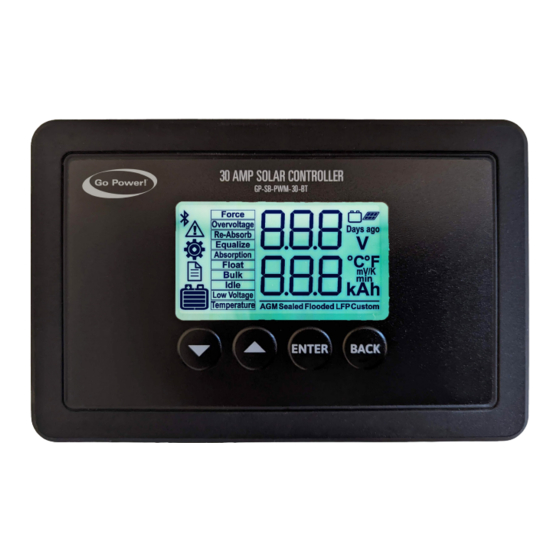
GP-SB-PWM-30BT MODEL SHOWN
gopowersolar.com
Advertisement

Subscribe to Our Youtube Channel
Related Manuals for Dometic Go Power! GP-SB-PWM-10


Summary of Contents for Dometic Go Power! GP-SB-PWM-10
- Page 1 10 & 30AMP PWM SOLAR CONTROLLER User Manual GP-SB-PWM-10 GP-SB-PWM-30BT GP-SB-PWM-30BT MODEL SHOWN © 2023 Go Power! Worldwide Technical Support and Product Information gopowersolar.com Go Power! | Dometic 201-710 Redbrick Street Victoria, BC, V8T 5J3 Tel: 1.866.247.6527 Manual_GP-SB-PWM - 10 30BT...
- Page 2 CONTENTS ABOUT THIS MANUAL .......................3 GENERAL SAFETY INFORMATION ....................3 SAFETY PRECAUTION ........................3 1. PRODUCT OVERVIEW ......................5 1.1 GENERAL DESCRIPTION ........................5 1.2 WHAT’S INCLUDED .........................5 1.3 COMPLIANCE INFORMATION ......................6 1.4 TECHNICAL SPECIFICATIONS ......................6 1.5 BATTERY CHARGING STAGES ......................7 2. PRE-INSTALLATION ......................8 2.1 CHOOSING AN INSTALLATION LOCATION ..................8 2.2 CHOOSING A BATTERY ........................8 2.3 INSTALLATION TOOLS NEEDED .......................8...
- Page 3 ABOUT THIS MANUAL Thank you for choosing Go Power! Solar Controller. This manual will provide you with all the information you need to properly install and use your solar controller. This manual contains important information about the safe installation and operation of the solar controller. Please keep this manual for future reference.
- Page 4 SAFETY PRECAUTION Observe all safety precautions of the battery manufacturer when handling or Warning: working around batteries. When charging, some batteries may produce hydrogen Battery and wiring safety gas, which is highly explosive. Ensure all connections are tight and secure to the specifications listed in section Warning: 6.
- Page 5 1. PRODUCT OVERVIEW Mandatory Action: This symbol indicates a prohibited action. The specific prohibited action is often Connections are Tightened indicated by this symbol. Never attempt the prohibited action. Mandatory Action: Prior to installing the controller, remove all connections between the controller Remove Connection and the battery or PV array, or disconnect the appropriate fuses/breakers.
- Page 6 PRODUCT OVERVIEW 1.3 COMPLIANCE INFORMATION COMPLIANCE CATEGORY COMPLIANCE LOGO COMPLIANCE REQUIREMENT RoHS EU RoHS Directive 2011/65/EU EU safety, health and environmental requirements UL 1741 Standard for Inverters, Converters, Controllers and Interconnection System Equipment for Use with Distributed Energy Resources UL 1471 CU 72181157 Photovoltaic charge controller Certified to UL1741, C22.2 No.
- Page 7 PRODUCT OVERVIEW 1.5 BATTERY CHARGING STAGES The charge controller has a 4-stage battery charging algorithm for a rapid, efficient, and safe battery charging. These stages include: Bulk, Absorption, Float, and Equalization. Visit gopowersolar.com/controllers to learn more about charging algorithms. 1.5.1 FIRST STAGE: BULK This algorithm uses 100% of available solar power to recharge the battery and provides the maximum current available based on maximum input current setting.
- Page 8 2. PRE-INSTALLATION 2.1 CHOOSING AN INSTALLATION LOCATION The GP-SB-PWM is designed to be mounted flush against a wall, out of the way but easily visible. The GP-SB-PWM should be: • Indoors, protected from the weather • Mounted as close to the battery as possible •...
- Page 9 INSTALLATION INSTRUCTIONS Wire Strip Length Strip wires to a length of approximately 3/8in or 10mm, as per strip gauge. IMPORTANT: Identify the polarity (positive and negative) on the cable used for the battery and solar module. Use colored wires or mark the wire ends with tags indicating “Solar Positive and Negative (+ / -)”. Although the GP-SB-PWM is protected, reverse polarity contact may damage the unit.
- Page 10 INSTALLATION INSTRUCTIONS 3.1 WIRING DIAGRAM The GP-SB-PWM Maximum 37.5A rating is based on a 30-amp total maximum short circuit current rating (Isc) from the parallel solar panels nameplate ratings. The National Electric Code specifies the PV equipment/system rating to be 125% of the maximum Isc from the solar panels nameplate ratings (1.25 times 30 = 37.5A).
- Page 11 INSTALLATION INSTRUCTIONS 3.2 BATTERY SET-UP 3.2.1 LEAD ACID BATTERY To setup a lead acid battery, hold the ENTER key and use the up ▲ and down ▼ keys to get to the setting’s options (cog icon Press ENTER. Battery type will be displayed. Press ENTER again and use the up ▲...
- Page 12 4. OPERATION If a battery is still not detected after the fifth trial, the controller shows error number 32 to indicate this failure. The controller gives up until it is either manually reset by disconnecting and reconnecting solar power. The solar controller will not engage in this process if a new day is detected through the solar panel(s).
- Page 13 OPERATION 4.2 MENU OPERATION Three menus are implemented in the display: status, settings, and history. At power up, the controller turns on within the status menu. The different menus can then be accessed by pressing the Enter key as shown below. This leads to the status menu number one.
- Page 14 OPERATION 4.3 STATUS PARAMETERS The status menu is entered by the controller at power-up. It is used to display key parameters as well as warnings and faults. Three displays are automatically scrolled through as shown below. The up ▲ and down ▼ eys can also be used to manually scroll through these.
- Page 15 OPERATION When a fault or warning is present in the system, auto-scroll is disabled and the display freezes on the fault shown. These are displayed below: FAILURE TYPE DISPLAY Internal Temperature Circuit The internal temperature of the control unit (MCU) is too high.
- Page 16 OPERATION Battery Over Voltage The battery voltage is too high (if using a custom battery type, the setting in menu 9 sets this point). User should disconnect the battery and make sure it is rated for a 12V nominal system. If yes, contact the battery manufacturer for recommended next steps.
- Page 17 OPERATION SETTING TYPE DISPLAY 1. Battery Type (AGM / Sealed / Flooded / LFP (LiFePO4) / Custom) This is the type of battery that is connected to the solar controller. Set this so the solar controller charges the battery according to the needs of that battery 2.
- Page 18 OPERATION 8. History Reset (YES / NO) This resets the historical information in the solar controller. Use this if you want to start collecting data from a known point in time. 9. Battery Overvoltage Setpoint (8.0 to 16.0) This setpoint will show a fault if the battery voltage is higher than the 8.0 to 16.0 value.
- Page 19 OPERATION 15. Low Voltage Delay in seconds (0 to 120) The amount of time the controller will wait after the battery voltage falls below the low voltage setpoint before it indicates a fault. Use this to set the value ac- cording to system requirements if using the custom battery profile.
- Page 20 OPERATION 4.4 HISTORICAL PARAMETERS The GP-SB-PWM historical amp-hour charging can be accessed by entering menu number 3. This section allows the user to review the previous usage for different settings based on the selected timeframes, as explained on the following pages. These calculations do not reflect the entirety of the power generation of the solar panel(s), but the power put back into the battery Note to maintain the state of charge.
- Page 21 OPERATION HISTORY TYPE DISPLAY 5. Amp Hours in last 7 days Indicates how much power the controller has provided to the batteries from the solar panels 7 days previous. 6. Total Cumulative Amp Hours The total amount of power the controller has provided to the batteries since the last time the history was cleared using the clear history setting in the settings menu.
- Page 22 OPERATION 4.6.1 PAIRING When connecting for the first time, pairing between the charge controller and the mobile device is required. Also ensure your mobile device’s Blue- tooth® communication function is enabled. You will see the Bluetooth symbol present on your status bar if so. Open the app, and the Main page ®...
- Page 23 OPERATION Please disconnect from the controller when you are done using the app. This helps mitigate any future connection issues. To disconnect the controller, press the “Go Power” Logo located at the top left of the app and click the red DISCONNECT button. The same button is found at the bottom of the Status page.
- Page 24 5. MAINTENANCE Maintaining your solar charge controller is essential to ensure it operates efficiently and effectively. We recommend following these maintenance protocols once every six (6) months: • Inspecting the controller: Check the charge controller regularly to see if it’s in good condition. Inspect the wires, terminals, and other parts for damage or wear.
- Page 25 TROUBLESHOOTING 6.2 PROBLEMS WITH VOLTAGE Voltage Reading: Inaccurate Time of Day: Daytime/Nighttime Possible Causes: Excessive voltage drop from batteries to controller due to loose connections, small wire gauge or both. How to tell: Check the voltage at the controller battery terminals with a voltmeter and compare with the voltage reading at the battery terminals. If there is a voltage discrepancy of more than 0.5 V, there is an excessive voltage drop.
- Page 26 TROUBLESHOOTING Disconnect one or both array wires from the controller. Take a voltage reading between the positive and negative array wire. A single 12 volt module should have an open circuit voltage between 17 and 22 volts. If you have more than one solar module, you will need to conduct this test between the positive and negative terminals of each module junction box with either the positive or the negative wires disconnected from the terminal.
- Page 27 8. APPENDIX 8.1 MOUNTING TEMPLATE 2.96in 3.87in 75.1mm 98.2mm 5.2in 132.5mm 5.90in 149.9mm gopowersolar.com | [page 27]...
- Page 28 © 2023 Go Power! Worldwide Technical Support and Product Information gpelectric.com Go Power! | Dometic 201-710 Redbrick Street Victoria, BC, V8T 5J3 Tel: 1.866.247.6527 Manual_GP-SB-PWM - 10 30BT gopowersolar.com | [page 28]...
Need help?
Do you have a question about the Go Power! GP-SB-PWM-10 and is the answer not in the manual?
Questions and answers