Table of Contents
Advertisement
Quick Links
Advertisement
Table of Contents

Subscribe to Our Youtube Channel
Related Manuals for Dometic Go Power! 30 AMP RVC MPPT


Summary of Contents for Dometic Go Power! 30 AMP RVC MPPT
- Page 1 30 AMP RVC MPPT SOLAR CONTROLLER User Manual GP-RVC-30-MPPT © 2021 Go Power! Worldwide Technical Support and Product Information gpelectric.com Go Power! | Dometic 201-710 Redbrick Street Victoria, BC, V8T 5J3 Tel: 1.866.247.6527 MAN_GP-RVC-30-MPPT_RevA...
- Page 2 Congratulations on purchasing your Go Power! GP-RVC-30-MPPT Solar Controller! Record the unit’s model and serial number below. It is much easier and quicker to record this information now at the pre-installation stage. Model Number: Serial Number: Date of Install: Battery Bank Information: (size, install date, battery type) Product Packaging Please safely store the packing the product was delivered in or recycle the packaging components as outlined below:...
-
Page 3: Table Of Contents
CONTENTS 1. SAFETY ......................4 2. INTRODUCTION ....................5 3. APPERANCE .....................6 4. MAXIMUM POWER POINT TECHNOLOGY ............7 5. CHARGING STAGES ..................9 6. DUAL BATTERY CHARGING ................11 7. PRODUCT DIMENSIONS ..................12 8. SPECIFICATIONS .....................13 9. LED INDICATORS ....................14 10. INSTALLATION ....................15 11. RV-C INSTANCE NUMBER ................17 12. -
Page 4: Safety
1. SAFETY Important safety information is contained throughout this manual that should be carefully observed and followed. This information is presented using the following format: Warning / Caution: Result Description of condition leading to result SYMBOL information is categorized in two ways: Warning: Bodily harm could occur if instructions are not explicitly followed. -
Page 5: Introduction
2. INTRODUCTION 2.1 OVERVIEW The 30A RV-C MPPT solar controller is an advanced dual bank controller with RV-C communication for smart RV systems. As an MPPT Solar controller it continuously monitors the solar panel’s generating power and tracks the maximum power point, enabling the system to charge the battery with maximum power all the time. -
Page 6: Apperance
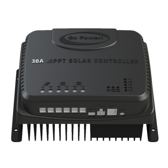
3. APPEARANCE NAME NAME Instance Indicators Connection Terminals (PV-) LED Indicator (BAT2) Connection Terminals (PV+) LED Indicator (BAT1) Port for external temperature sensor LED Indicator (PV) Canbus Communication Port Connection Terminals (BAT2-) RS485 Communication Port Connection Terminals (BAT2+) Setup Key Connection Terminals (BAT1-) Installation Hole Connection Terminals (BAT1+) -
Page 7: Maximum Power Point Technology
4. MAXIMUM POWER POINT TECHNOLOGY Maximum Power Point Tracking (MPPT) is an advanced charging technology that more efficiently harvests power from solar panels in all conditions. It does this by continuously tracking the I-V curve of the solar array and modifying operating conditions to maximize output power. - Page 8 MAXIMUM POWER POINT TECHNOLOGY The graph below shows how the IV curve of a solar panel changes with varying temperatures. In partially shaded conditions there can also be multiple peaks in the P-V curve that can confuse an MPPT algorithm. Shown in the diagram below is a series string of solar panels.
-
Page 9: Charging Stages
5. CHARGING STAGES Maximum power point tracking is used to charge the batteries with the highest current possible, but this is only part of the equation. A battery cannot be charged at maximum power all the time for safety reasons, so multiple stages are used. These stages include: bulk, absorption, float and, for some types of batteries, equalization as indicated below. - Page 10 CHARGING STAGES STAGE 4: EQUALIZE Warning: Risk of explosion! Equalizing vented lead-acid battery may generate explosive gases. So, the battery compartment must be well ventilated. Caution: Damage of device! Equalization can increase the battery voltage to levels that may damage sensitive DC loads. It is necessary to verify that the allowable input voltage of all system loads is greater than the equalizing charge set value.
-
Page 11: Dual Battery Charging
6. DUAL BATTERY CHARGING The GP-RVC-30-MPPT has two battery outputs: BAT1 and BAT2. The solar controller will prioritize BAT1 at all times to ensure it is always charged as much as possible. After BAT1 has completed absorption charging excess power will be used to charge BAT2. -
Page 12: Product Dimensions
7. PRODUCT DIMENSIONS [page 12] | gpelectric.com... -
Page 13: Specifications
8. SPECIFICATIONS ITEM PARAMETERS Battery Voltage Range 8V – 32V Max Charge Current Conversion Efficiency ≤98% MPPT Tracking Efficiency >99% Max Panel Input Voltage 100Voc Max PV Power Input 600W@12V / 1200W@24V No-Load Loss <10mA Grounding Negative Operating Temperature -35 to 45°C Storage Temperature -35 to 75°C Humidity... -
Page 14: Led Indicators
9. LED INDICATORS 9.1 LED IDENTIFICATION 9.2 PV INDICATOR LED PATTERN STATUS Night time Single flash Day time Steady On MPPT charging Fast Flash Absorption or Equalize Slow Flash Float Charging 9.3 BATTERY INDICATOR LED PATTERN STATUS No Battery Fast Flash Battery over voltage Slow Flash Battery over discharged... -
Page 15: Installation
10. INSTALLATION 10.1 TOOLS AND MATERIALS NEEDED • Screwdriver • Drill • Multimeter 10.2 INSTALLATION AND WIRING STEP 1: CHOOSE AN INSTALLATION LOCATION The following things should be considered when choosing an installation location for GP-RVC-30-MPPT controllers. • The controller should be installed indoors where it is safe from water or condensation •... - Page 16 INSTALLATION STEP 4: WIRING Wiring and installation must comply with national and local electrical code requirements. The wire from the solar array most commonly enters the RV through the fridge vent on the roof or by using the Go Power! Cable Entry Plate (sold separately) that allows installers to run wires through any part of the roof.
-
Page 17: Rv-C Instance Number
11. RV-C INSTANCE NUMBER 11.1 RV-C INSTANCE NUMBER IDENTIFICATION The RV-C instance of an individual controller can be identified by the 5 LEDs on the controller shown below. 11.1 CHANGING THE RV-C INSTANCE NUMBER The instance of the solar controller on the RV-C network can be configured using the SET button and LEDs. Up to 5 unique instances are supported. -
Page 18: Rv-C Remote
12. RV-C REMOTE Bluetooth Enabled GP-RVC-R Remote ® Conveniently set and view essential charge information. The GP-RVC-R is a surface mounted remote display for GP-RVC-MPPT photovoltaic (PV) charge controllers. The GP-RVC-R shows the charge current to the battery and battery voltage. •... -
Page 19: Limited Warranty
13.LIMITED WARRANTY Go Power! warrants the GP-RVC-R for a period of five (5) years from the date of shipment from its factory. This warranty is valid against defects in materials and workmanship for the five (5) year warranty period. It is not valid against defects resulting from, but not limited to: •... - Page 20 © 2021 Go Power! Worldwide Technical Support and Product Information gpelectric.com Go Power! | Dometic 201-710 Redbrick Street Victoria, BC, V8T 5J3 Tel: 1.866.247.6527 MAN_GP-RVC-30-MPPT_RevA...
Need help?
Do you have a question about the Go Power! 30 AMP RVC MPPT and is the answer not in the manual?
Questions and answers