Dometic Go Power! GP-SB-PWM-10 User Manual
10 & 30amp pwm solar controller
Hide thumbs
Also See for Go Power! GP-SB-PWM-10:
- Quick start manual (2 pages) ,
- User manual (28 pages)
Table of Contents
Advertisement
10 & 30AMP PWM
SOLAR CONTROLLER
User Manual
GP-SB-PWM-10
GP-SB-PWM-30BT
30AMP CONTROLLER SHOWN. BLUETOOTH
© 2022 Go Power!
Worldwide Technical Support and Product Information
Go Power! | Dometic
201-710 Redbrick Street Victoria, BC, V8T 5J3
Tel: 1.866.247.6527
Manual_GP-SB-PWM - 10 30BT
FEATURE AVAILABLE ON THE 30A SOLAR CONTROLLER ONLY.
®
gpelectric.com
Advertisement
Table of Contents

Related Manuals for Dometic Go Power! GP-SB-PWM-10


Summary of Contents for Dometic Go Power! GP-SB-PWM-10
- Page 1 30AMP CONTROLLER SHOWN. BLUETOOTH FEATURE AVAILABLE ON THE 30A SOLAR CONTROLLER ONLY. ® © 2022 Go Power! Worldwide Technical Support and Product Information gpelectric.com Go Power! | Dometic 201-710 Redbrick Street Victoria, BC, V8T 5J3 Tel: 1.866.247.6527 Manual_GP-SB-PWM - 10 30BT...
-
Page 3: Table Of Contents
CONTENTS 1. INTRODUCTION .........................4 1.1 INTRODUCTION ..........................4 1.2 SYSTEM VOLTAGE AND CURRENT ....................4 1.3 BATTERY TYPE ..........................4 1.4 REGULATORY INFORMATION ......................4 1.5 SPECIFICATIONS ..........................5 2. WARNINGS ........................6 3. TOOLS AND MATERIALS NEEDED ..................7 4. CHOOSING A LOCATION .....................7 5. CHOOSING A BATTERY .......................7 INSTALLATION INSTRUCTIONS ...................... -
Page 4: Introduction
1. INTRODUCTION 1.1 INTRODUCTION A Solar Controller (or Charge Controller / Regulator) is an essential component of your photovoltaic solar system. The Controller maintains the life of the battery by protecting it from overcharging. When your battery has reached a 100% state of charge, the Controller prevents overcharging by limiting the current flowing into the batteries from your solar array. -
Page 5: Specifications
INTRODUCTION 1.5 SPECIFICATIONS DESCRIPTION GP-SB-PWM-10 GP-SB-PWM-30-BT Nominal System Voltage Dimensions (H x W x D): Nominal Charge Current 125.2 x 73.5 x 27 mm Range of Battery Input Voltage 6 – 16 V 4.93 x 2.89 x 1.09 in Max Battery Charge Current 12.5A 37.5A Weight: 260 g / 9.2 oz... -
Page 6: Warnings
2. WARNINGS Electricity can be very dangerous. Installation should be performed only Disconnect all power sources by a licensed electrician or qualified personnel. Observe all safety precautions of the battery manufacturer when handling Battery and wiring safety or working around batteries. When charging, batteries produce hydrogen gas, which is highly explosive. -
Page 7: Tools And Materials Needed
3. TOOL AND MATERIALS NEEDED • Flathead Screwdriver (for wire terminals) • Philips Screwdriver (for mounting screws) If the GP-SB-PWM Controller was purchased with a Go Power! RV Solar Power Kit, then UV resistant wire is included. Note For instructions regarding the Go Power! RV Solar Power Kit installation, please refer to the Installation Guide provided with the Kit. - Page 8 INSTALLATION INSTRUCTIONS Suggested Minimum Wire Gauge (Cable length 25 ft. max. from solar array to battery bank) 55 Watt Solar Module #14 Wire Gauge 80 Watt Solar Module #12 Wire Gauge 100 Watt Solar Module #10 Wire Gauge 110 Watt Solar Module #10 Wire Gauge 200 Watt Solar Module #10 Wire Gauge...
-
Page 9: Wiring Diagram
7. WIRING DIAGRAM The GP-SB-PWM Maximum 37.5A rating is based on a 30-amp total maximum short circuit current rating (Isc) from the parallel solar modules’ nameplate ratings. The National Electric Code specifies the PV equipment/system rating to be 125% of the maximum Isc from the PV module nameplate ratings (1.25 times 30 = 37.5A). -
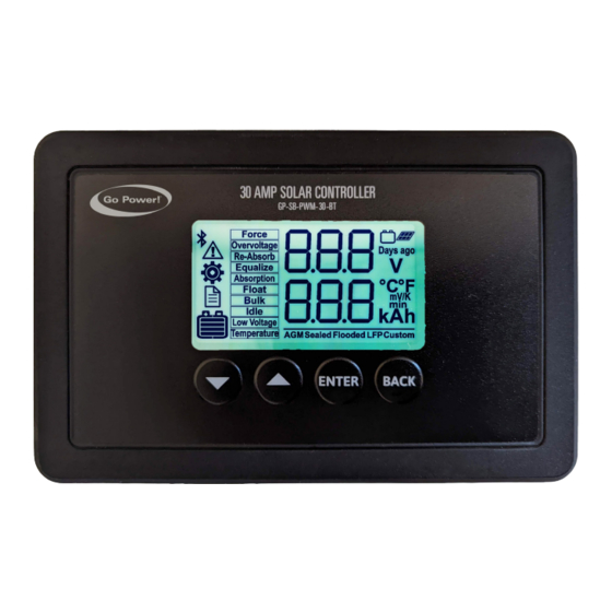
Page 10: Menu Operation
OPERATING INSTRUCTIONS 8.1 MENU OPERATION Three menus are implemented in the display: status, settings, and history. At power up, the controller turns on within the status menu. The different menus can then be accessed by pressing the Enter key as shown below. This leads to the status menu number one. -
Page 11: Charging Algorithm
9. CHARGING ALGORITHM The charge controller has a 4-stage battery charging algorithm for a rapid, efficient, and safe battery charging. These stages include: Bulk, Absorption, Float, and Equalization. 9.1 FIRST STAGE: BULK This algorithm uses 100% of available PV power to recharge the battery and provides the maximum current available based on max- imum input current setting. -
Page 12: Lithium Wake-Up
10. LITHIUM WAKE-UP When the GP-SB-PWM is powered by a PV panel but the battery is not detected, it sends 5 pulses to restore a Lithium battery that has been protected from over discharge by its BMS. The LCD indicates this process by showing the displays below. If a battery is still not detected after the fifth trial, the controller shows error number 32 to ndicate this failure. -
Page 13: Status Parameters
12. STATUS PARAMETERS The status menu, entered by the controller at power-up, is used to display key parameters as well as warnings and faults.Three displays are automatically scrolled through as shown below. The up and down keys can also be used to manually scroll through these. - Page 14 STATUS PARAMETERS When a fault or warning is present in the system, auto-scroll is disabled and the display freezes on the fault shown. These are displayed below: FAILURE TYPE DISPLAY Internal Temperature Circuit Battery Voltage Reverse Polarity PV Voltage Reverse Polarity PCB Over Temperature PV Over Voltage LFP Wake Up...
-
Page 15: Settings Parameters
13. SETTINGS PARAMETERS Battery Over Voltage Charge Temperature Limits Violation 13. SETTINGS PARAMETERS The GP-SB-PWM settings can be accessed by entering menu number 2 as shown below. Settings number 9 to 19 are only relevant to the custom battery type and will only be visible if the battery type setting number 1 is set to Custom. SETTING TYPE DISPLAY Battery Type... - Page 16 SETTINGS PARAMETERS Force Absorption (yes / no) Enable / Disable Charging (EnA / diS) Enable / Disable Status Rotation (EnA / diS) Soft Reset (yes / no) Factory Reset (yes / no) History Reset (yes / no) Battery Overvoltage Setpoint (8.0 to 16.0) [page 16] | gpelectric.com...
- Page 17 SETTINGS PARAMETERS Equalization Voltage Setpoint (8.0 to 16.0) Absorption Voltage Setpoint (8.0 to 16.0) Float Voltage Setpoint (8.0 to 16.0) Re-Absorb Voltage Setpoint (8.0 to 16.0) Low Voltage Setpoint (8.0 to 16.0) Low Voltage Delay in seconds (0 to 120) Equalization Time in minutes (0 to 600) gpelectric.com | [page 17]...
-
Page 18: History Parameters
14. HISTORY PARAMETERS Absorption Time in minutes (0 to 600) Equalization Interval in days (0 to 225) Temperature Compensation (0 to 30) Firmware Version 14. HISTORY PARAMETERS The GP-SB-PWM historical amp-hour charging can be accessed by entering menu number 3. This includes various history data as shown on the following page. - Page 19 HISTORY PARAMETERS HISTORY TYPE DISPLAY Amp Hours from Today Amp Hours Yesterday Amp Hours 2 days ago Amp Hours 3 days ago Amp Hours in last 7 days Total Cumulative Amp Hours Operating Days gpelectric.com | [page 19]...
-
Page 20: Bluetooth ® Wireless Technology
15. BLUETOOTH WIRELESS TECHNOLOGY ® This section is for the GP-SB-PWM-30-BT Controller only! Note The GP-SB-PWM-30BT comes with Bluetooth Low Energy wireless technology for live status monitoring and settings configuration on mobile devices. ® It works together with the Go Power! Connect App, available for both Android and iOS devices. Download and install the Go Power! Connect app, which is available on the Google Play store for Android devices and the App Store for iOS devices. -
Page 21: App Usage
BLUETOOTH WIRELESS TECHNOLOGY ® 15.2 APP USAGE Upon initial connection you will load into the charge controller’s main status screen. You will be able to see the SoC, Battery Type, Voltage, Current of the controller. In addition to the main screen, there are two additional tabs “History & Alerts” to track the Ah usage and any important faults/alerts that may occur. -
Page 22: App Settings
15.3 APP SETTINGS In the App settings you will be able to set the battery type the solar controller is charging. The following batteries are supported below: In addition to the charge controller settings, you will be able to set the temperature unit, reboot, force float & absorption and reset the “Ah”... -
Page 23: Limited Warranty
16. LIMITED WARRANTY Go Power! warrants the GP-SB-PWM-30BT for a period of five (5) years from the date of shipment from its factory. This warranty is valid against defects in materials and workmanship for the five(5) year warranty period. It is not valid against defects resulting from, but not limited to: •... - Page 24 [page 24] | gpelectric.com...
-
Page 25: Mounting Template
17. MOUNTING TEMPLATE 2.96in 3.87in 75.1mm 98.2mm 5.2in 132.5mm 5.90in 149.9mm gpelectric.com | [page 25]... - Page 26 © 2022 Go Power! Worldwide Technical Support and Product Information gpelectric.com Go Power! | Dometic 201-710 Redbrick Street Victoria, BC, V8T 5J3 Tel: 1.866.247.6527 Manual_GP-SB-PWM - 10 30BT...
Need help?
Do you have a question about the Go Power! GP-SB-PWM-10 and is the answer not in the manual?
Questions and answers
When to the toggle switch on or off