Table of Contents
Advertisement
Quick Links
Basic Chiller Control
Operations Manual
Dometic Group Marine Division
Rev. 20180709
L‐3527 English
P/N 338238
COPYRIGHT © 2011‐2018 Dometic Group Marine Division. All Rights Reserved.
No part of this publication may be reproduced, translated, stored in a retrieval system, or transmitted in any form or by any means electronic,
mechanical, photocopying, recording or otherwise without prior written consent by Dometic Marine. Every precaution has been taken in the
preparation of this manual to insure its accuracy. However, Dometic Marine assumes no responsibility for errors and omission. Neither is any
liability assumed for damages resulting from the use of this product and information contained herein.
Advertisement
Table of Contents

Subscribe to Our Youtube Channel
Related Manuals for Dometic SmartStart III


Summary of Contents for Dometic SmartStart III
- Page 1 Basic Chiller Control Operations Manual Dometic Group Marine Division Rev. 20180709 L‐3527 English P/N 338238 COPYRIGHT © 2011‐2018 Dometic Group Marine Division. All Rights Reserved. No part of this publication may be reproduced, translated, stored in a retrieval system, or transmitted in any form or by any means electronic, mechanical, photocopying, recording or otherwise without prior written consent by Dometic Marine. Every precaution has been taken in the preparation of this manual to insure its accuracy. However, Dometic Marine assumes no responsibility for errors and omission. Neither is any liability assumed for damages resulting from the use of this product and information contained herein. ...
-
Page 2: Table Of Contents
Table of Contents INTRODUCTION . . . . . . . . . . . . . . . . . . . . . . . . . . . . . . . 3 SYSTEM OVERVIEW . . . . . . . . . . . . . . . . . . . . . . . . . . . 6 ‐ . . . . . . . . . . . . . . . . . . . . . . . . . . 6 YSTEM OWER UP PGD1 NAVIGATION . . . . . . . . . . . . . . . . . . . . . . . . . . . . 3 . . . . . . . . . . . . . . . . . . . . . . 6 OFTWARE REVISION TOUCHSCREEN NAVIGATION . . . . . . . . . . . . . . . . . . . 2 . . . . . . . . . . . . . . . . . . . . . . . . . . . . . . . . . . 6 TARTUP . . . . . . . . . . . . . . . . . . . . . . . . . . .. . . . . . 2 AIN AGE . . . . . . . . . . . . . . . . . . . . . . . . 6 PERATIONAL HECKS . . . . . . . . . . . . . . . . . . . .. . . . . 2 HILLER NABLE . . . . . . . . . . . . . . . . . . . . . . . . . . . . . . . . . 6 ETPOINTS . . . . . . . . . . . . . . .. . . . . . . . . 2 HILLER ... -
Page 3: Introduction
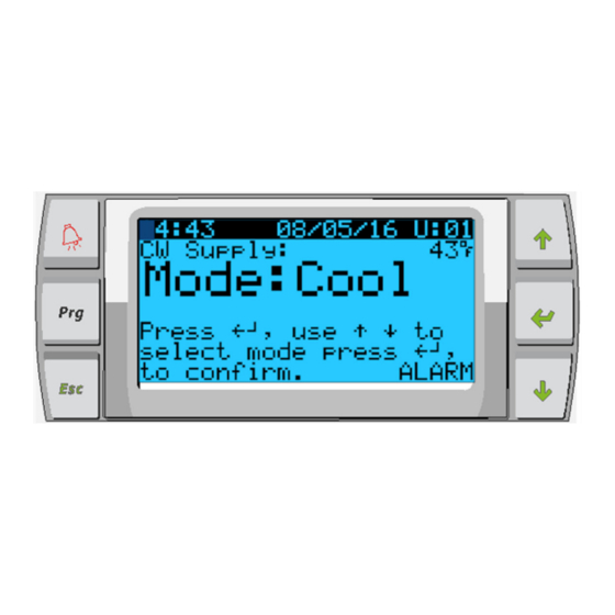
INTRODUCTION The Dometic PLC controls is a microcontroller‐based unit designed to control multiple chillers. This design allows the user flexibility in the application and improved controls and protection. The PLC Chiller uses temperature differential and hysteresis to manage the capacity of the chiller in single or multistage application. This application supports the following: Selection and sequencing of up to six chillers Selection and sequencing of one chill water pump and one sea water pump Selection and sequencing of up to 6 EH heaters Sequencing of devices for runtime equalization Alarms and interlocks Troubleshooting help The main interface supported will be the LCD display, referred to as the PGD1 display. Figure 1: PGD1 Button Description Alarm Indicator Scroll Up Program Mode Enter Escape to Exit Scroll Down PGD1 NAVIGATION Enter Button The PGD1 controller screen will automatically boot up to the Main screen. This screen allows you to enable or disable the chiller by ... -
Page 4: General Information
Alarm Button This button will flash red if there is an active alarm. Pressing this button will take you to the active alarm screen to display the alarm. Once in the alarm screen, use the up/down buttons to scroll through alarms. The Alarm screen captures a snapshot of the system parameters at the time of the fault. Press and hold the Alarm button for 3 seconds to clear the active alarm if the fault has been corrected. GENERAL INFORMATION The Dometic PLC controls is a microcontroller‐based unit designed to control multiple chillers. This design allows the user flexibility in the application and improved controls and protection. The PLC Chiller uses temperature differential and hysteresis to manage the capacity of the chiller in single or multistage application. The chiller system will come programmed from the factory with the options enabled for that system. Although the system offers flexibility, these options can only be enabled by a factory representative. The user will be able to select between Cool, Heat or Electric Heat mode operation in single stage configuration or In a multistage configuration. The PLC controller is internally grounded with isolation between inputs and outputs. Additionally, the output relays offer double isolation so that different voltages can be used for groups of relays. The system will utilize various sensor types for measuring analog temperatures and pressures. For temperature measurements, the system will use NTC type 10K@77° thermistors. Pressure transducers are ratiometric 0‐650 PSI (45 bar) range for both suction and discharge monitoring. Available Options: 1. Compressor Current Monitoring 2. Pump Current Monitoring (SW and CW) 3. Condenser Freeze Protection 4. Electric Heat 5. EEV Control 6. Pressure Transducers 7. Load Shedding Input Signal 8. Low Current Alarm to indicate if system is not actually running when enabled. (Pumps and Compressor) ... -
Page 5: Refrigerant Low - Low
REFRIGERANT LOW – LOW SIDE PRESSURE LIMIT (Optional) The PLC will immediately acknowledge an open circuit if the low pressure switch is tripped and de‐energize the compressor. It will record and display low pressure fault on the alarm screen. If the PLC detects a low pressure fault during operation, a LP fault will be displayed and recorded. The PLC will not allow the compressor relay to be re‐energized, until switch is in the closed position. The fault must be manually acknowledged via the PLC and cleared prior to re‐enabling the system or stage. ANALOG INPUTS HIGH LIMIT TEMPERATURE SETPOINT The high limit temperature sensor is continuously monitored whether in Cooling, Reverse Cycle or Electric Heat mode. This sensor is used to detect a high temperature condition in the supply water from the chiller. If the chilled water temperature is sensed to be greater or equal to 125°F (51.7°C), all enabled compressor relays will be de‐energized, turning off the compressor(s) if operating in reverse cycle mode. If electric heat is being used, all enabled heater relays will be de‐energized, turning off the heating element(s). As the temperature falls, the compressor or electric heat relay will re‐energize when the temperature reaches 110°F (43.3°C). A high temperature fault will be recorded and displayed if the system exceeds the alarm set point. In a high temperature situation, PLC will not allow the compressor or electric heat relay to be energized. The fault must be manually acknowledged on the active alarm screen and cleared prior to re‐enabling the system or stage. If a temperature sensor is bad or not connected, the PLC will display an alarm for that sensor. FREEZE TEMPERATURE SETPOINT The low limit temperature sensor is continuously monitored whether in Cooling, Reverse Cycle or Electric Heat mode. This sensor is used to detect a freeze condition in the supply water of the chiller. If the chilled water temperature is sensed to be equal to or less than 38°F (3.3°C), then the compressor relay will be de‐energized, shutting off the compressor. As the temperature rises, the compressor relay will re‐energize when the temperature reaches 42°F (5.6°C). ... -
Page 6: Relay Outputs
RELAY OUTPUTS COMP – COMPRESSOR PLC COMP output will provide switched power to the contactor coil to enable the compressor normal operation. CWP – CHILL WATER PUMP PLC CWP output will provide switched power to the contactor coils for the chilled water pump. SWP – SEA WATER PUMP PLC SWP output will provide switched power to the contactor coils for the sea water pump. RV – REVERSING VALVE PLC RV output will provide switched power to the coils for the reversing valve. EH – ELECTRIC HEAT PLC EH output will provide switched power to the contactor coils for the electric heat. FAULT Provides a Normally Open (NO) contact point. Any fault condition will close the NO contact. This output can be used to power a light, relay, or interface to a ship’s monitoring system. The output on this terminal will be 230 VAC. SYSTEM OVERVIEW SYSTEM POWER‐UP SOFTWARE REVISION Upon applying power to the system, the display will indicate the software revision number or display it on the main status screen. PLC is enabled and waiting for user selection. ... -
Page 7: Heating
EATING Heating set‐point is an adjustable parameter from 95°F (35°C) to 120°F (49°C) in one degree increments, for both Return & Supply control. To adjust the heating set point, simply touch the PLC screen and change to desired new set point. In heating mode you will not be able to enter a number outside of this range. OMPRESSOR TAGING IME Compressor staging time is a PLC adjustable parameter from 10 seconds to 110 seconds in 10‐second increments. To adjust the staging time, simply touch the PLC screen and change to desired new set point. User will not be able to enter a number outside of this range. Once the PLC initiates a cooling cycle, the staging time is the time it will take (in seconds) for the next compressor relay to close. RUN MODE – COOLING Compressor rotation is active during run mode. The compressor with the lowest running hours will be enabled first and compressor with the highest running hours will be disabled first. First stage will be enabled and the compressor will start after CW and SW flows are stable for 10 seconds (default). First stage will continue to run for 1 minute before enabling the next stage. If the loop requires demand, then the next stage will be enabled. – R UN ODE EVERSE YCLE EATING Compressor rotation is active during run mode. The compressor with the lowest running hours will be enabled first and compressor with the highest running hours will be disabled first. Enable Reverse Cycle Heat only for the system. First stage heating will be enabled and the compressor will start after CW and SW flows are stable for 10 seconds. First stage will continue to run for 5 minutes before enabling the next heater stage. If the loop requires demand, then the next stage will be enabled. – E UN ... -
Page 8: Ooling Ode
COOLING MODE Cooling mode is entered when Cool is selected on the touchscreen or with the display buttons. The system will automatically start cooling depending on temperature setpoint. The pumps will operate as described in the pump operation section. The board will energize the compressor relay if return water/supply water temperature is above the cooling setpoint and the staging delay has elapsed. The compressor will continue to run until the cooling setpoint has been reached or an alarm condition exists. A stage will have a minimum run time of 100 seconds before it can be turned off and a minimum off time of 120 seconds before it can be re‐enabled. This minimum on time is required to ensure that the system is not cycling on and off and not allowing the compressor to properly warm‐up. This ensures proper oil lubrication of the system. If the system calls for a stage to be toggled on/off, the next available stage will be used that meets the staging criteria. Load shedding will occur in multistage operation when approaching chilled water setpoint. The reversing valve is toggled to relieve head pressure at the end of a compressor run cycle. HEATING MODE Reverse Cycle Heating mode is entered when Heat is selected on the touchscreen or with the display buttons. The system will automatically start heating depending on the temperature setpoint. The pumps will operate as described in the pump operation section. The reversing valve relay will be energized to change the unit to operate in Reverse Cycle Heating mode. The PLC will energize the compressor relay if return/supply water temperature below the programmed heating setpoint and the staging delay has elapsed. The compressor will continue to run and the reversing valve will remain energized until the heating setpoint has been reached or an alarm condition exists. Electric Heating mode is entered when Electric Heat is selected on the touchscreen or with the display buttons. The system will automatically start heating depending on the temperature setpoint. The PLC will energize the heater relay if return/supply water temperature is below the programmed setpoint and the staging delay has elapsed in a multistage configuration. Status Screen Navigation The main home screen is the status screen where the single stage operation can be reviewed or in a multistage configuration the user can scroll and see the values of the chilled water and other parameters of the additional stages. The user will simply use the down arrow key to scroll through the various parameters being displayed on the LCD screen. The LCD screen will also indicate on the main screen the mode of operation whether it is Cool, Heat or EH mode. The main screen will also indicate if there is an alarm present on the system by flashing the word alarm in the lower right‐hand corner or Load shedding if it has been activated. Figure 2 ... - Page 9 The following screen will indicate the chilled water return temperature the chilled water supply temperature as well as the control sensor temperature which is the value based on the type of control chosen. Return water or supply water control and this will be the averaged value of the number of stages enabled. Figure 3 The second screen following the main screen will contain information on the pump status. Figure 4 The third screen will contain the chiller 1 information or the water temperatures, the status of the safeties and compressor. The following screens will contain information for the additional stages enabled up to 6 stages. Figure 5 The final screen will contain the image of the refrigerant circuit and contain the valve position information. Note: Screen orders may differ depending on what features are enabled. 9 ...
- Page 10 Main Menu Items: Screen Navigation Tree Press enter to select items to view and up/down arrows to scroll through screens. Press Esc to exit Menu being viewed and to return to Main Status screen. After 3 minutes of screen inactivity the screen will automatically return to the main status screen. Menu A: On/Off Unit Unit Address: 1 (Default) Mode Cool, Heat, EH, OFF Status: Displayed Menu B: Setpoints: Cool Cntrl SP: 45 F Stage Up Stage Down SP+ 1 F >> ‐ 0 F SP+ 3 F >> ‐ 2 F Heat Cntrl SP: 110 F Stage Up Stage Down SP‐ 1 F >> + 0 F ...
- Page 11 Actual value Sea Water: Actual value Control Value: Actual value Menu F: Board Switch This menu allows you to change to view additional boards and make changes to that particular board. This only applies to a multi‐stage configuration when units are networked together. Unit Address: 1 (Default) Switch to unit: Desired board address Menu G: Service Some subscreens will require a password. Please contact Dometic for service password. Submenus: Sub Menu A: Information The service contact information is available on this screen. Scroll to view additional firmware information. The next screen will contain the flash RAM information. The next screen will contain the power cycle status which indicates how many days the unit has been running in the last time it was turned off or on. The next screen will contain the Evo firmware information. Sub Menu B: Commission On this screen the technician will be able to enter the dealer contact information. The default contact information is the Dometic contact information. Then the user will select to update the information by selecting yes at the prompt. Then scroll to the next screen. On the screen the user will be asked to commission the system and must select between yes or no then press enter. This will save the information and once commission that the state cannot be changed. Sub Menu C: Working Hours Compressor Run hours: ...
- Page 12 Scroll to next screens to view pump and electric heat hours (optional if installed). Sub Menu D: BMS Config Used only for configuration system to work with STIIC network. BMS Port 1 Protocol: Carel Adddress 1 (Default) Baud Rate 19200 (Default) Sub Menu E: Test Mode Test Mode: Disabled (Default) Timeout: Disabled (Default) Sub Menu F: Service Settings Sub Sub Menu A: Working Hour Set Compressor Service Set Point: 0000h (Default) Can be used to set a service interval for system. Will display message on screen. Reset to Zero? NO (Default). Used to reset the run hours Run hours: Actual Value. Used to set the run hours if compressor or board has been replaced. Scroll to view additional items such as the pumps and electric heat if installed. Sub Sub Menu B: Probe Adjustment Temp Sensor Curve: Can select a different sensor for retrofits that have the 30 k sensor. ...
- Page 13 MOP thresh: 82.4F(Default) Sub Sub Menu D: User Save This is used to save any user specific settings. Save? No (Default) Yes Restore? No (Default) Yes Enable Auto Save: Yes (Default) No Sub Sub Menu E: Stage Address This menu is to be used in a multistage configuration to change the additional unit addresses. This is to be done so that there are no address conflicts when daisy chaining the additional unit mod bus connections. This must be done prior to connecting all the units together. pLAN Board Addressing Current Address: 1(Default) Change Address to: 1(Default) Next Screen System Setup Num of Stages 1 (Default) Max 6 Sub Sub Menu: F Stage Disable This menu is to be used when in a multistage configuration. This allows a technician to take a stage off‐line so that repairs can be made and the rest of the system be operational in auto mode. The system must be in an off state to enable stage control. Maintenance Stage Control: No (Default) Yes. If Enabled, Stage 1: Enabled (Default) Disabled ...
- Page 14 Scroll to adjust additional inputs Sub Sub Menu C: Relay Output SW Pump Manual Relay 1: OFF (Default) No Manual Position: OFF (Enter Desired) Relay Status: Actual Position Scroll to adjust additional Outputs Sub Sub Menu D:Analog Outputs NOT USED 14 ...
-
Page 15: Appendix I Navigation Tree
Appendix I Navigation Tree Main Status Screen Main Status Screen Legend CW Supply Temp #.#°F Mode Off/Cool/Heat/ El Ht* * Asterisk indicates this item is only viewable when CW Return temp #.#°F activated in the factory settings. CW Supply temp #.#°F Control Sensor #.#°F Mode Off/Cool/Heat/El Ht* A solid box means that it is a submenu of the Pump Relay Outputs menu and needs to be accessed by pressing enter. SW Pump On/Off CW Pump On/Off Chiller #1 A dotted box is a break out of the additional CW return temp #.#°F ... - Page 16 Program Setpoints Cool control Setpoint #°F 1‐Stage Up #°F 1‐Stage Down #°F Heat control Setpoint #°F 1‐Stage Up #°F 1‐Stage Down #°F Manufacturer SW Pump Control By Demand/By Unit On See page # Temperature Units °F/°C Pressure Units psi/bar Technician See page # Clock/Scheduler Date ...
- Page 17 Program/Technician BMS Configuration Information BMS Port No. # Service Contact Phone ###‐###‐#### Protocol ###### (scroll to select) Code: LE Module Address # Version & Date #.## ##/##/## Baud Rate ##### BIOS & Date #.## ##/##/## Boot & Date #.## ##/##/## Flash Ram # Kb Test Mode T memory # Test mode ...
- Page 18 Program/Technician/Manual Management Analog Input Manual Control Manual Pos. Status Value CW Return B001 On/Off #.# #.# CW Supply B002 On/Off #.# #.# Digital Input Manual Control Manual Pos. Status Value High Pressure DI 1 On/Off Open/Close Open/Close Manual Management Low pressure DI 2 On/Off Open/Close Open/Close Analog Input Water Flow DI 3 On/Off Open/Close Open/Close Digital Input Load shedding DI 5 On/Off Open/Close Open/Close Relay Output ...
- Page 19 Program/Technician/Service Settings Working Hour Set Probe Adjustments Set Point Reset to Zero? Run Hours Temp Sensor Curve Compressor # h Yes/No # h CW Return # k Chilled Water Pump # h Yes/No # h CW Supply # k Seawater Pump # h Yes/No # h Input Offset Value Electric Heat* # h Yes/No # h CW Return ...
- Page 20 Program/Manufacturer Configuration Temperature Units °F/°C Pressure Units psi/bar Force clock enable Yes/No Clock mode 24h/12h Disable Buzzer Yes/No Startup delay # s I/O Configuration Enable Unit by See page # Digital Input On/Off Supervisor On/Off pLAN network On/Off Schedule On/Off Manual Control Reset Manufacturer Enable ...
- Page 21 Program/Manufacturer/Factory Settings Factory Settings Control Temp CCW supply/CCW return Control Valve Unit 1/Low/High/Average Modules # Logo Select appropriate Power Cycle Retain Mode/Off Low Voltage Detect Yes/No Heat Sup Temp Yes/No Cond Refrg Temp Yes/No Electric Heat (EH) Yes/No Elec Ht Flow Switch* Yes/No Load Shedding Yes/No Mode Switch Yes/No SW Pump current ...
- Page 22 Program/Factory/Configuration/EVO Configuration Configuration Valve Select Type Main Regulation Select Type Auxiliary Regulation Select Type Probe Configuration Probe S1 Probe S2 Probe S3 Probe S4 Alarm Enable/Disable Enable/Disable Enable/Disable Enable/Disable Type Select Select Select Select Minimum #.# psig #.# psig Maximum #.# psig #.# psig Alarm Min. #.# psig ...
- Page 23 Program/Manufacturer/IO Configurations Analog Inputs CW Return Temp CW Supply Temp Enable On/Off On/Off Channel B001 B002 Setting Normal/High Res. Normal/High Res. Input Type Select/(On/Off) Select/(On/Off) On/Off Direction* Reverse/Direct Reverse/Direct Delay Time* # s # s Select type Minimum* #.# #.# Maximum* #.# #.# Offset #.# ...
- Page 24 Display Address Display Address Display address setting # I/O Board address # Terminal config Terminal configuration P: 02 Adr Priv/Shared Trm1 16/17/… Pr Trm2 32 Sh Trm3 24 ...
-
Page 25: Procedures
Appendix II Installation & Setup Procedures The Low End Chiller can be supplied as a standalone chiller or it can be supplied as part of a staged system. The factory default setting is set as a standalone chiller. When supplied as part of a modular system the following connections need to be configured. o CW & SW connections between each stage. o Network connections between each stage. Physical and network addressing. o Ensuring Firmware is identical between each stage. o Remote control panel configuration. This document aims to cover all of the above and to run through setting the time, date and unit of measurement. Chillers supplied on a frame package will be configured and wired as part of the build process. Please also note that as part of a correctly configured multistage system there is no need to set differential/hysteresis settings. 25 ... -
Page 26: Basic Wiring Diagram
Basic wiring diagram F igure 6 26 ... - Page 27 Figure 7 Main Screen Figure 8 Press Prg button Repeat for each stage. to the left In the unlikely event there is a difference between stages, PCB Figure 9 firmware will require re‐flashing by a Dometic approved engineer Scroll up or down to Technician, if prompted for a password, 3156 Figure 10 Select Information Figure 11 Figure 12 ...
-
Page 28: Networking
Networking (1 of 3) Figure 13 When setting up the stages for networking, you need to ensure the chillers are not connected. Stage one requires minimal changes so start with stage 2 leaving stage 1 till last. Power off all stages except stage 2. Go into program on standard PLDPRO control Figure 14 Go to Technician Figure 15 Scroll down Figure 16 Enter Technician Password 3156 Figure 17 Go to stage address Figure 18 Hit enter, change address to 2 for chiller 2. 3 for chiller 3 etc…. Exit screen back to main menu and you will see confirmation of change in the top right hand corner of the main screen. “U:02” or “U:03” Complete the next step of networking before moving on to the next chiller stage. Please note when configuring the stages, they must not be able to communicate with each other. Either disconnect the network connection or power down all other stages before trying to network. 28 ... - Page 29 Networking (2 of 3) Figure 18 Step 1 Press and hold Up, Down and enter simultaneously until screen changes, about 6 seconds If the system has PLDPRO for each stage then each Figure 19 display must be addressed, but if there is 1 PGD1 display then the display address should be 32. If there is a 2 PGD1 display it should be addressed 28. Chiller stage 2 needs to have a display address of 17, chiller stage 3 will be 18 and 4 will be 19. I/O Board address should reflect the change you have just made Figure 20 At this point screen may go blank, if it does, start from step 1 again (above) and ensure display address and I/O board address is correct for stage. .Press enter to go into the terminal config settings Figure 21 Trm1 = 16 for stage 1, 17 for stage 2, 18 if stage 3 etc… and Pr for PLDPRO display ID 32 & Sh ‐ this will allow for PGD1 control if used. ID 28 & Sh ‐ this will allow for 2 PGD1 control if used. Only enable controls that are being utilised in the working Figure 22 Press enter until you get to OK? Change to Yes to save settings. Power down stage and repeat process for all stages, once all complete. Turn on stage 1 and repeat this page (only) ensuring Trm1 = 16 Pr 29 ...
- Page 30 Networking (3 of 3) Make all network connections between stages; turn on all of the units and on stage 1 select the number of stages as shown below: Figure 23 Press Prg button Figure 24 Go to Technician Figure 25 Scroll down Figure 26 Enter Technician Password 3156 Figure 27 Go to stage address Figure 28 Press enter until the cursor is on “Num of stages” change from 1 to the correct number of stages for current system. 30 ...
-
Page 31: Setting Time And Date
Setting Time and Date Figure 29 Press Prg button Figure 30 Scroll to Clock/Scheduler and press Figure 31 Press enter, notice the cursor flashes on the date field mm/dd/yyyy. Use the up and/or down keys to select the correct month. Hit enter the press up and/or down to select the correct day. Press enter to select the year and/or up down buttons to select the correct year. Press enter again and the cursor drops down to the “Hour” field. Figure 32 Use the up and down keys to select the correct hour, then minute Figure 33 Cursor goes back to the “Clock” title. Settings have been saved and you can exit to main screen. Daylight Saving is enabled by default. Scroll down from the clock screen if you wish to disable. 31 ... - Page 32 Enabling Electric Heat Figure 34 Press Prg button Figure 35 Figure 36 Figure 37 Enter service password 3156 Figure 38 Figure 39 Scroll down to Electric Heat, enter to select, up or down to toggle setting. Enter to save 32 ...
-
Page 33: Appendix Iii Alarm Table
Change from Celsius to Fahrenheit or vice versa Figure 40 Press Prg button Figure 41 Go to Setpoints Figure 42 Scroll down to Temperature Units screen. Hit enter to select. Up or down button to toggle between options. Once changed, hit enter to return the cursor to the top of the screen. You will need to make this change to all stages for it to correctly reflect temp readings on remote display Appendix III Alarm Table Alarm Alarm code Display description Reset Delay relay Action System Alarms N/A Chilled Water Flow Manual 10 sec Off compressor or heat relay N/A ... -
Page 34: Appendix Iv Default Parameters
Appendix IV Default Parameters Parameter Value Data Type Cool Control Setpoint 45 °F Heat Control Setpoint 110 °F Seawater Pump Control By demand Factory Settings Control Temp mode CCW Return Control Value Average Modules 1 Low Voltage Detection No Heat Sup Temp No Cond Refrg Temp No Electric Heat Yes Electric Heat Flow Switch Yes Load Shedding Yes ... - Page 35 Parameter Value Data Type Alarm Delay 10 Seconds CW Flow switch Retrys 3/30 1/min Set Disable 20 Seconds High Pressure switch Retrys 3/30 1/min Set Disable 20 Seconds Low Pressure switch Retrys 3/30 1/min Set Disable 20 Seconds CW Supply High Temp Retrys 3/0 1/min Set Disable 20 ...
- Page 36 DOMETIC MARINE DIVISION 2000 N. Andrews Ave. Pompano Beach, FL 33069 USA +1 954-973-2477 +1 954-979-4414 Mail marinesales@dometicusa.com 24/7 TECH SUPPORT FOR UNITED STATES AND CANADA 8:00 AM to 5:00 PM Eastern Time: 800-542-2477 After hours and weekends: 888-440-4494...
Need help?
Do you have a question about the SmartStart III and is the answer not in the manual?
Questions and answers