Table of Contents
Advertisement
Quick Links
Advertisement
Table of Contents

Subscribe to Our Youtube Channel
Related Manuals for Dometic Go Power! GP-PWM-30-SB


Summary of Contents for Dometic Go Power! GP-PWM-30-SB
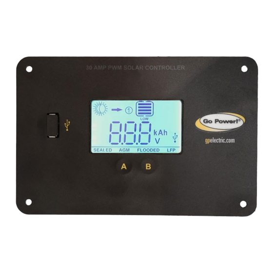
- Page 1 30AMP PWM SOLAR CONTROLLER User Manual GP-PWM-30-SB (SINGLE BANK - LITHIUM COMPATIBLE) © 2021 Go Power! Worldwide Technical Support and Product Information gpelectric.com Go Power! | Dometic 201-710 Redbrick Street Victoria, BC, V8T 5J3 Tel: 1.866.247.6527 Manual_GP-PWM-30-SB...
-
Page 3: Table Of Contents
CONTENTS 1. INSTALLATION OVERVIEW ........................1.1 INTRODUCTION ..........................4 1.2 SYSTEM VOLTAGE AND CURRENT ....................4 1.3 BATTERY TYPE ..........................4 1.4 LOW VOLTAGE DISCONNECT FUNCTION (USB PORT) ...............4 1.5 REGULATORY INFORMATION ......................4 1.6 SPECIFICATIONS ..........................4 2. WARNINGS ............................... 3. TOOLS AND MATERIALS NEEDED ...................... -
Page 4: Installation Overview
1. INSTALLATION OVERVIEW 1.1 INTRODUCTION A Solar Controller (or Charge Controller / Regulator) is an essential component of your photovoltaic solar system. The Controller maintains the life of the battery by protecting it from overcharging. When your battery has reached a 100% state of charge, the Controller prevents overcharging by limiting the current flowing into the batteries from your solar array. -
Page 5: Specifications
INSTALLATION OVERVIEW 1.6 SPECIFICATIONS DESCRIPTION VALUE Nominal System Voltage 12 VDC Dimensions (H x W x D): Range of Battery Input Voltage 9 – 15.5 VDC 149 x 98 x 32 mm Maximum Solar Continuous DC Charge Current Input 37.5 VDC 5.87 x 3.86 x 1.26 in Charging Output DC Voltage Range 9 –... -
Page 6: Warnings
2. WARNINGS Electricity can be very dangerous. Installation should be performed only Disconnect all power sources by a licensed electrician or qualified personnel. Observe all safety precautions of the battery manufacturer when handling Battery and wiring safety or working around batteries. When charging, batteries produce hydrogen gas, which is highly explosive. -
Page 7: Tools And Materials Needed
3. TOOL AND MATERIALS NEEDED • Flathead Screwdriver (for wire terminals) • Philips Screwdriver (for mounting screws) • Wire Cutter /Stripper If the GP-PWM-30-SB Controller was purchased with a Go Power! Solar Power Kit, then UV resistant wire is included. For Note instructions regarding the Go Power! Solar Power Kit installation, please refer to the Installation Guide provided with the Kit. -
Page 8: Wiring Diagram
6. WIRING DIAGRAMS IMPORTANT: All wiring must be in accordance to National Electrical Code, ANSI/NFPA 70. Always use appropriate circuit protection on any conductor attached to a battery. Connect the battery wiring to the controller first and then connect the battery wiring to the battery. Torque all terminal screws per the following: Stranded Copper 90°C Wire Wire Size AWG Rated Torque (in-lbs) With battery power attached, the controller should power up and display information. -
Page 9: Operating Instructions
7. OPERATING INSTRUCTIONS 7. OPERATING INSTRUCTIONS 7.1 SYSTEM VOLTAGE AND CURRENT When the GP-PWM-30-SB is connected to the battery, the controller will go into Power Up mode. Icons Displayed: All segments of the numerical display; backlight blinks. Depending on the battery voltage when the GP-PWM-30-SB Power Up occurs, the controller may do a Boost Charge or quickly go into Float Charge. The Charging Profile selected will commence the following day after a Power Up (refer to the Charging Profile Chart on page 11 for more details). -
Page 10: Battery Charging Profile Chart
OPERATING INSTRUCTIONS 7.3 BATTERY CHARGING PROFILE CHART BATTERY TYPE SEALED/GEL FLOODED Float Charge @ 25°C: 13.7V (+/- 0.1V) Bulk/Absorption Charge @ 25°C: 14.1V (+/- 0.1V) 14.4V (+/- 0.1V) 14.4V (+/- 0.1V) Set to 30 minutes every morning. Applied for 2 hours if the battery voltage drops below 12.3 volts. - Page 11 OPERATING INSTRUCTIONS 3 0 A M P P W M S O L A R C O N T R O L L E R Push the B Button to show the PV charging current. Icons Displayed: Ampere Symbol (A), Battery SOC 3 0 A M P P W M S O L A R C O N T R O L L E R Push the B Button to show the battery state of charge (shown as a percentage).
-
Page 12: Resetting The Ampere Hours Charged
3 0 A M P P W M S O L A R C O N T R O L L E R OPERATING INSTRUCTIONS 7.5 RESETTING THE AMPERE HOURS CHARGED 3 0 A M P P W M S O L A R C O N T R O L L E R To reset the count of ampere hours charged, toggle to the ampere hours charged. - Page 13 8. DISPLAY SYMBOLS SYMBOLS INDICATOR FOR Day Time: PV Charge Current Night Time Battery Voltage Battery State of Charge SEALED Sealed/Gel AGM/LFP FLOODED Flooded OTHER SYMBOLS USB charger ON (when charger is OFF, no symbol will show) Battery voltage is lower than 11.0V Whole display will start to blink Battery voltage >...
-
Page 14: Display Symbols
DISPLAY SYMBOLS BATTERY STATE OF CHARGE SYMBOLS BATTERY VOLTAGE Shows only after full Boost or Equalization Cycle >= 12.6V >= 11.8 -12.6V > 11.0 -11.8V <= 11.0V 100% Shows only after full Boost or Equalization Cycle >= 12.8V < 12.8V and > 11.0V <= 11.0V 9. -
Page 15: Frequently Asked Questions (Faqs)
10. FREQUENTLY ASKED QUESTIONS Before a problem is suspected with the system, read this section. There are numerous events that may appear as problems but are in fact perfectly normal. Please visit gpelectric.com for the most up-to-date FAQs. It seems like my flooded batteries are losing water over time. Flooded batteries may need to have distilled water added periodically to replace fluid loss during charging. Excessive water loss during a short period of time indicates the possibility of overcharging or aging batteries. -
Page 16: Troubleshooting Problems
11. TROUBLESHOOTING PROBLEMS How to Read this Section Troubleshooting Problems is split into three sub-sections, grouped by symptoms involving key components. Components considered irrelevant in a diagnosis are denoted ‘Not Applicable’ (N/A). A multimeter or voltmeter may be required for some procedures listed. It is imperative all electrical precautions stated in the Warning Section and outlined in the Installation Section are followed. -
Page 17: Problems With Current
TROUBLESHOOTING PROBLEMS 11.3 PROBLEMS WITH CURRENT Current Reading: 0 A Time of Day: Daytime, clear sunny skies Possible Cause: Current is being limited below 1 Amp as per normal operation or poor connection between solar array and controller. How to tell: The State of Charge (SOC) screen is close to 100% and the Sun and Battery icon are present with an arrow between. - Page 18 TROUBLESHOOTING PROBLEMS 11.4 CONTROLLER FLASHING Possible Cause: This behavior is usually the controller dealing with a very high C or voltage rate (Above 15.5 volts). Even though the controller can handle up to 30A, if the battery capacity is too small for the panel input current. The voltage shoots up too high, too quickly, tripping the high voltage flashing. Solution increase battery capacity.
-
Page 19: Limited Warranty
12. LIMITED WARRANTY Go Power! warrants the GP-PWM-10 for a period of five (5) years from the date of shipment from its factory. This warranty is valid against defects in materials and workmanship for the five(5) year warranty period. It is not valid against defects resulting from, but not limited to: • Misuse and/or abuse, neglect or accident • Exceeding the unit’s design limits • Improper installation, including, but not limited to, improper environmental protection and improper hook-up • Acts of God, including lightning, floods, earthquakes, fire, and high winds • Damage in handling, including damage encountered during shipment This warranty shall be considered void if the warranted product is in any way opened or altered. - Page 20 © 2021 Go Power! Worldwide Technical Support and Product Information gpelectric.com Go Power! | Dometic 201-710 Redbrick Street Victoria, BC, V8T 5J3 Tel: 1.866.247.6527 Manual_GP-PWM-30-SB...
Need help?
Do you have a question about the Go Power! GP-PWM-30-SB and is the answer not in the manual?
Questions and answers