
Related Manuals for SAMES KREMLIN Inorecip V


Summary of Contents for SAMES KREMLIN Inorecip V
- Page 1 User manual Inorecip V Inomotion SAMES KREMLIN SAS - 13, Chemin de Malacher - 38240 MEYLAN - FRANCE Tel. 33 (0)4 76 41 60 60 - www.sames-kremlin.com Index revision : A 7140...
- Page 2 SAMES KREMLIN SAS operating manuals are written in French and translated into English, German, Spanish, Italian and Portuguese. The French version is deemed the official text and SAMES KREMLIN will not be liable for the translations into other languages. Index revision : A...
-
Page 3: Table Of Contents
2. Introduction - - - - - - - - - - - - - - - - - - - - - - - - - - - - - - - - - - - - - - - - 11 2.1. General - Inorecip V ....... 11 2.2. - Page 4 9.1. Inorecip V ........
-
Page 5: Inorecip V
Inorecip H. see RT Nr 7167 1.1. Marking Inorecip H is classified as category 3 according to the ATEX 2014/34/EU directive. INORECIP V INORECIP V II 3 D Ex h IIIC T135° C Dc 0° C ≤ ≤ Tamb Tamb ≤... -
Page 6: Simplified Analysis Of Potential Ignition Sources According
This document contains information that all operators should be aware of and understand before using the Inorecip V and Inomotion. This information highlights situations that could result in serious damage and indicates the precautions that should be taken to avoid them. - Page 7 5 The ambient operating temperature must be between 0° and 40° C. 6 The Inorecip V and Inomotion equipment must be maintained regularly in accordance with the indications and instructions given by SAMES KREMLIN.
-
Page 8: Important Recommendations
1.5. Important recommendations 1.5.1. Installation of the Inorecip V reciprocator The Inorecip V alone or mounted on an Inorecip H must be installed on a flat floor with a resis- tance of 40 daN/cm2. It is better to equalize the loads on both sides of the assembly. If this is not possible, the admis- sible overhang must not be more than 30 cm from the robot axis. -
Page 9: Ambient Temperature
WARNING : it is important, in order to avoid any material breaking, to adjust the mechanical stops of the carriage with the mounted projectors, before starting up the Inomotion (see § 4.5 page 24). 1.5.5. Ambient temperature Inorerecip V and Inomotion are designed to normally operate at an ambient temperature comprised between 0°C and + 40°C. -
Page 10: Guarantee
• the customer's negligence or inattention, • incorrect use, • use of a control system not designed by SAMES KREMLIN or a SAMES KREMLIN con- trol system modified by a third party without written permission from an authorized SAMES KREMLIN technical agent, •... -
Page 11: Introduction
The Inomotion control module allows to remotely control the vertical reciprocating mechanism of the Inorecip V and the horizontal positioning of the Inorecip H (option). It is connected by power and control cables to the box located at the rear of the Inorecip V. 2.3. Inorecip H (option) The In and Out carriage Inorecip H is an unit placed under the Inorecip V reciprocator giving it the possibility to move along a second horizontal axis. -
Page 12: Description
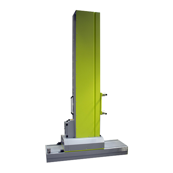
2.4. Description 2.4.1. Inorecip V Free toothed pulley Lifting rings Belt tension adjustment Upper stop Antistatic toothed belt Support cables and powder hoses for projectors Counte- rweight Lower stop Handle Position sen- Electrical box Carriage equip- ped with pro- Back Wheels... -
Page 13: Inomotion
Manufacturer marking Manufacturer's certification label PLC connection PLC connection SYSTEM I/O connection Connection of inputs/outputs TCP/IP connection TCP/IP connection SYSTEM POWER connection Power supply of the Inorecip V Power switch on Main and emergency stop switch Index revision : A 7140... -
Page 14: Characteristics
3. Characteristics 3.1. Dimensions (mm) of the Inorecip V 1233 1233 Ø50 50 1785 1785 1870 1870 3.2. General characteristics of the Inorecip V Inorecip V Height (mm) 2524 2824 3124 3424 3724 4024 Stroke (mm) 1200 1500 1800 2100... -
Page 15: Dimensions (Mm) Of The Inorecip V And Inorecip H
3.3. Dimensions (mm) of the Inorecip V and Inorecip H assembly 80 80 1900 1900 The characteristics of the Inorecip H are described in the user manual (see RT Nr 7167). 3.4. General characteristics of the Inomotion Inomotion Height 182 mm... -
Page 16: Starting Up
28). When starting up the Inomotion, each axis will automatically position itself on its reference point, at the low electrical stop for the Inorecip V, and at the front for the Inorecip H 4.1. Tools The tools listed below are recommended for installation and maintenance of the equipment. -
Page 17: Installation Of The Inorecip H (Option)
Remove the two protective covers of the Protective covers Inorecip H with 4 M4 screws per cover. Remove the 2 side covers of Inorecip V with 6 M4 Side covers screws per cover. Remove the 4 wheels of the Inorecip V by remo- ving the 4 M8 screws per wheel. - Page 18 Electrical Cables Fix the cable carrier chain support on the Inorecip V with 4 screws and fix the cable carrier chain on its support with 2 screws. Install the drive and the electronic board delivered with the 2nd axis box transformation cable kit (P/N # 130002077).
-
Page 19: Electrical Connection Inorecip V - Inomotion Control Unit
4.2.3. Electrical connection Inorecip V - Inomotion control unit From the Inomotion control module, connect the electrical cables to the plugs of the electrical box at the back of the Inorecip V. Note: the electrical equipment will be more than one meter away from the opening area of the cabin (outside explosive atmosphere). -
Page 20: Grounding Connection
Inorecip V - 2 Inomotion 4.2.4. Grounding connection WARNING : it is imperative to connect the Inorecip V to the ground of the control unit or to a good quality ground. From the control unit or a good quality ground,... -
Page 21: Electrical Diagram Of The Inorecip V
4.2.5. Electrical diagram of the Inorecip V Index revision : A 7140... -
Page 22: Electrical Diagram Of The Inomotion
4.2.6. Electrical diagram of the Inomotion LINE FILTER LINE FILTER ELON05003 ELON05003 Index revision : A 7140... -
Page 23: Reference Point Of Inorecip V
Inomotion, each axis will position itself, at a slow speed, on its reference point automatically. At the bottom, on the position sensor for the Inorecip V and at the front for the Inorecip H. The mechanical rubber stops are positioned about 50 mm downstream of their respective position sensor. -
Page 24: Adjustment Of The Stops
4.5. Adjustment of the stops The stops limit the stroke of the altitude carriage Adjustment procedure for the two stops: • Step 1: Remove the side panel. • Step 2: Move down the height carriage until the lowest projector is about 50 mm above the lower edge of the slot of the powder booth •... -
Page 25: Counterweight Adjustment
This balance is achieved by adding or removing weights that are accessible after removing the side panels of the Inorecip V. Each ballast weighs approximately 1.8 kg. Tighten the 4 fixing nuts (M8) by counterweights after changing the ballast. -
Page 26: Operating Of The Inomotion
5. Operating of the Inomotion 5.1. Screen Operating Modes The Inomotion control module allows the display and setting of the operating parameters of the Inorecip V and Inorecip H. This screen is used to enter the operating instructions for the operating modes: Item... -
Page 27: Start And Setup Menu
5.2. Start and setup menu Power is turned on by the switch on the back of the Inomotion and by pressing the on/off but- ton on the front panel to activate the display. The main menu appears, and the operator can then begin to set up the module (see §... -
Page 28: Axis Configuration
Serial communication: The Inomotion has an RJ45 connection that allows the module to be connected to a PLC. In this case, the setting parameters of the module are processed directly via the PLC and the Inomotion module is used as a "Slave". Info code Settings Factory preset... -
Page 29: Main Menu Page
5.4. Main menu page Each parameter can be selected with the keys (5,6,7,8,9) on the right-hand side and change their values with the rotating button (10). 1500 1st line: Setting of the upper inversion point. The maximum value is set on the configuration page. 2nd line: setting of the lower inversion point. -
Page 30: Start-Up Procedure
5.6. Start-up procedure • Step 1: After entering and saving a program, select the required axis(es) with the key (13) and activate or deactivate the axis number with the key (12). The axis number turns green when active. • Step 2: Select the required program number for each axis using the rotating button (10). •... - Page 31 Error code Symptoms Remedies - Check sensor connections and whether it is defective Start position error - Check if the belt is broken or too loose - Check the stroke parameters from the programs via the interface. The distance between the upper and Short stroke error lower stroke limits is too short in rela- tion to the set speed.
-
Page 32: Maintenance
6. Maintenance WARNING : Before any intervention on the Inorecip V, it is imperative to cut off the power sup- ply. 6.1. Maintenance summary table Therefore, the frequency of maintenance indicated in the procedures below is only indicative. The user will have to create his own maintenance range as he uses the SAMES KREMLIN equipment. -
Page 33: Replacement
WARNING : Before removing the belt, it is necessary to secure the counterweight To do so, the projectors mounted on the Inorecip V have been removed from the booth: Move the altitude carriage down to altitude until it touches the lower stop. -
Page 34: Procedure C2: Replacement Of The Coder
6.3.2. Procedure C2: Replacement of the coder After 3 to 5,000 hours of operation, or in case of accidental damage, it may be necessary to change the coder. Caution: The coder is very fragile, especially its connection terminals. For proper operation of the equipment, it is recommended that the antistatic toothed belt on the carriage is correctly adjusted. -
Page 35: Procedure C3: Replacement Of The Rollers Of The Altitude
Adjust the rollers(see § 4.2 page • Proceed in the reverse order to reassemble the plates and panels described above. • Check the belt tension(see § 4.8 page before reassembling the Inorecip V side panels. Index revision : A 7140... -
Page 36: Procedure C4: Replacement Of The Rollers Of The Counterweight Carriage
• Remove the side panels. • Secure the counterweight carriage by placing a cleat (100x100) of a size adapted to the height between the counterweight carriage and the base of the Inorecip V. • Remove the antistatic toothed belt (see § 6.3.1 page 33). -
Page 37: Drive Settings
6.4. Drive settings For Inorecip V to work properly, check the settings indicated in the table below on the drive located in the electrical box of the reciprocator. Adjustment procedure of the drive: • Step 1: Press key (D). "1-" is displayed on the screen. -
Page 38: Settings Of The Electronic Board
Set the axis maps according to the order of the axes to be used. The Inomotion control unit can control up to 8 axes. WARNING : The electronic control boards are set up by SAMES KREMLIN. Do not modify these parameters unless necessary. -
Page 39: Manutention
7. Manutention WARNING : Inorecip V must be handled with care by at least 2 operators who must never be under the reciprocator during handling. 7.1. Packing, transport Special precautions must be taken when transporting Inorecip V when: • The customer must package, transport and ship the product himself, so that SAMES KREMLIN can carry out repair or maintenance work •... - Page 40 1500 Stroke length 1800 Stroke length 2100 Stroke length Index revision : A 7140...
-
Page 41: Package Weight
2400 Stroke length 2700 Stroke length 7.1.2. Package weight Stroke (mm) Inorecip V (kg) Packed (kg) 2 Inorecip V packed 1200 277.5 1500 1800 322.5 2100 2400 382.5 1050 2700 1130 Inorecip H Approx. 250 kg with one pallet Inorecip H... -
Page 42: Troobleshootings
Symptoms Probable Causes Remedies The belt is slack and causes a loss of Tighten the belt The Inorecip V works, carriage position but there is a clicking The nuts of the belt fastening on the noise when the Tighten these nuts... -
Page 43: Spare Parts List
9. Spare parts list 9.1. Inorecip V Mainte- Unit nance level Item Part Number Description sale spare parts 130002072-180AT Inorecip V 130002088 Free Toothed Pulley Kit 130002087 Antistatic toothed belt 130002086 Altitude carriage roller kit 110002897AT Position sensor 130002109 Spacer... -
Page 44: Inomotion
9.2. Inomotion Mainte- nance level Unit of Item Part Number Description sale spare parts 130002073 Inomotion 130002076 Power and control cable kit Level 1: Standard preventive maintenance Level 2: Corrective maintenance Level 3: Exceptional maintenance Index revision : A 7140... -
Page 45: Motorization Assembly
9.3. Motorization assembly Mainte- nance level Unit of Item Part Number Description sale spare parts 110002895AT Geared motor 0.37 kW 110002896AT Coder Level 1: Standard preventive maintenance Level 2: Corrective maintenance Level 3: Exceptional maintenance Index revision : A 7140... -
Page 46: Additional Equipments
9.4. Additional equipments Mainte- nance level Unit of Item Part Number Description sale spare parts 200000412 Fixing nut 50/40 900001079 Aluminum tube D: 50 x 5 x 2200 mm Mainte- nance level Unit of Item Part Number Description sale spare parts 749805 Fixing nut 50/30 Level 1: Standard preventive maintenance... -
Page 47: Revision Index History
10. Revision index History Rev. Date Description Modification locating Nov. 2020 First issue Index revision : A 7140...
Need help?
Do you have a question about the Inorecip V and is the answer not in the manual?
Questions and answers